TPS54325-Q1
SLVSAT1A – JUNE 2011 – REVISED JULY 2022
TPS54325-Q1 4.5-V to 18-V, 3-A Output Synchronous SWIFT Step-Down Switcher
With Integrated FET
1 Features
2 Applications
•
•
•
•
•
•
•
•
•
•
•
•
•
•
•
•
Qualified for automotive applications
D-CAP2™ mode enables fast transient response
Low output ripple and allows ceramic output
capacitor
4.5-V to 18-V wide VCC input voltage range
2.0-V to 18-V wide VIN input voltage range
0.76-V to 5.5-V output voltage range
Highly efficient integrated FETs optimized
for lower duty cycle applications
–120 mΩ (high side) and 70 mΩ (low side)
High efficiency, less than 10 μA at shutdown
High initial bandgap reference accuracy
Adjustable soft start
Prebiased soft start
700-kHz switching frequency (fSW)
Cycle-by-cycle overcurrent limit
Power-good output
Create a custom design using the TPS54325-Q1
with the WEBENCH® Power Designer
Wide range of applications for low voltage system
– Digital TV power supply
– High definition Blue-ray Disc™ players
– Networking home terminal
– Digital set top box (STB)
3 Description
The TPS54325-Q1 is an adaptive on-time D-CAP2
mode synchronous buck converter. The TPS54325Q1 enables system designers to complete the suite
of power bus regulators for various end equipments
with a cost effective, low component count, low
standby current solution. The main control loop for
the TPS54325-Q1 uses the D-CAP2 mode control,
which provides a very fast transient response with no
external components. The TPS54325-Q1 also has a
proprietary circuit that enables the device to adapt to
both low equivalent series resistance (ESR) output
capacitors, such as POSCAP or SP-CAP, and ultralow ESR ceramic capacitors. The device operates
from a 4.5-V to 18-V VCC input, and from a 2.0-V
to 18-V VIN input power supply voltage. The output
voltage can be programmed between 0.76 V and 5.5
V. The device also features an adjustable slow-start
time and a power good function. The TPS54325-Q1
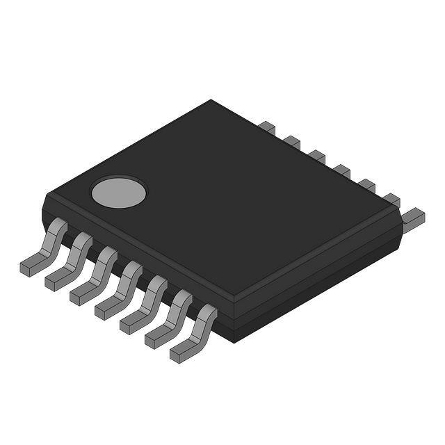
is available in the 14-pin HTSSOP package, and
designed to operate from –40°C to 105°C.
Device Information
Part Number
Package
Body Size (NOM)
TPS54325-Q1
HTSSOP
5.00 mm × 4.40 mm
TPS54325TPWPRQ1
VOUT (50 mV / div)
IOUT (2 A / div)
Simplified Schematic
100 µs / div
Load Transient Response
An IMPORTANT NOTICE at the end of this data sheet addresses availability, warranty, changes, use in safety-critical applications,
intellectual property matters and other important disclaimers. PRODUCTION DATA.
�TPS54325-Q1
www.ti.com
SLVSAT1A – JUNE 2011 – REVISED JULY 2022
Table of Contents
1 Features............................................................................1
2 Applications..................................................................... 1
3 Description.......................................................................1
4 Revision History.............................................................. 2
5 Pin Configuration and Functions...................................3
6 Specifications.................................................................. 4
6.1 Absolute Maximum Ratings........................................ 4
6.2 ESD Ratings............................................................... 4
6.3 Recommended Operating Conditions.........................4
6.4 Thermal Information....................................................5
6.5 Electrical Characteristics.............................................5
6.6 Typical Characteristics................................................ 7
7 Detailed Description........................................................8
7.1 Overview..................................................................... 8
7.2 Functional Block Diagram........................................... 8
7.3 Feature Description.....................................................8
7.4 Device Functional Modes............................................9
8 Application and Implementation.................................. 11
8.1 Application Information..............................................11
8.2 Typical Application.................................................... 11
9 Power Supply Recommendations................................15
10 Layout...........................................................................16
10.1 Layout Guidelines................................................... 16
10.2 Layout Example...................................................... 16
10.3 Thermal Information................................................16
11 Device and Documentation Support..........................18
11.1 Device Support........................................................18
11.2 Documentation Support.......................................... 18
11.3 Receiving Notification of Documentation Updates.. 18
11.4 Support Resources................................................. 18
11.5 Trademarks............................................................. 18
11.6 Electrostatic Discharge Caution.............................. 18
11.7 Glossary.................................................................. 19
12 Mechanical, Packaging, and Orderable
Information.................................................................... 19
4 Revision History
NOTE: Page numbers for previous revisions may differ from page numbers in the current version.
Changes from Revision * (June 2011) to Revision A (July 2022)
Page
• Updated the numbering format for tables, figures, and cross-references throughout the document..................1
• Added ESD Ratings, Pin Configuration and Functions, Detailed Description, Functional Block Diagram,
Feature Description, Device Functional Modes, Application and Implementation, Application Information,
Typical Application, Design Requirements, Detailed Design Procedure, Application Curves, Power Supply
Recommendations, Layout, Layout Guidelines, Layout Example, Device and Documentation Support, and
Mechanical, Packaging, and Orderable Information ..........................................................................................1
• Corrected thermal information............................................................................................................................ 5
2
Submit Document Feedback
Copyright © 2022 Texas Instruments Incorporated
Product Folder Links: TPS54325-Q1
�TPS54325-Q1
www.ti.com
SLVSAT1A – JUNE 2011 – REVISED JULY 2022
5 Pin Configuration and Functions
1
14
VCC
VFB
2
13
VIN
VREG5
3
12
VBST
11
SW2
SW1
VO
POWERPAD
TPS54325
SS
4
GND
5
10
PG
6
9
PGND2
EN
7
8
PGND1
PWP
HTSSOP14
Figure 5-1. 14-Pin PWP HTSSOP Pinout
Table 5-1. Pin Functions
Pin
Name
NO.
Description
VO
1
Connect this pin to the output of the converter. This pin is used for on-time adjustment.
VFB
2
Converter feedback input. Connect this pin with a feedback resistor divider.
VREG5
3
5.5-V power supply output. Connect a capacitor (typically 1μF) to GND.
SS
4
Soft-start control. Connect an external capacitor to GND.
GND
5
Signal ground pin
PG
6
Open-drain power-good output
EN
7
Enable control input
PGND1, PGND2
SW1, SW2
8, 9
Ground returns for low-side MOSFET. These ground returns also serve as inputs of current comparators.
Connect PGND and GND strongly together near the IC.
10, 11
Switch node connections between the high-side NFET and low-side NFET. These connections also serve
as inputs to current comparators.
VBST
12
Supply input for high-side NFET gate driver (boost terminal). Connect a capacitor from this pin to
respective SW1 and SW2 terminals. An internal PN diode is connected between VREG5 to VBST pin.
VIN
13
Power input and connected to high-side NFET drain
14
Supply input for the 5-V internal linear regulator for the control circuitry
VCC
PowerPAD
Back side Thermal pad of the package. Must be soldered to achieve appropriate dissipation. Connect to GND.
Submit Document Feedback
Copyright © 2022 Texas Instruments Incorporated
Product Folder Links: TPS54325-Q1
3
�TPS54325-Q1
www.ti.com
SLVSAT1A – JUNE 2011 – REVISED JULY 2022
6 Specifications
6.1 Absolute Maximum Ratings
over operating free-air temperature range (unless otherwise noted)(1)
VI
Input voltage range
MIN
MAX
VIN, VCC, EN
–0.3
20
VBST
–0.3
26
VBST (vs SW1, SW2)
–0.3
6.5
VFB, VO, SS, PG
–0.3
6.5
–2
20
SW1, SW2
SW1, SW2 (10-ns transient)
–3
20
VREG5
–0.3
6.5
PGND1, PGND2
–0.3
0.3
UNIT
V
VO
Output voltage range
Vdiff
Voltage from GND to POWERPAD
–0.2
0.2
V
TJ
Operating junction temperature
–40
150
°C
Tstg
Storage temperature
–55
150
°C
(1)
V
Stresses beyond those listed under the absolute maximum ratings may cause permanent damage to the device. These are stress
ratings only, and functional operation of the device at these or any other conditions beyond those indicated under the recommended
operating conditions is not implied. Exposure to absolute maximum rated condition for extended periods may affect device reliability.
6.2 ESD Ratings
VALUE
V (ESD)
(1)
(2)
Electrostatic
discharge
Human-body model (HBM), per ANSI/ESDA/JEDEC
JS-001(1)
UNIT
±2000
Charged device model (CDM), per JEDEC specification JESD22-C101, all pins(2)
V
±1000
JEDEC document JEP155 states that 500-V HBM allows safe manufacturing with a standard ESD control process.
JEDEC document JEP157 states that 250-V CDM allows safe manufacturing with a standard ESD control process.
6.3 Recommended Operating Conditions
over operating free-air temperature range, VCC, VIN = 12 V (unless otherwise noted)
VCC
Supply input voltage range
VIN
Power input voltage range
VI
Input voltage range
MAX
4.5
18
V
V
2
18
VBST
–0.1
24
VBST, (vs SW1, SW2)
–0.1
6
SS, PG
–0.1
6
EN
–0.1
18
VO, VFB
–0.1
5.5
SW1, SW2
–1.8
18
–3
18
SW1, SW2 (10-ns transient)
4
MIN
UNIT
V
PGND1, PGND2
–0.1
0.1
VO
Output voltage range
VREG5
–0.1
6
V
IO
Output current range
IVREG5
0
10
mA
TA
Operating free-air temperature
–40
105
°C
TJ
Operating junction temperature
–40
125
°C
Submit Document Feedback
Copyright © 2022 Texas Instruments Incorporated
Product Folder Links: TPS54325-Q1
�TPS54325-Q1
www.ti.com
SLVSAT1A – JUNE 2011 – REVISED JULY 2022
6.4 Thermal Information
PWP
THERMAL METRIC(1)
(1)
UNIT
14 PINS
R θJA
Junction-to-ambient thermal resistance
46.3
°C/W
R θJC(top)
Junction-to-case (top) thermal resistance
36.6
°C/W
R θJB
Junction-to-board thermal resistance
31.4
°C/W
ψ JT
Junction-to-top characterization parameter
1.7
°C/W
ψ JB
Junction-to-board characterization parameter
31.1
°C/W
R θJC(bot)
Junction-to-case (bottom) thermal resistance
7.2
°C/W
For more information about traditional and new thermal metrics, see the Semiconductor and IC package thermal metrics application
report.
6.5 Electrical Characteristics
over operating free-air temperature range (unless otherwise noted)
PARAMETER
TEST CONDITIONS
MIN
TYP
MAX
UNIT
850
1300
μA
10
μA
SUPPLY CURRENT
IVCC
Operating – nonswitching supply
current
VCC current, TA = 25°C, EN = 5 V,
VFB = 0.8 V
ICCSDN
Shutdown supply current
VCC current, TA = 25°C, EN = 0 V
LOGIC THRESHOLD
VENH
EN high-level input voltage
EN
VENL
EN low-level input voltage
EN
2
V
0.4
V
VFB VOLTAGE AND DISCHARGE RESISTANCE
TA = 25°C, VO = 1.05 V
757
TA = 0°C to 105°C, VO = 1.05 V
753
TA = –40°C to 105°C, VO = 1.05 V
750
VFBTH
VFB threshold voltage
IVFB
VFB input current
VFB = 0.8 V, TA = 25°C
RDischg
VO discharge resistance
EN = 0 V, VO = 0.5 V, TA = 25°C
765
775
777
mV
780
0
±0.1
μA
50
100
Ω
5.5
5.7
V
20
mV
100
mV
VREG5 OUTPUT
VVREG5
VREG5 output voltage
TA = 25°C, 6.0 V < VCC < 18 V, 0 <
IVREG5 < 5 mA
VLN5
Line regulation
6.0 V < VCC < 18 V, IVREG5 = 5 mA
VLD5
Load regulation
0 mA < IVREG5 < 5 mA
IREG5
Output current
VCC = 6 V, VREG5 = 4.0 V, TA = 25°C
Rdsonh
High-side switch resistance
25°C, VBST – SW1, SW2 = 5.5 V
Rdsonl
Low-side switch resistance
25°C
5.3
70
mA
120
mΩ
70
mΩ
MOSFET
CURRENT LIMIT
Iocl
Current limit
TA = 25°C to 105°C
TA = –40°C
3.5
4.1
3.25
3.5
A
THERMAL SHUTDOWN
tSDN
Thermal shutdown threshold
Shutdown temperature
Hysteresis
150
25
°C
ON-TIME TIMER CONTROL
tON
On time
VIN = 12 V, VO = 1.05 V
145
ns
tOFF(MIN)
Minimum off time
TA = 25°C, VFB = 0.7 V
260
ns
SOFT START
Submit Document Feedback
Copyright © 2022 Texas Instruments Incorporated
Product Folder Links: TPS54325-Q1
5
�TPS54325-Q1
www.ti.com
SLVSAT1A – JUNE 2011 – REVISED JULY 2022
6.5 Electrical Characteristics (continued)
over operating free-air temperature range (unless otherwise noted)
MIN
TYP
MAX
ISSC
SS charge current
PARAMETER
VSS = 0 V
TEST CONDITIONS
1.4
2.0
2.6
ISSD
SS discharge current
VSS = 0.5 V
0.1
0.2
85%
90%
UNIT
μA
mA
POWER GOOD
VTHPG
PG threshold
IPG
PG sink current
VFB rising (good)
VFB falling (fault)
PG = 0.5 V
95%
85%
2.5
5
115%
120%
mA
OUTPUT UNDERVOLTAGE AND OVERVOLTAGE PROTECTION
VOVP
Output OVP trip threshold
TOVPDEL
Output OVP prop delay
VUVP
Output UVP trip threshold
tUVPDEL
Output UVP delay
tUVPEN
Output OVP enable delay
OVP detect
125%
5
UVP detect
65%
70%
Hysteresis
10%
Relative to soft-start time
× 1.7
μs
75%
0.25
ms
UVLO
VUVLO
6
UVLO threshold
Wake-up VREG5 voltage
3.45
3.70
3.95
Hysteresis VREG5 voltage
0.15
0.25
0.35
Submit Document Feedback
V
Copyright © 2022 Texas Instruments Incorporated
Product Folder Links: TPS54325-Q1
�TPS54325-Q1
www.ti.com
SLVSAT1A – JUNE 2011 – REVISED JULY 2022
6.6 Typical Characteristics
1200
8
IVCCSDN - Shutdown Current - µA
IVCC - Supply Current - µA
1000
800
600
400
200
0
-50
0
50
100
6
4
2
0
-50
150
0
TJ - Junction Temperature - °C
100
150
Figure 6-2. VCC Shutdown Current vs Junction Temperature
Figure 6-1. VCC Temperature vs Junction Temperature
900
fSW - Switching Frequency - kHz
900
fSW - Switching Frequency - kHz
50
TJ - Junction Temperature - °C
800
VO = 1.8 V
700
600
VO = 3.3 V
500
0
5
10
15
800
VO = 1.8 V
700
VO = 2.5 V
600
20
VIN - Input Voltage - V
500
0.0
Figure 6-3. Switching Frequency vs Input Voltage (IO = 1 A)
0.5
1.0
1.5
2.0
2.5
3.0
IO - Output Current - A
Figure 6-4. Switching Frequency vs Output Current
Submit Document Feedback
Copyright © 2022 Texas Instruments Incorporated
Product Folder Links: TPS54325-Q1
7
�TPS54325-Q1
www.ti.com
SLVSAT1A – JUNE 2011 – REVISED JULY 2022
7 Detailed Description
7.1 Overview
The TPS54325-Q1 is a 3-A synchronous step-down (buck) converter with two integrated N-channel MOSFETs.
The device operates using D-CAP2 mode control. The fast transient response of D-CAP2 control reduces the
output capacitance required to meet a specific level of performance. Proprietary internal circuitry allows the use
of low-ESR output capacitors including ceramic and special polymer types.
7.2 Functional Block Diagram
-30%
UV
14
VO
VIN
VIN
OV
1
VCC
13
+20%
VREG5
Control logic
12
VBST
Ref
SS
1 shot
SW
VFB
SGND
10
XCON
VREG5
VREG5
Ceramic
Capacitor
3
SS
1uF
VO
11
2
9
4
8
PGND
Softstart
PGND
SW
SS
5
PGND
SGND
PG
OCP
GND
Ref
VCC
6
-10%
UV
VREG5
EN
7
OV
UVLO
EN
Logic
UVLO
Protection
Logic
TSD
REF
Ref
7.3 Feature Description
7.3.1 Soft Start and Pre-Biased Soft Start
The TPS54325-Q1 has an adjustable soft start. When the EN pin becomes high, 2.0-μA current begins charging
the capacitor, which is connected from the SS pin to GND. Smooth control of the output voltage is maintained
during start-up. Use the following equation to find the slow-start time. VFB voltage is 0.765 V and SS pin source
current is 2 μA.
TSS ms =
8
C6 nF × VREF
C6 nF × 0.765
=
2
ISS μA
Submit Document Feedback
(1)
Copyright © 2022 Texas Instruments Incorporated
Product Folder Links: TPS54325-Q1
�TPS54325-Q1
www.ti.com
SLVSAT1A – JUNE 2011 – REVISED JULY 2022
The TPS54325-Q1 contains a unique circuit to prevent current from being pulled from the output during start-up
in the condition the output is prebiased. When the soft start commands a voltage higher than the prebias level
(internal soft start becomes greater than feedback voltage (VFB)), the controller slowly activates synchronous
rectification by starting the first low-side FET gate driver pulses with a narrow on time. The device then
increments that on time on a cycle-by-cycle basis until it coincides with the time dictated by (1 – D), where
D is the duty cycle of the converter. This scheme prevents the initial sinking of the prebias output, and ensures
that the out voltage (VO) starts and ramps up smoothly into regulation and the control loop is given time to
transition from prebiased start-up to normal mode operation.
7.3.2 Power Good
The TPS54325-Q1 has a power-good output. The power-good function is activated after soft start has finished.
If the output voltage becomes within –10% of the target value, internal comparators detect a power-good state
and the power-good signal becomes high. During start-up, power good start after 1.7 times the soft-start time to
avoid a glitch of power-good signal. If the feedback voltage goes under 15% of the target value, the power-good
signal becomes low after a 10-μs internal delay.
7.3.3 Output Discharge Control
The TPS54325-Q1 discharges the output when EN is low or the controller is turned off by the protection
functions (OVP, UVP, UVLO, and thermal shutdown). The device discharges outputs using an internal 50-Ω
M,OSFET which is connected to VO and PGND. The internal low-side MOSFET is not turned on during the
output discharge operation to avoid the possibility of causing negative voltage at the output.
7.3.4 Current Protection
The TPS54325-Q1 has cycle-by-cycle overcurrent limiting control. The inductor current is monitored during
the off state and the controller keeps the off state when the inductor current is larger than the overcurrent
trip level. In order to provide both good accuracy and cost effective solution, the device supports temperature
compensated internal MOSFET RDS(on) sensing.
The inductor current is monitored by the voltage between PGND pin and SW1 and SW2 pins. In an overcurrent
condition, the current to the load exceeds the current to the output capacitor, thus the output voltage tends to fall
off. Eventually, the output voltage ends up crossing the undervoltage protection threshold and shutdown.
7.3.5 Overvoltage and Undervoltage Protection
The TPS54325-Q1 monitors a resistor divided feedback voltage to detect overvoltage and undervoltage. When
the feedback voltage becomes higher than 120% of the target voltage, the OVP comparator output goes high
and the circuit latches the high-side MOSFET driver turns off and the low-side MOSFET turns on.
When the feedback voltage becomes lower than 70% of the target voltage, the UVP comparator output goes
high and an internal UVP delay counter begins. After 250 μs, the device latches off both internal top and bottom
MOSFET. This function is enabled approximately 1.7 × soft-start time.
7.3.6 UVLO Protection
The TPS54325-Q1 has undervoltage lockout protection (UVLO) that monitors the voltage of VREG5 pin. When
the VREG5 voltage is lower than UVLO threshold voltage, the TPS54325-Q1 is shut off. This is non-latch
protection.
7.3.7 Thermal Shutdown
The TPS54325-Q1 monitors the temperature of itself. If the temperature exceeds the threshold value (typically
150°C), the device is shut off. This is non-latch protection.
7.4 Device Functional Modes
7.4.1 PWM Operation
The main control loop of the TPS54325-Q1 is an adaptive on-time pulse width modulation (PWM) controller that
supports a proprietary D-CAP2 mode control. D-CAP2 mode control combines constant on-time control with an
Submit Document Feedback
Copyright © 2022 Texas Instruments Incorporated
Product Folder Links: TPS54325-Q1
9
�TPS54325-Q1
www.ti.com
SLVSAT1A – JUNE 2011 – REVISED JULY 2022
internal compensation circuit for pseudo-fixed frequency and low external component count configuration with
both low-ESR and ceramic output capacitors. This mode is stable even with virtually no ripple at the output.
At the beginning of each cycle, the high-side MOSFET is turned on. This MOSFET is turned off after internal the
one shot timer expires. This one shot timer is set by the converter input voltage ,VIN, and the output voltage, VO,
to maintain a pseudo-fixed frequency over the input voltage range, hence it is called adaptive on-time control.
The one-shot timer is reset and the high-side MOSFET is turned on again when the feedback voltage falls below
the reference voltage. An internal ramp is added to the reference voltage to simulate output ripple, eliminating
the need for ESR-induced output ripple from D-CAP2 mode control.
7.4.2 PWM Frequency and Adaptive On-Time Control
The TPS54325-Q1 uses an adaptive on-time control scheme and does not have a dedicated on-board oscillator.
The TPS54325-Q1 runs with a pseudo-constant frequency of 700 kHz by using the input voltage and output
voltage to set the on-time one-shot timer. The on time is inversely proportional to the input voltage and
proportional to the output voltage, therefore, when the duty ratio is VOUT / VIN, the frequency is constant
10
Submit Document Feedback
Copyright © 2022 Texas Instruments Incorporated
Product Folder Links: TPS54325-Q1
�TPS54325-Q1
www.ti.com
SLVSAT1A – JUNE 2011 – REVISED JULY 2022
8 Application and Implementation
Note
Information in the following applications sections is not part of the TI component specification,
and TI does not warrant its accuracy or completeness. TI’s customers are responsible for
determining suitability of components for their purposes, as well as validating and testing their design
implementation to confirm system functionality.
8.1 Application Information
The TPS54325-Q1 device is typically used as a step-down converter, which converts a voltage in the range of
4.5 V to 18 V to a lower voltage. WEBENCH software is available to aid in the design and analysis of circuits
8.2 Typical Application
TPS54325TPWPRQ1
Figure 8-1. Schematic Diagram for Design Example
8.2.1 Design Requirements
Table 8-1. Design Parameters
Parameter
Conditions
Input voltage
MIN
TYP
MAX
Unit
5
Output voltage
V
1.05
Operating frequency
VI = 12 V, IO = 1 A
Output current
V
700
0
kHz
3
Output ripple voltage
VI = 12 V, IO = 3 A
9
Efficiency
VI = 12 V, VOUT = 3.3 V, IOUT = 1.2 A
91%
A
mVpp
8.2.2 Detailed Design Procedure
To begin the design process, define these parameters for the application:
•
•
•
•
•
Input voltage range
Output voltage
Output current
Output voltage ripple
Input voltage ripple
8.2.2.1 Custom Design With WEBENCH® Tools
Click here to create a custom design using the TPS54325-Q1 device with the WEBENCH® Power Designer.
1. Start by entering the input voltage (VIN), output voltage (VOUT), and output current (IOUT) requirements.
2. Optimize the design for key parameters such as efficiency, footprint, and cost using the optimizer dial.
3. Compare the generated design with other possible solutions from Texas Instruments.
Submit Document Feedback
Copyright © 2022 Texas Instruments Incorporated
Product Folder Links: TPS54325-Q1
11
�TPS54325-Q1
www.ti.com
SLVSAT1A – JUNE 2011 – REVISED JULY 2022
The WEBENCH Power Designer provides a customized schematic along with a list of materials with real-time
pricing and component availability.
In most cases, these actions are available:
• Run electrical simulations to see important waveforms and circuit performance
• Run thermal simulations to understand board thermal performance
• Export customized schematic and layout into popular CAD formats
• Print PDF reports for the design, and share the design with colleagues
Get more information about WEBENCH tools at www.ti.com/WEBENCH.
8.2.2.2 Output Inductor Selection
The inductance value is selected to provide approximately 30% peak-to-peak ripple current at maximum load.
Larger ripple current increases output ripple voltage, improves S/N ratio, and contributes to stable operation.
Smaller ripple currents result in lower output voltage ripple. When using low-ESR output capacitors, output ripple
voltage is usually low, so larger ripple currents are acceptable. The coefficient Kind represents the percentage of
ripple current. The value of Kind must not be greater than 0.4. Use 0.3 when using low-ESR output capacitors.
Equation 2 can be used to calculate L1. Use 700 kHz for fSW. Make sure the chosen inductor is rated for the
peak current of Equation 4 and the RMS current of Equation 5.
VIN MAX − VOUT
V
LO = V OUT × I
× f × Kind
IN MAX
OUT
(2)
SW
VIN MAX − VOUT
V
Ilp − p = V OUT ×
LO × f SW
IN MAX
Ilpeak = IO +
Ilp − p
2
1
ILo RMS = I20 + 12
Ilp − p2
(3)
(4)
(5)
8.2.2.3 Output Capacitor Selection
The capacitor value and ESR determines the amount of output voltage ripple. TI recommends using ceramic
output capacitor. Using the following equations, an initial estimate for the capacitor value, ESR, and RMS current
can be calculated. If the load transients are significant, consider using the load step, instead of ripple current to
calculate the maximum ESR. Minimum CO must be over 20 μF.
CO > 8 ×1 f
SW
1
× V
O ripple
VO ripple
RESR < I
l ripple
V
Iripple
× V
(6)
− RESR
(7)
− V
IN
OUT
ICO RMS = OUT
12 × VIN × LO × f SW
(8)
8.2.2.4 Input Capacitor Selection
The TPS54325-Q1 requires an input decoupling capacitor and a bulk capacitor is needed depending on the
application. A ceramic capacitor over 10 μF is recommended for the decoupling capacitor. The capacitor voltage
rating needs to be greater than the maximum input voltage. In case of separate VCC and VIN, then a ceramic
capacitor over 10 μF is recommended for the VIN and also placing ceramic capacitor over 0.1 μF for the VCC is
recommended.
8.2.2.5 Bootstrap Capacitor Selection
A 0.1-μF ceramic capacitor must be connected between the VBST to SW pin for proper operation. TI
recommends using a ceramic capacitor.
12
Submit Document Feedback
Copyright © 2022 Texas Instruments Incorporated
Product Folder Links: TPS54325-Q1
�TPS54325-Q1
www.ti.com
SLVSAT1A – JUNE 2011 – REVISED JULY 2022
8.2.2.6 VREG5 Capacitor Selection
A 1-μF ceramic capacitor must be connected between the VREG5 to GND pin for proper operation. TI
recommends using a ceramic capacitor.
8.2.2.7 Output Voltage Resistors Selection
The output voltage is set with a resistor divider from the output node to the VFB pin. TI recommends using 1%
tolerance or better divider resistors. Start by using the following equations to calculate VOUT.
To improve efficiency at very light loads consider using larger value resistors, too high of resistance is more
susceptible to noise and voltage errors from the VFB input current is more noticeable
For output voltage from 0.76 V to 2.5 V:
VOUT = 0.765 × 1 + R1
R2
(9)
For output voltage over 2.5 V:
VOUT = 0.763 + 0.0017 × VOUT × 1 + R1
R2
(10)
Submit Document Feedback
Copyright © 2022 Texas Instruments Incorporated
Product Folder Links: TPS54325-Q1
13
�TPS54325-Q1
www.ti.com
SLVSAT1A – JUNE 2011 – REVISED JULY 2022
8.2.3 Application Performance Plots
1.100
VOUT - Output Voltage - V
VOUT (50 mV / div)
1.075
VI = 18 V
1.050
VI = 12 V
1.025
VI = 5.5 V
IOUT (2 A / div)
1.000
0.0
0.5
1.0
1.5
2.0
2.5
3.0
100 µs / div
IOUT - Output Current - A
Figure 8-3. 1.05-V, 0-A to 3-A Load Transient Response
Figure 8-2. 1.05-V Output Voltage vs Output Current
100
90
Efficiency - %
EN (10 V / div)
VOUT (0.5 V / div)
80
70
60
50
PG (5 V / div)
400 µs / div
40
0.0
VO = 3.3 V
॰
!
!
!
!
⑰
"
"
#
"
$
VO = 2.5 V
VO = 1.8 V
0.5
1.0
1.5
2.0
2.5
3.0
Iout - Output Current - A
Figure 8-4. Start-Up Waveform
VO = 1.05 V
Figure 8-5. Efficiency vs Output Current (VIN = 12 V)
VO (10 mV / div)
VO = 1.05 V
SW (5 V / div)
SW (5 V / div)
Figure 8-6. Voltage Ripple at Output
14
VIN (50 mV / div)
Figure 8-7. Voltage Ripple at Input
Submit Document Feedback
Copyright © 2022 Texas Instruments Incorporated
Product Folder Links: TPS54325-Q1
�TPS54325-Q1
www.ti.com
SLVSAT1A – JUNE 2011 – REVISED JULY 2022
9 Power Supply Recommendations
The device is designed to operate from an input-voltage supply range between 4.5 V and 18 V. This input supply
must be well regulated. If the input supply is located more than a few inches from the converter, additional bulk
capacitance can be required in addition to the ceramic bypass capacitors. An electrolytic capacitor with a value
of 100 μF is a typical choice.
Submit Document Feedback
Copyright © 2022 Texas Instruments Incorporated
Product Folder Links: TPS54325-Q1
15
�TPS54325-Q1
www.ti.com
SLVSAT1A – JUNE 2011 – REVISED JULY 2022
10 Layout
10.1 Layout Guidelines
•
•
•
•
•
•
•
•
•
•
•
•
•
•
•
Keep the input switching current loop as small as possible.
Keep the SW node as physically small and short as possible to minimize parasitic capacitance and
inductance and to minimize radiated emissions. Kelvin connections must be brought from the output to the
feedback pin of the device.
Keep analog and non-switching components away from switching components.
Make a single point connection from the signal ground to power ground.
Do not allow switching current to flow under the device.
Keep the pattern lines for VIN and PGND broad.
Exposed pad of device must be connected to PGND with solder.
VREG5 capacitor must be placed near the device and connected PGND.
Output capacitor must be connected to a broad pattern of the PGND.
Voltage feedback loop must be as short as possible, and preferably with ground shield.
Lower resistor of the voltage divider, which is connected to the VFB pin must be tied to SGND.
Providing sufficient via is preferable for VIN, SW, and PGND connection.
PCB pattern for VIN, SW, and PGND must be as broad as possible.
If VIN and VCC is shorted, VIN and VCC patterns need to be connected with broad pattern lines.
Place the VIN capacitor as close as possible to the device.
10.2 Layout Example
Additional
Thermal
Vias
FEEDBACK
RESISTORS
VO
BIAS
CAP
Connection to
POWER GROUND
on internal or
bottom layer
SLOW
START
CAP
VCC
INPUT
BYPASS
CAPACITOR
VCC
EXPOSED
POWERPAD
AREA
VIN
INPUT
BYPASS
CAPACITOR
VCC
VFB
VIN
VREG5
VBST
SS
SW1
GND
SW2
PG
PGND1
EN
PGND2
ANALOG
GROUND
TRACE
VIN
BOOST
CAPACITOR
OUTPUT
INDUCTOR
VO
OUTPUT
FILTER
CAPACITOR
Additional
Thermal
Vias
To Enable
Control
POWER GROUND
VIA to Ground Plane
Etch on Bottom Layer
or Under Component
Figure 10-1. PCB Layout
10.3 Thermal Information
This PowerPAD™ package incorporates an exposed thermal pad that is designed to be connected to an external
heatsink. The thermal pad must be soldered directly to the printed board (PCB). After soldering, the PCB can
16
Submit Document Feedback
Copyright © 2022 Texas Instruments Incorporated
Product Folder Links: TPS54325-Q1
�TPS54325-Q1
www.ti.com
SLVSAT1A – JUNE 2011 – REVISED JULY 2022
be used as a heatsink. In addition, through the use of thermal vias, the thermal pad can be attached directly to
the appropriate copper plane shown in the electrical schematic for the device, or alternatively, can be attached to
a special heatsink structure designed into the PCB. This design optimizes the heat transfer from the integrated
circuit (IC).
For additional information on the PowerPAD™ package and how to use the advantage of its heat dissipating
abilities, refer to the PowerPAD™ Thermally Enhanced Package and PowerPAD Made Easy application notes.
The exposed thermal pad dimensions for this package are shown in the following illustration.
8
14
Thermal Pad
2.46
°
7
1
2.31
Figure 10-2. Thermal Pad Dimensions
Submit Document Feedback
Copyright © 2022 Texas Instruments Incorporated
Product Folder Links: TPS54325-Q1
17
�TPS54325-Q1
www.ti.com
SLVSAT1A – JUNE 2011 – REVISED JULY 2022
11 Device and Documentation Support
TI offers an extensive line of development tools. Tools and software to evaluate the performance of the device,
generate code, and develop solutions are listed below.
11.1 Device Support
11.1.1 Third-Party Products Disclaimer
TI'S PUBLICATION OF INFORMATION REGARDING THIRD-PARTY PRODUCTS OR SERVICES DOES NOT
CONSTITUTE AN ENDORSEMENT REGARDING THE SUITABILITY OF SUCH PRODUCTS OR SERVICES
OR A WARRANTY, REPRESENTATION OR ENDORSEMENT OF SUCH PRODUCTS OR SERVICES, EITHER
ALONE OR IN COMBINATION WITH ANY TI PRODUCT OR SERVICE.
11.1.2 Development Support
11.1.2.1 Custom Design With WEBENCH® Tools
Click here to create a custom design using the TPS54325-Q1 device with the WEBENCH® Power Designer.
1. Start by entering the input voltage (VIN), output voltage (VOUT), and output current (IOUT) requirements.
2. Optimize the design for key parameters such as efficiency, footprint, and cost using the optimizer dial.
3. Compare the generated design with other possible solutions from Texas Instruments.
The WEBENCH Power Designer provides a customized schematic along with a list of materials with real-time
pricing and component availability.
In most cases, these actions are available:
• Run electrical simulations to see important waveforms and circuit performance
• Run thermal simulations to understand board thermal performance
• Export customized schematic and layout into popular CAD formats
• Print PDF reports for the design, and share the design with colleagues
Get the information about WEBENCH tools at www.ti.com/WEBENCH.
11.2 Documentation Support
11.3 Receiving Notification of Documentation Updates
To receive notification of documentation updates, navigate to the device product folder on ti.com. Click on
Subscribe to updates to register and receive a weekly digest of any product information that has changed. For
change details, review the revision history included in any revised document.
11.4 Support Resources
TI E2E™ support forums are an engineer's go-to source for fast, verified answers and design help — straight
from the experts. Search existing answers or ask your own question to get the quick design help you need.
Linked content is provided "AS IS" by the respective contributors. They do not constitute TI specifications and do
not necessarily reflect TI's views; see TI's Terms of Use.
11.5 Trademarks
D-CAP2™ and TI E2E™ are trademarks of Texas Instruments.
Blue-ray Disc™ is a trademark of Blu-ray Disc.
WEBENCH® is a registered trademark of Texas Instruments.
All trademarks are the property of their respective owners.
11.6 Electrostatic Discharge Caution
This integrated circuit can be damaged by ESD. Texas Instruments recommends that all integrated circuits be handled
with appropriate precautions. Failure to observe proper handling and installation procedures can cause damage.
ESD damage can range from subtle performance degradation to complete device failure. Precision integrated circuits may
be more susceptible to damage because very small parametric changes could cause the device not to meet its published
specifications.
18
Submit Document Feedback
Copyright © 2022 Texas Instruments Incorporated
Product Folder Links: TPS54325-Q1
�TPS54325-Q1
www.ti.com
SLVSAT1A – JUNE 2011 – REVISED JULY 2022
11.7 Glossary
TI Glossary
This glossary lists and explains terms, acronyms, and definitions.
12 Mechanical, Packaging, and Orderable Information
The following pages include mechanical, packaging, and orderable information. This information is the most
current data available for the designated devices. This data is subject to change without notice and revision of
this document. For browser-based versions of this data sheet, refer to the left-hand navigation.
Submit Document Feedback
Copyright © 2022 Texas Instruments Incorporated
Product Folder Links: TPS54325-Q1
19
�PACKAGE OPTION ADDENDUM
www.ti.com
27-May-2022
PACKAGING INFORMATION
Orderable Device
Status
(1)
Package Type Package Pins Package
Drawing
Qty
Eco Plan
(2)
Lead finish/
Ball material
MSL Peak Temp
Op Temp (°C)
Device Marking
(3)
Samples
(4/5)
(6)
TPS54325TPWPRQ1
ACTIVE
HTSSOP
PWP
14
2000
RoHS & Green
NIPDAU
Level-3-260C-168 HR
-40 to 105
54325Q1
(1)
The marketing status values are defined as follows:
ACTIVE: Product device recommended for new designs.
LIFEBUY: TI has announced that the device will be discontinued, and a lifetime-buy period is in effect.
NRND: Not recommended for new designs. Device is in production to support existing customers, but TI does not recommend using this part in a new design.
PREVIEW: Device has been announced but is not in production. Samples may or may not be available.
OBSOLETE: TI has discontinued the production of the device.
(2)
RoHS: TI defines "RoHS" to mean semiconductor products that are compliant with the current EU RoHS requirements for all 10 RoHS substances, including the requirement that RoHS substance
do not exceed 0.1% by weight in homogeneous materials. Where designed to be soldered at high temperatures, "RoHS" products are suitable for use in specified lead-free processes. TI may
reference these types of products as "Pb-Free".
RoHS Exempt: TI defines "RoHS Exempt" to mean products that contain lead but are compliant with EU RoHS pursuant to a specific EU RoHS exemption.
Green: TI defines "Green" to mean the content of Chlorine (Cl) and Bromine (Br) based flame retardants meet JS709B low halogen requirements of