TPS92550
www.ti.com
SNVS806C – MAY 2012 – REVISED MAY 2013
TPS92550 450mA 14W Constant Current Buck LED Driver Micro-Module
Check for Samples: TPS92550
FEATURES
DESCRIPTION
•
The TPS92550 Constant Current Buck LED Driver
Micro-Module drives maximum 450mA LED current
up to 10 LEDs in a single string (maximum 14W). It
integrates all the power components including the
power inductor. The TPS92550 provides a full turnkey, highly efficient solution for wide range of single
string LED lighting applications with up to 96% power
efficiency. It accepts an input voltage ranging from
4.5V to 36V and delivers a 350mA LED current as
default. The LED current is adjustable from 300mA to
450mA by changing a single external resistor.
1
2
•
•
•
•
•
•
•
•
•
•
•
•
•
•
Integrated all Power Components Including
the Power Inductor
Wide Input Voltage Range : 4.5V–36V
Constant Switching Frequency at 400kHz
High Contrast Ratio (Minimum dimming
current pulse width < 16µs)
Drives up to 10 LEDs in Series at 36V Input
±3.6% Typical LED Current Accuracy
LED Current Adjustable from 300mA to 450mA
Up to 96% Efficiency
TPS92550 Modules can be Connected in
Parallel for Higher Current Operation
Input Under-Voltage Lock-Out (UVLO)
Compatible with Ceramic and Low ESR
Capacitors
Low Electro Magnetic Interference(EMI)
Complies with EN55015 Standard (1)
LED Open and Short Circuit Protections
Thermal Shutdown and RoHS Compliant
–40°C to +125˚C Junction Temperature Range
The module operates at constant switching frequency
(400kHz) with low Electro Magnetic Interference
(EMI) complying with EN55015 standard. The module
has fast control loop to realize fine LED current pulse
yielding 256–step PWM dimming resolution at 240Hz
for general lighting. Protection feature include thermal
shutdown, input under-voltage lockout, LED opencircuit and short-circuit protections. The TPS92550
Micro-Module is available in 7-pin PFM power
package.
TPS92550
EP
APPLICATIONS
•
7
IADJ
LED-
VREF
GND
DIM
LED+
LED+
6
5
4
3
2
1
•
General Lighting, Desk Lamps
– Cabinet Lamps, Decorative Lamps
– Street Lamps
Architecture Lighting, Recess Lights
– Spot Lights
– Underwater Lights
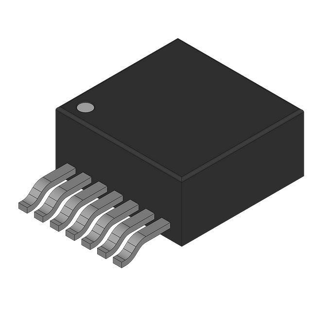
PACKAGE HIGHLIGHTS
•
•
•
(1)
7 Lead Easy-to-use Package (Similar to TO263)
Single Exposed Die Attach Pad for Enhancing
Thermal Performance
10.2 x 13.8 x 4.6 mm Package
CIN
ILED
IIN
High Power LED String
VIN
Figure 1. Typical Application Circuit
EN55015, refer to Figure 36 and Figure 37
1
2
Please be aware that an important notice concerning availability, standard warranty, and use in critical applications of
Texas Instruments semiconductor products and disclaimers thereto appears at the end of this data sheet.
All trademarks are the property of their respective owners.
PRODUCTION DATA information is current as of publication date.
Products conform to specifications per the terms of the Texas
Instruments standard warranty. Production processing does not
necessarily include testing of all parameters.
Copyright © 2012–2013, Texas Instruments Incorporated
�TPS92550
SNVS806C – MAY 2012 – REVISED MAY 2013
www.ti.com
SYSTEM PERFORMANCE
100
EFFICIENCY (%)
ILED(200mA/DIV)
10LED
8LED
6LED
95
90
VDIM(2V/DIV)
85
80
20
24
28
VIN(V)
32
36
4 s/DIV
Figure 2. Efficiency vs VIN , ILED = 350mA
Figure 3. LED Current with PWM Dimming
16µs Dimming Pulse
Figure 4. Radiated Emissions (EN 55015)
Easy to Use 7-Pin Package
(1)
θJA measured on a 1.705” x 3.0” four layer board, with one ounce copper , thirty five 12 mil thermal vias, no air flow,
and 1W power dissipation.
Figure 5. 7-Pin PFM Package
10.16 x 13.77 x 4.57 mm (0.4 x 0.39 x 0.18 in)
θJA = 20°C/W, θJC = 1.9°C/W(1)
RoHS Compliant
2
Submit Documentation Feedback
Copyright © 2012–2013, Texas Instruments Incorporated
Product Folder Links: TPS92550
�TPS92550
www.ti.com
SNVS806C – MAY 2012 – REVISED MAY 2013
CONNECTION DIAGRAM
7
Exposed Pad
Connect to GND
LED-
6
IADJ
5
VREF
4
GND
3
2
DIM
LED+
1
LED+
Figure 6. 7-Pin PFM (Top View)
See NDW0007A Package
PIN DESCRIPTIONS
Pin
Number
Name
1,2
LED+
Anode of LED string
Supply input and rail connection to the anode of the LED string.
3
DIM
Dimming signal input
Dimming control signal input. Open to enable or apply logic level PWM signal
to control the brightness of the LED string.
4
GND
Ground
Reference point for all stated voltages. Connect to the exposed pad of the
package externally.
5
VREF
Voltage reference
Internal voltage reference output.
6
IADJ
LED current adjustment
Fine tunning of the LED current by connecting a resistor between this pin and
ground. Connect this pin to ground for factory preset current.
7
LED-
Cathode of LED string
The current return pin of the LED string, connect to the cathode of the LED
string.
EP
Exposed Pad
Exposed thermal pad
Used to dissipate heat from the package during operation. Must connect to
GND directly.
Description
Function
Submit Documentation Feedback
Copyright © 2012–2013, Texas Instruments Incorporated
Product Folder Links: TPS92550
3
�TPS92550
SNVS806C – MAY 2012 – REVISED MAY 2013
www.ti.com
These devices have limited built-in ESD protection. The leads should be shorted together or the device placed in conductive foam
during storage or handling to prevent electrostatic damage to the MOS gates.
ABSOLUTE MAXIMUM RATINGS
(1)
VALUE / UNITS
LED+, LED- to GND
-0.3V to 40V
DIM to GND
-0.3V to 6V
IADJ, VREF to GND
ESD Susceptibility
-0.3V to 5V
(2)
±2 kV (All pins Except Pin 6)
Power Dissipation
Internally Limited
Junction Temperature
150°C
Storage Temperature Range
0°C to 150°C
Peak Reflow Case Temperature (30 sec)
(1)
(2)
245°C
Absolute Maximum Ratings are limits beyond which damage to the device may occur. Operating Ratings are conditions under which
operation of the device is intended to be functional. For specifications and test conditions, see the Electrical Characteristics.
The human body model is a 100 pF capacitor discharged through a 1.5 kΩ resistor into each pin. The Pin 6 ( IADJ pin) pass ± 1kV.Test
method is per JESD22-AI14S.
RECOMMENDED OPERATING CONDITIONS
(1)
VALUE / UNITS
LED+, LED-
4.5V to 36V
DIM
0V to 5.5V
IADJ
0V to 0.2V
Junction Temperature (TJ)
(1)
4
–40°C to 125°C
Absolute Maximum Ratings are limits beyond which damage to the device may occur. Operating Ratings are conditions under which
operation of the device is intended to be functional. For specifications and test conditions, see the Electrical Characteristics.
Submit Documentation Feedback
Copyright © 2012–2013, Texas Instruments Incorporated
Product Folder Links: TPS92550
�TPS92550
www.ti.com
SNVS806C – MAY 2012 – REVISED MAY 2013
ELECTRICAL CHARACTERISTICS
Limits in standard type are for TJ = 25°C unless otherwise stated; limits in boldface type apply over the operating junction
temperature range TJ of –40°C to 125°C. Minimum and maximum limits are specified through test, design, or statistical
correlation. Typical values represent the most likely parametric norm at TJ = 25°C, and are provided for reference purposes
only. Unless otherwise stated the following conditions apply: VIN =24 V, ILED = 350mA. VIN is the voltage applied across LED+
and GND. IIN is the input current flowing into the LED+ node. ILED is a LED current flowing into the LED- pin. VLED is the
voltage applied across LED+ and LED-. VDIM is the voltage applied across the DIM pin to ground. Resistor RIADJ connect from
IADJ pin to ground. Resistor RVREF connect from VREF pin to ground.
Symbol
Parameter
Conditions
Min
(1)
Typ
(2)
Max
(1)
Units
SYSTEM PARAMETERS
IIN
Input Current
VLED = 0V, 4.5V ≤ VIN ≤ 36V, VDIM = 0V
2.0
2.35
2.7
mA
ILED
LED Current
VLED = 18V, RIADJ = 0Ω, RVREF = open, TJ = 25°C
336
350
361
mA
VLED = 18V, RIADJ = 0Ω, RVREF = open,
TJ = 25°C to 125°C
328
350
361
VLED = 18V, RIADJ = 0Ω, RVREF = open,
TJ = –40°C to 125°C
328
350
370
LED Current at VIN = 36V VIN = 36V, VLED = 24V, RIADJ = 0Ω, RVREF = open,
TJ = 25°C
332
350
359
VIN = 36V, VLED = 24V, RIADJ = 0Ω, RVREF = open,
TJ = 25°C to 125°C
330
350
359
VIN = 36V, VLED = 24V, RIADJ = 0Ω, RVREF = open,
TJ = –40°C to 125°C
330
350
366
VLED = 18V, RIADJ = 0Ω, RVREF = 10.5kΩ , TJ = 25°C
432
450
466
VLED = 18V, RIADJ = 0Ω, RVREF = 10.5kΩ,
TJ = 25°C to 125°C
429
450
466
VLED = 18, V RIADJ = 0Ω, RVREF = 10.5kΩ ,
TJ = –40°C to 125°C
429
450
474
VLED = 18V, RIADJ = 500Ω, RVREF = open,
TJ = 25°C
287
300
309
VLED = 18V, RIADJ = 500Ω, RVREF = open,
TJ = 25°C to 125°C
283
300
309
VLED = 18V, RIADJ = 500Ω, RVREF = open,
TJ = –40°C to 125°C
283
300
315
800
900
1020
mA
1.2
µA
400
450
kHz
1.0
1.2
V
ILED–36V
ILED-ADJ1
ILED-ADJ2
Adjusted LED Current
Adjusted LED Current
ILED-SHORT
LED Short Circuit Current VLED = 0V, VIN = 36V, DIM = open
at VIN = 36V
ILED-LEAK
“LED-” pin leakage
current
VLED = 0V, VIN = operating max, DIM = 0V
fSW
Switching Frequency
VLED = 12V, RIADJ = 0Ω, RVREF = open
VDIM
DIM Pin Threshold
VDIM Increasing
VDIM-HYS
DIM Pin Hysteresis
365
mA
mA
mA
0.25
V
THERMAL CHARACTERISTICS
TSD
Thermal Shutdown
Temperature
TJ Rising
170
°C
TSD-HYS
Thermal Shutdown Temp. TJ Rising
Hysteresis
10
°C
θJA
Junction to Ambient (3)
4 Layer JEDEC Printed Circuit Board, 100 vias, No air flow
19.3
°C/W
2 Layer JEDEC PCB, No air flow
21.5
No air flow
1.9
θJC
(1)
(2)
(3)
Junction to Case
°C/W
Min and Max limits are 100% production tested at an ambient temperature (TA) of 25°C. Limits over the operating temperature range are
specified through correlation using Statistical Quality Control (SQC) methods. Limits are used to calculate Average Outgoing Quality
Level (AOQL).
Typical numbers are at 25°C and represent the most likely parametric norm.
θJA measured on a 1.705” x 3.0” four layer board, with one ounce copper , thirty five 12 mil thermal vias, no air flow, and 1W power
dissipation.
Submit Documentation Feedback
Copyright © 2012–2013, Texas Instruments Incorporated
Product Folder Links: TPS92550
5
�TPS92550
SNVS806C – MAY 2012 – REVISED MAY 2013
www.ti.com
TYPICAL PERFORMANCE CHARACTERISTICS
Unless otherwise specified, the following conditions apply: VIN = 24V, CIN is a 2.2µF 100V X7R ceramic capacitor for driving
2–7 power LEDs with ILED = 350mA. Single LED forward voltage used is 3.2V. TA = 25°C for efficiency curves and waveforms.
Efficiency vs
VIN, ILED = 350mA
ILED Regulation vs
VIN, ILED = 350mA
100
3
3LED
2
4LED
90
ILEDREGULATION (%)
EFFICIENCY (%)
95
85
80
2LED
75
1LED
70
1
4LED
0
1LED
-1
-2
65
60
-3
0
4
8
12 16 20 24 28 32 36
VIN(V)
0
4
8
12 16 20 24 28 32 36
VIN(V)
Figure 7.
Figure 8.
Efficiency vs
VIN, ILED = 350mA
ILED Regulation vs
VIN, ILED = 350mA
100
3
10LED
2
ILEDREGULATION (%)
8LED
EFFICIENCY (%)
3LED
2LED
6LED
95
90
85
6LED
8LED
1
10LED
0
-1
-2
80
-3
20
24
28
VIN(V)
32
36
20
32
Figure 10.
Efficiency vs
VIN, ILED = 450mA
ILED Regulation vs
VIN, ILED = 450mA
36
3
95
3LED
2
4LED
90
ILEDREGULATION (%)
EFFICIENCY (%)
28
VIN(V)
Figure 9.
100
85
80
2LED
75
70
1LED
3LED
1
4LED
2LED
0
-1
1LED
-2
65
60
-3
0
4
8
12 16 20 24 28 32 36
VIN(V)
Figure 11.
6
24
0
4
8
12 16 20 24 28 32 36
VIN(V)
Figure 12.
Submit Documentation Feedback
Copyright © 2012–2013, Texas Instruments Incorporated
Product Folder Links: TPS92550
�TPS92550
www.ti.com
SNVS806C – MAY 2012 – REVISED MAY 2013
TYPICAL PERFORMANCE CHARACTERISTICS (continued)
Unless otherwise specified, the following conditions apply: VIN = 24V, CIN is a 2.2µF 100V X7R ceramic capacitor for driving
2–7 power LEDs with ILED = 350mA. Single LED forward voltage used is 3.2V. TA = 25°C for efficiency curves and waveforms.
Efficiency vs
VIN, ILED = 450mA
ILED Regulation vs
VIN, ILED = 450mA
100
3
10LED
2
ILEDREGULATION (%)
EFFICIENCY (%)
8LED
6LED
95
90
85
6LED
8LED
1
10LED
0
-1
-2
80
-3
20
24
28
VIN(V)
32
36
20
32
Figure 14.
Efficiency vs
VIN, ILED = 300mA
ILED Regulation vs
VIN, ILED = 300mA
36
3
95
3LED
85
80
2LED
75
1LED
70
3LED
2
4LED
90
ILEDREGULATION (%)
EFFICIENCY (%)
28
VIN(V)
Figure 13.
100
2LED
1
4LED
0
1LED
-1
-2
65
60
-3
0
4
8
12 16 20 24 28 32 36
VIN(V)
0
4
8
12 16 20 24 28 32 36
VIN(V)
Figure 15.
Figure 16.
Efficiency vs
VIN, ILED = 300mA
ILED Regulation vs
VIN, ILED = 300mA
100
3
10LED
8LED
6LED
2
ILEDREGULATION (%)
6LED
EFFICIENCY (%)
24
95
90
85
8LED
1
10LED
0
-1
-2
80
-3
20
24
28
VIN(V)
32
36
Figure 17.
20
24
28
VIN(V)
32
36
Figure 18.
Submit Documentation Feedback
Copyright © 2012–2013, Texas Instruments Incorporated
Product Folder Links: TPS92550
7
�TPS92550
SNVS806C – MAY 2012 – REVISED MAY 2013
www.ti.com
TYPICAL PERFORMANCE CHARACTERISTICS (continued)
Unless otherwise specified, the following conditions apply: VIN = 24V, CIN is a 2.2µF 100V X7R ceramic capacitor for driving
2–7 power LEDs with ILED = 350mA. Single LED forward voltage used is 3.2V. TA = 25°C for efficiency curves and waveforms.
LED Current with PWM Dimming
VDIMRising
LED Current with PWM Dimming
VDIMFalling
ILED(200mA/DIV)
ILED(200mA/DIV)
VDIM(2V/DIV)
VDIM(2V/DIV)
2 s/DIV
2 s/DIV
Figure 19.
Figure 20.
LED Current with PWM Dimming
16µs dimming pulse
IIN vs VIN
VDIM = 0V
3.0
ILED(200mA/DIV)
TJ=25°C
2.5
IIN(mA)
2.0
TJ=-40°C
1.5
TJ=125°C
1.0
VDIM(2V/DIV)
0.5
0.0
0
4
8
4 s/DIV
12 16 20 24 28 32 36
VIN(V)
Figure 21.
Figure 22.
IIN vs VIN
LED = open , DIM = open
ILED vs VIN
3LED
3.5
450
TJ=25°C
3.0
400
TJ=-40°C
350
300
2.0
TJ=-40°C
ILED(mA)
IIN(mA)
2.5
TJ=125°C
1.5
TJ=25°C
250
200
TJ=125°C
150
1.0
100
0.5
50
0.0
0
0
4
8
12 16 20 24 28 32 36
VIN(V)
Figure 23.
8
0
4
8
12 16 20 24 28 32 36
VIN(V)
Figure 24.
Submit Documentation Feedback
Copyright © 2012–2013, Texas Instruments Incorporated
Product Folder Links: TPS92550
�TPS92550
www.ti.com
SNVS806C – MAY 2012 – REVISED MAY 2013
TYPICAL PERFORMANCE CHARACTERISTICS (continued)
Unless otherwise specified, the following conditions apply: VIN = 24V, CIN is a 2.2µF 100V X7R ceramic capacitor for driving
2–7 power LEDs with ILED = 350mA. Single LED forward voltage used is 3.2V. TA = 25°C for efficiency curves and waveforms.
ILED vs VIN
VLED = 0V, DIM = open
IIN vs VIN
VLED = 0V, DIM = open
1000
100
TJ=125°C
600
80
IIN(mA)
ILED(mA)
800
TJ=-40°C
400
200
TJ=125°C
60
TJ=-40°C
40
20
TJ=25°C
0
TJ=25°C
0
0
4
8
12 16 20 24 28 32 36
VIN(V)
0
4
8
Figure 25.
Figure 26.
ILED vs Dimming Duty Ratio
ILED vs Dimming Duty Ratio
100
1.0
90
VIN=12V(2LED)
80
70
0.8
VIN=24V(4LED)
60
ILED(%)
ILED(%)
12 16 20 24 28 32 36
VIN(V)
50
40
0.6 VIN=24V(4LED)
0.4
VIN=36V(6LED)
30
VIN=36V(6LED)
20
0.2
10
0
VIN=12V(2LED)
0.0
0 10 20 30 40 50 60 70 80 90 100
DIM DUTY RATIO (%)
0.0
0.2
0.4
0.6
0.8
DIM DUTY RATIO (%)
Figure 27.
Figure 28.
Frequency Deviation vs VIN (400kHz)
ILED Regulation vs Temperature
3
3
2
2
TJ=-40°C
1
ILEDREGULATION (%)
FREQUENCY DEVIATION (%)
1.0
TJ=25°C
0
-1
TJ=125°C
VIN=12V(2LED)
1
0
VIN=36V(6LED)
-1
-2
-2
-3
-3
VIN=24V(4LED)
8
12
16
20
24
VIN(V)
28
32
36
Figure 29.
-50
-25
0
25
50
75
TEMPERATURE (°C)
100 125
Figure 30.
Submit Documentation Feedback
Copyright © 2012–2013, Texas Instruments Incorporated
Product Folder Links: TPS92550
9
�TPS92550
SNVS806C – MAY 2012 – REVISED MAY 2013
www.ti.com
TYPICAL PERFORMANCE CHARACTERISTICS (continued)
Unless otherwise specified, the following conditions apply: VIN = 24V, CIN is a 2.2µF 100V X7R ceramic capacitor for driving
2–7 power LEDs with ILED = 350mA. Single LED forward voltage used is 3.2V. TA = 25°C for efficiency curves and waveforms.
ILED vs RIADJ
RVREF = open
ILED vs RVREF
RIADJ = 0Ω
450
350
425
ILED(mA)
ILED(mA)
340
330
320
375
310
300
350
0
100
200
300
RIADJ( )
400
500
Figure 31.
10
400
0
20
40
60
RVREF(k )
80
100
Figure 32.
Submit Documentation Feedback
Copyright © 2012–2013, Texas Instruments Incorporated
Product Folder Links: TPS92550
�TPS92550
www.ti.com
SNVS806C – MAY 2012 – REVISED MAY 2013
BLOCK DIAGRAM
1,2
LED+
Voltage
Regulator
1 PF
47 PH
7
LED-
High power LED Array
0.33 PF
VCC
VIN
4.5V to 36V
CIN
4
EP
Switch
Control logic
4
GND
6
IADJ
3k
5
VREF
VCC
3
DIM
+
-
1.2V
Operation Description
The TPS92550 is a high power floating buck LED driver with wide input voltage range. It requires no external
current sensing elements and loop compensation network. The integrated power switch enables high output
power up to 14W with 450mA LED current.
High speed dimming control input allows precision and high resolution brightness control for applications which
require fine brightness adjustment.
Submit Documentation Feedback
Copyright © 2012–2013, Texas Instruments Incorporated
Product Folder Links: TPS92550
11
�TPS92550
SNVS806C – MAY 2012 – REVISED MAY 2013
www.ti.com
APPLICATION INFORMATION
SETTING THE LED CURRENT
The TPS92550 requires no external current sensing resistor for LED current regulation. The average LED current
of the TPS92550 is adjustable from 300mA to 450mA by varying the resistance of the resistor according to the
following equation and table.
For RVREF = open and RIADJ = 10.5kΩ
ILED
1050
3k / /R VREF
(2)
Table 1. Example for ILED Setting
RIADJ(Ω)
RVREF(Ω)
ILED(mA)
499
OPEN
300
SHORT
OPEN
350
SHORT
10.5k
450
TPS92550
EP
3
4
5
6
7
LED+
DIM
VREF
GND
IADJ
LED-
LED+
2
1
RIADJ
RVREF
CIN
ILED
IIN
High Power LED String
VIN
Figure 33. TPS92550 Application Schematic for ILED Setting
Minimum Switch On-Time
The on-time of the internal switch should be no shorter than 400ns. The number of LED (typical forward voltage
at 3.2V) to input voltage is constrained by that as shown in the following table.
No. of LED
Max. VIN(V)
1
20
2 – 10
36
Peak Switch Current Limit
The TPS92550 features an integrated switch current limiting mechanism to prevent the LEDs from being overdriven. The switch current limiter is triggered when the switch current is three times exceeding the current level
set by resistor. Once the current limiter is triggered, the internal power switch turn OFF for 3.6µs to discharge the
inductor until inductor current reduces back to normal level. The current limiting feature is exceptionally important
to avoid permanent damage of the TPS92550 application circuit due to short circuit of LED string.
12
Submit Documentation Feedback
Copyright © 2012–2013, Texas Instruments Incorporated
Product Folder Links: TPS92550
�TPS92550
www.ti.com
SNVS806C – MAY 2012 – REVISED MAY 2013
PWM Dimming Control
The DIM pin of the TPS92550 is an input with internal pull-up that accepts logic signals for average LED current
control. Applying a logic high (above 1.2V) signal to the DIM pin or leaving the DIM pin open will enable the
device. Applying a logic low signal (below 0.7V) to the DIM pin will disable the switching activity of the device but
maintain operation of the VCC regulator active. The TPS92550 operation of high speed dimming and very fine
dimming control as shown in Figure 34.
Figure 34. Shortened Current Slew up Time of the TPS92550
To ensure normal operation of the TPS92550, it is recommended to set the dimming frequency not higher than
1/10 of the switching frequency. The dim pulse on time is tested down to 16µs. In applications that require high
dimming contrast ratio, low dimming frequency should be used.
Parallel Operation
When a load current higher than 450mA is required by the application, TPS92550 can be used in parallel to
deliver higher current. With common VINs and GNDs, the TPS92550 will operate as independent asynchronous
current sinks driving the same LED load. The total DC current of the modules will be additive; however, low
frequency sub-harmonic current ripple may be present and its frequency and magnitude will depend upon the
phase relationship between the internal clocks as there is no provision for synchronizing driver clocks. It is
suggested to have minimum 2.2μF COUT located close to the module to filter out the current ripple, and the
resultant LED current will become DC. Current sharing modules should have a local CIN capacitor of minimum
2.2μF located as close to VIN and GND as possible. Refer to Figure 35 for the TPS92550 parallel operation
circuit schematic. Refer to Figure 36 for the TPS92550 parallel operation results ILED vs VIN.
VIN
ILED1
CIN
COUT
IADJ 6
LED- 7
VREF 5
DIM 3
LED+ 1
LED+ 2
COUT
LED- 7
VREF 5
IADJ 6
DIM 3
GND 4
GND 4
EP
EP
LED+ 1
LED+ 2
ILED
TPS92550
High Power LED String
TPS92550
ILED2
CIN
Figure 35. Parallel Operation Circuit Schematic for ILED = 900mA
Submit Documentation Feedback
Copyright © 2012–2013, Texas Instruments Incorporated
Product Folder Links: TPS92550
13
�TPS92550
SNVS806C – MAY 2012 – REVISED MAY 2013
www.ti.com
1.0
0.9
0.8
1LED
5LED
ILED(A)
0.7
0.6
0.5
0.4
10LED
0.3
0.2
0.1
0.0
0
10
20
VIN(V)
30
40
Figure 36. Parallel Operation Results for ILED = 900mA, ILED vs VIN
PC Board Layout Considerations
The overall performance of the LED driver is highly depends on the PCB layout. Poor board layout can disrupt
the performance of the TPS92550 and surrounding circuitry by contributing to EMI, ground bounce and resistive
voltage drop in the traces. These can send erroneous signals to the LED driver resulting in poor regulation and
stability. Good layout can be implemented by following a few simple design rules.
1. Place CIN as close as possible to the VIN pin and GND exposed pad (EP).
2. Place COUT (optional for reduction of LED current ripple and EMI compliance) as close as possible to the
VLED+ pin and VLED- pin.
3. The exposed pad (EP) must connect to the GND pin directly.
EMI Design Considerations
From an EMI reduction standpoint, it is imperative to minimize the di/dt current paths (refer to Figure 37).
Therefore, it is essential to connect an 2.2µF capacitor (COUT) across the LED+ pin and LED- pin. This will
minimize the ripple current so that it can reduce radiated EMI (refer to Figure 38 and Figure 39).
High power LED Array
COUT
di/dt
Loop 2
VIN
LED+
LED-
TPS92550
CIN
GND
Loop1
Figure 37. Current Loops
14
Submit Documentation Feedback
Copyright © 2012–2013, Texas Instruments Incorporated
Product Folder Links: TPS92550
�TPS92550
www.ti.com
SNVS806C – MAY 2012 – REVISED MAY 2013
Figure 38. Complies with EN55015 Radiated
Emissions (HORI. / HEIGHT=3.0m / RANGE=10m)
CIN = 2.2µF, COUT = 2.2uF, VIN = 36V, ILED = 350mA,
No. of LED = 10
Figure 39. Complies with EN55015 Radiated
Emissions (VERT. / HEIGHT=1.0m / RANGE=10m)
CIN = 2.2µF, COUT = 2.2uF, VIN = 36V , ILED = 350mA,
No. of LED = 10
TPS92550 Application Circuit Schematic and BOM
High power LED Array
U1
VIN
1,2
7
LED+
LED-
PWM
Dimming
Signal
TPS92550
CIN
2.2 PF
100V
DIM
IADJ
GND
6
3
VREF
4,EP
5
Table 2. Bill of Materials, VIN = 18V , ILED = 350mA, No. of LED = 2 — 5
Designator
Description
Case Size
Manufacturer
Manufacturer P/N
Quantity
U1
LED Micro-Module Driver
PFM
Texas Instruments
TPS92550TZ
1
CIN
2.2 µF, 100V, X7R
1210
Murata
GRM32ER72A225KA35L
1
High power LED Array
COUT
2.2 PF 100V
U1
VIN
1,2
LED+
LED-
7
PWM
Dimming
Signal
TPS92550
CIN
2.2 PF
100V
DIM
IADJ
6
GND
4,EP
3
VREF
5
Table 3. Bill of Materials, VIN = 36V , ILED = 350mA , No.of LED = 10, Complies with EN55015 Radiated
Submit Documentation Feedback
Copyright © 2012–2013, Texas Instruments Incorporated
Product Folder Links: TPS92550
15
�TPS92550
SNVS806C – MAY 2012 – REVISED MAY 2013
www.ti.com
Table 3. Bill of Materials, VIN = 36V , ILED = 350mA , No.of LED = 10, Complies with EN55015 Radiated
Emissions (continued)
Emissions
Designator
Description
Case Size
Manufacturer
Manufacturer P/N
Quantity
U1
LED Micro-Module Driver
PFM
Texas Instruments
TPS92550TZ
1
CIN
2.2 µF, 100V, X7R
1210
Murata
GRM32ER72A225KA35L
1
COUT
2.2 µF, 100V, X7R
1210
Murata
GRM32ER72A225KA35L
1
PCB Layout Diagrams
The PCB design is available in the TPS92550 product folder at www.ti.com.
Figure 40. Top Layer and Top Overlay
16
Submit Documentation Feedback
Copyright © 2012–2013, Texas Instruments Incorporated
Product Folder Links: TPS92550
�TPS92550
www.ti.com
SNVS806C – MAY 2012 – REVISED MAY 2013
Figure 41. Bottom Layer and Bottom Overlay
Submit Documentation Feedback
Copyright © 2012–2013, Texas Instruments Incorporated
Product Folder Links: TPS92550
17
�TPS92550
SNVS806C – MAY 2012 – REVISED MAY 2013
www.ti.com
Figure 42. Top Overlay
18
Submit Documentation Feedback
Copyright © 2012–2013, Texas Instruments Incorporated
Product Folder Links: TPS92550
�TPS92550
www.ti.com
SNVS806C – MAY 2012 – REVISED MAY 2013
REVISION HISTORY
Changes from Revision B (May 2013) to Revision C
•
Page
Changed layout of National Data Sheet to TI format .......................................................................................................... 18
Submit Documentation Feedback
Copyright © 2012–2013, Texas Instruments Incorporated
Product Folder Links: TPS92550
19
�PACKAGE OPTION ADDENDUM
www.ti.com
16-Jul-2020
PACKAGING INFORMATION
Orderable Device
Status
(1)
Package Type Package Pins Package
Drawing
Qty
Eco Plan
(2)
Lead finish/
Ball material
MSL Peak Temp
Op Temp (°C)
Device Marking
(3)
(4/5)
(6)
TPS92550TZ/NOPB
ACTIVE
TO-PMOD
NDW
7
250
RoHS Exempt
& Green
SN
Level-3-245C-168 HR
-40 to 125
TPS92550
TZ
TPS92550TZX/NOPB
ACTIVE
TO-PMOD
NDW
7
500
RoHS Exempt
& Green
SN
Level-3-245C-168 HR
-40 to 125
TPS92550
TZ
(1)
The marketing status values are defined as follows:
ACTIVE: Product device recommended for new designs.
LIFEBUY: TI has announced that the device will be discontinued, and a lifetime-buy period is in effect.
NRND: Not recommended for new designs. Device is in production to support existing customers, but TI does not recommend using this part in a new design.
PREVIEW: Device has been announced but is not in production. Samples may or may not be available.
OBSOLETE: TI has discontinued the production of the device.
(2)
RoHS: TI defines "RoHS" to mean semiconductor products that are compliant with the current EU RoHS requirements for all 10 RoHS substances, including the requirement that RoHS substance
do not exceed 0.1% by weight in homogeneous materials. Where designed to be soldered at high temperatures, "RoHS" products are suitable for use in specified lead-free processes. TI may
reference these types of products as "Pb-Free".
RoHS Exempt: TI defines "RoHS Exempt" to mean products that contain lead but are compliant with EU RoHS pursuant to a specific EU RoHS exemption.
Green: TI defines "Green" to mean the content of Chlorine (Cl) and Bromine (Br) based flame retardants meet JS709B low halogen requirements of