User's Guide
SLWU056 – June 2008
TRF3762 EVM User's Guide
Contents
1
Hardware Setup .............................................................................................................. 1
2
Software Setup ............................................................................................................... 2
Appendix A
Synthesizing Desired Frequencies ............................................................................. 10
Appendix B
Output Configuration Options ................................................................................... 11
Appendix C TRF3762 QFN Installation Using a Hakko Hot Air Rework Station ........................................ 12
List of Figures
1
Single Output Without Balun
..............................................................................................
2
List of Tables
1
1
Required Test Hardware .................................................................................................... 1
Hardware Setup
This manual can help users to operate the TRF3762 evaluation module (EVM) with the supplied software.
The required hardware for testing the EVM is listed in Table 1.
Table 1. Required Test Hardware
Hardware
Specifications
Power supply (1)
Spectrum analyzer (1)
Units
4.5 to 5.2
V
0 to 6 Spurs
–160 resolution (phase noise)
GHz
dBm
Agilent’s 5052 (1)
Low phase noise reference source (1)
Personal computer (PC) (1)
Power cable (1)
Parallel-to-parallel connector cable(1)
Coaxial cable (2)
1 kHz
–120.22
100 kHz
–145.6
590 kHz
–158
1 MHz
–158
3 MHz
–160
5 MHz
–161
Rms jitter
236.69
dBc
ps
2-GHz processor, CD drive, Parallel port
Supplied by Texas Instruments
Not supplied by Texas Instruments
DB25 to DB25
50
Ω
X-ACTO is a trademark of Elmer's Products, Inc..
LabVIEW is a trademark of National Instruments Corporation.
SLWU056 – June 2008
Submit Documentation Feedback
TRF3762 EVM User's Guide
1
�Software Setup
www.ti.com
To achieve the test data, all hardware that is supplied with EVM is required. TRF3762 measured
performance depends on the phase noise characteristics of the reference source used as well as the
resolution of the hardware used for phase noise measurements.
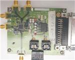
The setup of the device is simple. See Figure 1.
Differential RF out
Not connected.
To spectrum analyzer or Agilent 5052
Single ended RF out
DC input for
Open loop test
DB25 TO PC
Reference input
To low phase noise
Reference.
Power supply
Connection
To power supply.
Figure 1. Single Output Without Balun
The board shown in Figure 1 has a 3-dB lower output power when configured as a single-ended output,
approximately 0 dBm. When converting to a differential output by removing the 50-Ω resistor R32 in the
differential path the output power should increase by 3-dB minus the balun losses. Components can be
added to achieve a tuned reactive load which improves the output power. See Appendix B for output
configuration options.
The following items are provided in the TRF3762EVM kit.
• CD-ROM
• EVM board
• Power cable
• Programming cable
2
Software Setup
The LabVIEW™ software provided by Texas Instruments on the accompanying CD is the software that
configures the TRF3762. It is used to set the registers inside the device for normal operation. The
LabVIEW software interfaces to the EVM via a DB25 connector. The chip uses a SPI interface protocol
with data formatted as little endian, which means the LSB is clocked in first.
2
TRF3762 EVM User's Guide
SLWU056 – June 2008
Submit Documentation Feedback
�Software Setup
www.ti.com
2.1
Software Installation
When loaded, the CD that accompanies the EVM displays on the PC monitor either a folder with a date for
a file name or the full folder of files.
Or
In either case, find the installer folder. This is the folder containing the program and its support files. Once
found, open the installer folder, and the following screen displays.
SLWU056 – June 2008
Submit Documentation Feedback
TRF3762 EVM User's Guide
3
�Software Setup
www.ti.com
TI recommends that all files in the installer folder be copied to one folder on the PC or laptop that will be
running the program before installing it. Do this by clicking on the installer folder and dragging it to the PC.
Once the folder installer has been copied on the computer, open it and find the LabVIEW runtime engine
setup.exe file. Double-click it ,and execute the program by following the on-screen prompts.
4
TRF3762 EVM User's Guide
SLWU056 – June 2008
Submit Documentation Feedback
�Software Setup
www.ti.com
C:\Customers Computer
Once the LabVIEW runtime engine is installed, go back to the installer folder and create a folder called
accessHW.
New folder
Open the accessHW.zip file. This file contains the software to set up the port on the PC.
Extract all files in the zip folder to the folder you created (accessHW). The files should look like the
following.
SLWU056 – June 2008
Submit Documentation Feedback
TRF3762 EVM User's Guide
5
�Software Setup
www.ti.com
Double-click on the setup.exe file, and run the setup of the port. You are prompted for which object or
library to use.
Select Microsoft Visual C++ 2x, 4x, and then click Next. Follow the prompts.
Once the program is installed, open it and you should see the following display.
6
TRF3762 EVM User's Guide
SLWU056 – June 2008
Submit Documentation Feedback
�www.ti.com
Software Setup
This is the main control screen to use for programming the TRF3762; the frequency of interest is under
the tab labeled Top Level App.
SLWU056 – June 2008
Submit Documentation Feedback
TRF3762 EVM User's Guide
7
�Software Setup
2.2
www.ti.com
The Controls
The left side of the main control screen is where inputs can be adjusted.
Make sure this button’s indicator is green.
Make sure this button ’s indicator is green.
Type in the frequency of your reference in MHz.
Type in the step frequency you require.
Use the spinner buttons to adjust the divide by ratio.
Use the spinner buttons to set.
Type in the value of R27 on the board.
Type in the frequency of interest.
Use spinner buttons to change the frequency divider.
Use execute button to run program.
Shows the output frequency of TRF3761
•
•
•
•
•
•
•
•
•
8
Fcrystal is the reference used on the EVM. It can between 10 MHz to 104 MHz.
Fpfd is the phase frequency detector frequency and sets the frequency step size. For example, if the
main frequency is 2000 MHz and the Fpfd is 200 kHz, then the next frequency step can be 2000.2
MHz.
Prescalar Div Ratio is the ratio used in the Fout equation, Fout = Fpfd (A+PB), where the numerator of
the Prescalar Div Ratio is equal to P, and A and B are calculated. For more information, see Appendix
A.
Rbias is used for a calculation which is on the right side of the Main Control Screen in the window
Icp(Rbias).The value of Rbias is set to the same value as R27 on the EVM board is 2.73 kΩ. The
resistor value can be changed on the board if a different charge pump current is desired.
Icp sets the amount of current on the charge pump as well. Eight setting are used to increase and
decrease the current; they are 0.7, 1.4, 2.1, 2.8, 3.5, 4.2, 4.9, and 5.6. These numbers represent the
current seen if a 4.75-kΩ resistor is used. The calculation to determine the desired Icpactual is
[Icp(4.75k)]/Rbias = Icpactual, which should give the same answer as the Icp(Rbias) on the right side
calculations.
Fvco is the output frequency of VCO.
Output Mode sets the frequency divider. For example, if 500 MHz is required, then set the Fvco to
2000 MHz and the Output Mode to “/4”.
The Selected Output window at the bottom by the Execute button shows the output frequency that the
user sets up.
To enter the data into the TRF3762, press the Execute button. Once pressed, the output changes to
the frequency shown in the Selected Output window.
TRF3762 EVM User's Guide
SLWU056 – June 2008
Submit Documentation Feedback
�Software Setup
www.ti.com
2.3
The Calculations
The right side of the main control screen shows the system setup calculations.
•
•
•
•
•
•
•
•
•
•
•
FREF is the reference oscillator frequency in MHz.
Fref_Frac is not used.
RDIV is the number the reference frequency is divided by to get Fpfd.
NDIV is the number the output frequency is divided by to get Fpfd.
A and B are the variables in the equation Fout = Fpfd (A+PB) as discussed in the prescalar section of
the controls. See Appendix A.
Fout is the actual frequency out.
Fvco 1x is the undivided frequency out of the VCO.
Fvco DIV2 is the frequency out of the VCO divided by 2.
Fvco DIV4 is the frequency out of the VCO divided by 4.
Spur offset is the offset of the phase frequency detector spur.
Icp (Rbias) is the actual current of the charge pump. Calculated from [Icp(4.75k)]/Rbias = Icpactual.
SLWU056 – June 2008
Submit Documentation Feedback
TRF3762 EVM User's Guide
9
�Appendix A
www.ti.com
Appendix A Synthesizing Desired Frequencies
Prescalar Div is a multiselection dual modulus to limit the frequency of the Prescalar to below 250
MHz. The setting are 8/9, 6/17, 32/33, and 64/65. The TRF3762 has an integer-N PLL synthesizer,
and because of its flexibility (14-bit R, 6-bit A, 13-bit B counter, and dual modulus prescalar), is
ideal for synthesizing virtually any desired frequency. Assume that one needs to synthesize a
900-MHz local oscillator, with spacing capability (minimum frequency increment) of 200 kHz, as in a
typical GSM application. The choice of the external reference oscillator to be used is beyond the
scope of this user's guide, but assuming that a 10-MHz reference is selected, one can calculate the
settings that yield the desired output frequency and channel spacing. Although more than one
solution can often apply to a specific set of conditions, the following is one means of achieving the
desired result.
First, select the appropriate R counter value. Because a channel spacing of 200 kHz is desired, the
PFD can also be set to 200 kHz. Calculate the R value through R = REFIN/PFD = 10 MHz/ 200
kHz = 50. Assume that a prescalar value of 8/9 is selected. This is a valid choice because the
prescalar output will be well within the 200-MHz limit (900 MHz / 8 = 112.5 MHz). Select the
appropriate A and B counter values. It is known that RFOUT = Fpfd × N = (FREFIN / R) × (A + P ×
B). Therefore, solve the following equation:
900 MHz = 200 kHz x (A + 8 x B)
Clearly, many solutions exist for this single equation with two unknowns; however, because 3 ≤ B ≤
8191, and also B ≥ A, there are some basic constraints on the solution. So, if A = 4, solving the
equation yields B = 562. Thus, one complete solution would be to choose: R = 50, A = 4, B = 562,
and P = 8/9, resulting in the desired N = 4500.
10
Synthesizing Desired Frequencies
SLWU056 – June 2008
Submit Documentation Feedback
�Appendix B
www.ti.com
Appendix B Output Configuration Options
Single/Differential
Output Configurations
Load
Pout
Single-ended
Differential 50-Ω shunt
Resistive
0
Single-ended
Differential 50-Ω shunt
Tuned (LC)
3
Differential
External balun
Resistive
3
Differential
External balun
Tuned (LC)
6
SLWU056 – June 2008
Submit Documentation Feedback
Output Configuration Options
11
�Appendix C
www.ti.com
Appendix C TRF3762 QFN Installation Using a Hakko Hot Air Rework Station
The TRF3762 devices are optionally sampled separately from the board (TRF3671EVM-X). This guideline
is designed to help the person evaluating these parts to install the sample device on the board provided.
The EVM board has an immersion gold plating. Due to gold leaching into the solder joint, it is a best
practice to tin the pads and wick off the extra solder. Using a solder with silver content helps but is
unnecessary.
Apply solder paste to each pad including the center ground; do not skimp when applying paste to the
center ground. It is recommended to use a type 6 Sn62Pb36Ag2 alloy with an 82% loading in an EFD
dispensing system; solder paste can be applied manually with a dental pick.
Under a microscope, place the device inside the square silkscreen labeled U2. Pin 1 of the device is
designated by a round dot on the package; pin 1 on the board is designated by an asterisk and a slightly
mitered corner.
Use a tool like a dental pick or the point of a hobby knife (like an X-ACTO™ knife) to position the part so
that the device leads are centered on the traces. The solder paste may smear; this is not an issue at this
point.
Place the board in the Hakko Omnivise, and position it over the Hakko preheater. With the preheater set
at 200°C, let the part heat up for 30 seconds. Place the Hakko hot air nozzle (A1130, this is a 0,44-mm
diameter nozzle) over the device. With the temperature set at 343°C and the air flow set at 15
liters/minute, turn on the hot air rework station. This setting can be adjusted lower if adjacent components
are being disturbed. Letting the board thermally soak over the preheater along with letting the hot air come
up to temperature while blowing on the part provides a thermal ramp profile. This helps to ensure a good
solder joint.
Watch the device as it heats up; when the solder paste reflows, let the part continue to heat for 15
seconds. Remove it from the heat. Inspect the part immediately, and verify that there are no solder shorts
and that there is connection at all pins. A soldering iron with a tip radius of 0.008 at 370°C works well for
this; add extra flux when doing rework.
To clean the flux residue from the board: spray the board with a flux cleaner, lay a thin absorbent tissue
over the board, and brush the board through the tissue. The absorbent tissue wicks up the
flux-contaminated solvent. Blow the board dry with compressed air. If spurs are present, additional
cleaning in an ultrasonic cleaner and subsequent baking may be necessary.
C.1
USEFUL LINKS
Hakko Products:
http://www.hakkousa.com/2006/default_1.asp?Assistant=Dinky
Solder Paste, Flux, Dispenser:
http://www.efd-inc.com/mikros/index.html
http://www.efdsolder.com/
12
TRF3762 QFN Installation Using a Hakko Hot Air Rework Station
SLWU056 – June 2008
Submit Documentation Feedback
�EVALUATION BOARD/KIT IMPORTANT NOTICE
Texas Instruments (TI) provides the enclosed product(s) under the following conditions:
This evaluation board/kit is intended for use for ENGINEERING DEVELOPMENT, DEMONSTRATION, OR EVALUATION PURPOSES
ONLY and is not considered by TI to be a finished end-product fit for general consumer use. Persons handling the product(s) must have
electronics training and observe good engineering practice standards. As such, the goods being provided are not intended to be complete
in terms of required design-, marketing-, and/or manufacturing-related protective considerations, including product safety and environmental
measures typically found in end products that incorporate such semiconductor components or circuit boards. This evaluation board/kit does
not fall within the scope of the European Union directives regarding electromagnetic compatibility, restricted substances (RoHS), recycling
(WEEE), FCC, CE or UL, and therefore may not meet the technical requirements of these directives or other related directives.
Should this evaluation board/kit not meet the specifications indicated in the User’s Guide, the board/kit may be returned within 30 days from
the date of delivery for a full refund. THE FOREGOING WARRANTY IS THE EXCLUSIVE WARRANTY MADE BY SELLER TO BUYER
AND IS IN LIEU OF ALL OTHER WARRANTIES, EXPRESSED, IMPLIED, OR STATUTORY, INCLUDING ANY WARRANTY OF
MERCHANTABILITY OR FITNESS FOR ANY PARTICULAR PURPOSE.
The user assumes all responsibility and liability for proper and safe handling of the goods. Further, the user indemnifies TI from all claims
arising from the handling or use of the goods. Due to the open construction of the product, it is the user’s responsibility to take any and all
appropriate precautions with regard to electrostatic discharge.
EXCEPT TO THE EXTENT OF THE INDEMNITY SET FORTH ABOVE, NEITHER PARTY SHALL BE LIABLE TO THE OTHER FOR ANY
INDIRECT, SPECIAL, INCIDENTAL, OR CONSEQUENTIAL DAMAGES.
TI currently deals with a variety of customers for products, and therefore our arrangement with the user is not exclusive.
TI assumes no liability for applications assistance, customer product design, software performance, or infringement of patents or
services described herein.
Please read the User’s Guide and, specifically, the Warnings and Restrictions notice in the User’s Guide prior to handling the product. This
notice contains important safety information about temperatures and voltages. For additional information on TI’s environmental and/or
safety programs, please contact the TI application engineer or visit www.ti.com/esh.
No license is granted under any patent right or other intellectual property right of TI covering or relating to any machine, process, or
combination in which such TI products or services might be or are used.
FCC Warning
This evaluation board/kit is intended for use for ENGINEERING DEVELOPMENT, DEMONSTRATION, OR EVALUATION PURPOSES
ONLY and is not considered by TI to be a finished end-product fit for general consumer use. It generates, uses, and can radiate radio
frequency energy and has not been tested for compliance with the limits of computing devices pursuant to part 15 of FCC rules, which are
designed to provide reasonable protection against radio frequency interference. Operation of this equipment in other environments may
cause interference with radio communications, in which case the user at his own expense will be required to take whatever measures may
be required to correct this interference.
EVM WARNINGS AND RESTRICTIONS
It is important to operate this EVM within the input voltage range of 4.5 V to 5.25 V.
Exceeding the specified input range may cause unexpected operation and/or irreversible damage to the EVM. If there are questions
concerning the input range, please contact a TI field representative prior to connecting the input power.
Applying loads outside of the specified output range may result in unintended operation and/or possible permanent damage to the EVM.
Please consult the EVM User's Guide prior to connecting any load to the EVM output. If there is uncertainty as to the load specification,
please contact a TI field representative.
During normal operation, some circuit components may have case temperatures greater than 40°C. The EVM is designed to operate
properly with certain components above 40°C as long as the input and output ranges are maintained. These components include but are
not limited to linear regulators, switching transistors, pass transistors, and current sense resistors. These types of devices can be identified
using the EVM schematic located in the EVM User's Guide. When placing measurement probes near these devices during operation,
please be aware that these devices may be very warm to the touch.
Mailing Address: Texas Instruments, Post Office Box 655303, Dallas, Texas 75265
Copyright 2006, Texas Instruments Incorporated
�IMPORTANT NOTICE
Texas Instruments Incorporated and its subsidiaries (TI) reserve the right to make corrections, modifications, enhancements, improvements,
and other changes to its products and services at any time and to discontinue any product or service without notice. Customers should
obtain the latest relevant information before placing orders and should verify that such information is current and complete. All products are
sold subject to TI’s terms and conditions of sale supplied at the time of order acknowledgment.
TI warrants performance of its hardware products to the specifications applicable at the time of sale in accordance with TI’s standard
warranty. Testing and other quality control techniques are used to the extent TI deems necessary to support this warranty. Except where
mandated by government requirements, testing of all parameters of each product is not necessarily performed.
TI assumes no liability for applications assistance or customer product design. Customers are responsible for their products and
applications using TI components. To minimize the risks associated with customer products and applications, customers should provide
adequate design and operating safeguards.
TI does not warrant or represent that any license, either express or implied, is granted under any TI patent right, copyright, mask work right,
or other TI intellectual property right relating to any combination, machine, or process in which TI products or services are used. Information
published by TI regarding third-party products or services does not constitute a license from TI to use such products or services or a
warranty or endorsement thereof. Use of such information may require a license from a third party under the patents or other intellectual
property of the third party, or a license from TI under the patents or other intellectual property of TI.
Reproduction of TI information in TI data books or data sheets is permissible only if reproduction is without alteration and is accompanied
by all associated warranties, conditions, limitations, and notices. Reproduction of this information with alteration is an unfair and deceptive
business practice. TI is not responsible or liable for such altered documentation. Information of third parties may be subject to additional
restrictions.
Resale of TI products or services with statements different from or beyond the parameters stated by TI for that product or service voids all
express and any implied warranties for the associated TI product or service and is an unfair and deceptive business practice. TI is not
responsible or liable for any such statements.
TI products are not authorized for use in safety-critical applications (such as life support) where a failure of the TI product would reasonably
be expected to cause severe personal injury or death, unless officers of the parties have executed an agreement specifically governing
such use. Buyers represent that they have all necessary expertise in the safety and regulatory ramifications of their applications, and
acknowledge and agree that they are solely responsible for all legal, regulatory and safety-related requirements concerning their products
and any use of TI products in such safety-critical applications, notwithstanding any applications-related information or support that may be
provided by TI. Further, Buyers must fully indemnify TI and its representatives against any damages arising out of the use of TI products in
such safety-critical applications.
TI products are neither designed nor intended for use in military/aerospace applications or environments unless the TI products are
specifically designated by TI as military-grade or "enhanced plastic." Only products designated by TI as military-grade meet military
specifications. Buyers acknowledge and agree that any such use of TI products which TI has not designated as military-grade is solely at
the Buyer's risk, and that they are solely responsible for compliance with all legal and regulatory requirements in connection with such use.
TI products are neither designed nor intended for use in automotive applications or environments unless the specific TI products are
designated by TI as compliant with ISO/TS 16949 requirements. Buyers acknowledge and agree that, if they use any non-designated
products in automotive applications, TI will not be responsible for any failure to meet such requirements.
Following are URLs where you can obtain information on other Texas Instruments products and application solutions:
Products
Amplifiers
Data Converters
DSP
Clocks and Timers
Interface
Logic
Power Mgmt
Microcontrollers
RFID
RF/IF and ZigBee® Solutions
amplifier.ti.com
dataconverter.ti.com
dsp.ti.com
www.ti.com/clocks
interface.ti.com
logic.ti.com
power.ti.com
microcontroller.ti.com
www.ti-rfid.com
www.ti.com/lprf
Applications
Audio
Automotive
Broadband
Digital Control
Medical
Military
Optical Networking
Security
Telephony
Video & Imaging
Wireless
www.ti.com/audio
www.ti.com/automotive
www.ti.com/broadband
www.ti.com/digitalcontrol
www.ti.com/medical
www.ti.com/military
www.ti.com/opticalnetwork
www.ti.com/security
www.ti.com/telephony
www.ti.com/video
www.ti.com/wireless
Mailing Address: Texas Instruments, Post Office Box 655303, Dallas, Texas 75265
Copyright © 2008, Texas Instruments Incorporated
�