UCD7230A
www.ti.com
SLUS995 – NOVEMBER 2009
Digital Control Compatible Synchronous Buck Gate Driver
with Current Sense Conditioning Amplifier
Check for Samples: UCD7230A
FEATURES
APPLICATIONS
•
•
1
2
•
•
•
•
•
•
•
•
•
Input from Digital Controller Sets Operating
Frequency and Duty Cycle
Up to 2-MHz Switching Frequency
Dual Current Limit Protection with
Independently Adjustable Thresholds
Fast Current Sense Circuit with Adjustable
Blanking Interval Prevents Catastrophic
Current Levels
Digital Output Current Limit Flag
Low Offset, Gain of 48, Differential Current
Sense Amplifier
3.3-V, 10-mA Internal Regulator
Dual TrueDrive™ High-Current Drivers
10-ns Typical Rise/Fall Times with 2.2-nF
Loads
4.5-V to 15.5-V Supply Voltage Range
•
•
•
Digitally-Controlled Synchronous-Buck Power
Stages for Single and Multi-Phase
Applications
Especially Suited for Use with UCD91xx or
UCD92xx Contollers
High-Current Multi-Phase VRM/EVRD
Regulators for Desktop, Server, Telecom and
Notebook Processors
Digitally-Controlled Synchronous-Buck Power
Supplies Using μCs or the TMS320™ DSP
Family
DESCRIPTION
The UCD7230A is one in the UCD7k family of digital
control compatible drivers for applications utilizing
digital control techniques or applications requiring fast
local peak current limit protection.
The UCD7230A is a MOSFET gate driver specifically
designed for synchronous buck applications. It is
ideally suited to provide the bridge between digital
controllers such as the UCD91xx or the UCD92xx
and the power stage. With cycle-by-cycle current limit
protection, the UCD7230A device protects the power
stage from faulty input signals or excessive load
currents.
VIN
VOUT
18
16
17
VDD CSBIAS CS+
BIAS
1
2
13
14
BST OUT1
15
SW
3V3
AGND
UCD7230A
IMAX
4
ILIM
CLF
5
CLF
12
11
10
PVDD OUT2 PGND
POS
8
NEG
9
AO
7
ILOAD
IN 20
PWM
SRE 19
IO
6
DLY
3
SRE
IDLY
UDG-09162
1
2
Please be aware that an important notice concerning availability, standard warranty, and use in critical applications of Texas
Instruments semiconductor products and disclaimers thereto appears at the end of this data sheet.
TMS320, TrueDrive are trademarks of Texas Instruments.
PRODUCTION DATA information is current as of publication date.
Products conform to specifications per the terms of the Texas
Instruments standard warranty. Production processing does not
necessarily include testing of all parameters.
Copyright © 2009, Texas Instruments Incorporated
�UCD7230A
SLUS995 – NOVEMBER 2009
www.ti.com
This integrated circuit can be damaged by ESD. Texas Instruments recommends that all integrated circuits be handled with
appropriate precautions. Failure to observe proper handling and installation procedures can cause damage.
ESD damage can range from subtle performance degradation to complete device failure. Precision integrated circuits may be more
susceptible to damage because very small parametric changes could cause the device not to meet its published specifications.
DESCRIPTION (CONTINUED)
The UCD7230A includes high-side and low-side gate drivers which utilize Texas Instrument’s TrueDrive™ output
architecture. This architecture delivers rated current into the gate capacitance of a MOSFET during the Miller
plateau region of the switching. Furthermore, the UCD7230A offers a low offset differential amplifier with a fixed
gain of 48. This amplifier greatly simplifies the task of conditioning small current sense signals inherent in high
efficiency buck converters.
The UCD7230A includes a 3.3-V, 10-mA linear regulator to provide power to digital controllers such as the
UCD91xx. The UCD7230A is compatible with standard 3.3-V I/O ports of the UCD91xx, the TMS320™ family
DSPs, microprocessors, or ASICs.
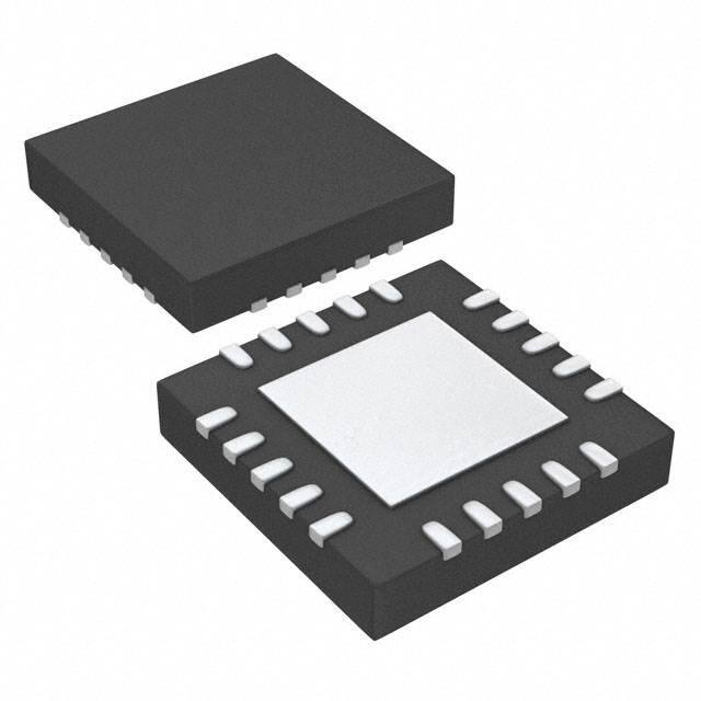
The UCD7230A is offered in the space-saving QFN package. Package pin out has been carefully designed for
optimal board layout
ORDERING INFORMATION (1)
TEMPERATURE RANGE
-40°C to + 125°C
(1)
(2)
2
PACKAGED DEVICES
QFN-20 (RGW)
(2)
PACKAGE QUANTITY
DELIVERY MEDIA
DEVICE NUMBER
250
Small tape and reel
UCD7230ARGWT
3000
Large tape and reel
UCD7230ARGWR
These products are packaged in Pb-Free and green lead finish of Pd-Ni-Au which is compatible with MSL level 1 between 255°C and
260°C peak reflow temperature to be compatible with either lead free or Sn/Pb soldering operations.
QFN-20 (RGW) package is available taped and reeled only.
Submit Documentation Feedback
Copyright © 2009, Texas Instruments Incorporated
Product Folder Link(s): UCD7230A
�UCD7230A
www.ti.com
SLUS995 – NOVEMBER 2009
ABSOLUTE MAXIMUM RATINGS (1)
over operating free-air temperature range (unless otherwise noted)
MIN
Input voltage
Supply current
Output gate drive voltage
Output gate drive current
MAX
VDD
16
BST
VSW+16 V
VDD
20
OUT1
200
OUT1, BST
-1
36
OUT2
-1
VVDD+0.3
OUT1 (sink)
4.0
OUT1 (source)
-2.0
OUT2 (sink)
4.0
OUT2 (source)
UNIT
V
mA
V
A
-4.0
SW
-1
20
CS+
-0.3
20
CSBIAS
-0.3
16
POS, NEG
-0.3
5.6
ILIM, DLY, I0
-0.3
3.6
Analog output
A0
-0.3
3.6
Digital I/O’s
IN, SRE, CLF
-0.3
3.6
V
2
kV
500
V
Analog input voltage
Electrostatic discharge, human body model(HBM)
Electrostatic discharge, charged device model (CDM)
V
Operating junction temperature, TJ
-55
150
Storage temperature, Tstg
-65
150
Lead temperature (soldering, 10 sec)
(1)
V
°C
300
°C
Stresses beyond those listed in this table may cause permanent damage to the device. These are stress ratings only and functional
operation of the device at these or any other condition beyond those indicated is not implied. Exposure to absolute maximum rated
conditions for extended periods may affect device reliability. All voltages are with respect to GND. Currents are positive into, negative
out of the specified terminal. Consult company packaging information for thermal limitations and considerations of packages.
RECOMMENDED OPERATING CONDITIONS
over operating free-air temperature range (unless otherwise noted)
MIN
TYP
MAX
4.75
12
15
Switching Frequency
200
500
2000
kHz
Operating ambient temperature
-40
85
°C
Input voltage
TA
VDD
UNIT
V
DISSIPATION RATINGS TABLE (2 OZ. TRACE AND COPPER PAD WITH SOLDER) (1)
(1)
PACKAGE
TA < 25°C
POWER RATING (W)
DERATING FACTOR
ABOVE TA = 25°C (mW/°C)
θJA
(°C/W)
20-pin RGW
2.4
24.0
41.7
For more information on the RGW package and the test method, refer to TI technical brief, literature number SZZA017.
Submit Documentation Feedback
Copyright © 2009, Texas Instruments Incorporated
Product Folder Link(s): UCD7230A
3
�UCD7230A
SLUS995 – NOVEMBER 2009
www.ti.com
ELECTRICAL CHARACTERISTICS
VDD = PVDD = 12 V, 4.7 μF from VDD to AGND, 1 μF from PVDD to PGND, 0.1 μF from CSBIAS to AGND, 0.22 μF from BST to
SW, TA = TJ = -40°C to +125°C, RCS+ = 5 kΩ, RDLY = 50 kΩ over operating free-air temperature range (unless otherwise
noted).
PARAMETER
TEST CONDITIONS
MIN
TYP
MAX
UNIT
SUPPLY
IVDD
Supply current, off
VDD = 4.2 V
4
5.2
mA
IVDD
Supply current
Outputs not switching IN = LOW
5
8
mA
LOW-VOLTAGE UNDER-VOLTAGE LOCKOUT
VDD UVLO ON
VDD rising
4.25
4.50
4.75
VDD UVLO OFF
VDD falling
4.00
4.25
4.50
100
250
400
3.267
3.3
3.333
3.234
3.3
3.366
VDD UVLO hysteresis
V
mV
REFERENCE / EXTERNAL BIAS SUPPLY
3V3 initial set point
TA = 25°C
3V3 over temperature
3V3 load regulation
ILOAD = 1 mA to 10 mA, VDD = 5V
1
7
3V3 line regulation
VDD = 4.75 V to 12 V, ILOAD = 10 mA
3
10
Short circuit current
VDD = 4.75 V to 12 V
11
3V3 OK threshold, ON
3.3 V rising
2.8
3
3.2
3V3 OK threshold, OFF
3.3 V falling
2.6
2.8
3.0
20
V
mV
mA
V
INPUT SIGNAL (IN)
INHigh
Positive-going input threshold
voltage
1.6
1.9
2.2
INLow
Negative-going input threshold
voltage
1.0
1.3
1.6
INHigh –
INLow
Input voltage hysteresis
0.4
0.6
0.8
Input resistance to AGND
50
100
150
Frequency ceiling
tMIN
PWM minimum pulse width to
force OUT1 gate pulse
2
V
kΩ
MHz
CLOAD = 2.2 nF, VDD = 12 V
120
ns
VILIM= OPEN
0.47
0.50
0.53
V
20
42
65
kΩ
CURRENT LIMIT (ILIM)
ILIM internal voltage setpoint
ILIM input impedance
CLF output high level
ILOAD = 4 mA
CLF output low level
ILOAD = 4 mA
Propagation delay from IN to
reset CLF
2nd IN rising to CLF falling after a current limit
event
2.7
0.6
15
35
V
ns
CURRENT SENSE COMPARATOR (OUTPUT SENSE)
VCS
(1)
4
CS threshold (POS - NEG)
VILIM = open
40
50
60
VILIM = 3.3 V
80
100
120
VILIM = 0.75 V
60
75
90
VILIM = 0.25 V
15
25
35
Propagation delay from POS to
OUT1 falling (1)
VILIM = open, VCS = threshold + 60 mV
90
Propagation delay from POS to
CLF (1)
VILIM = open, VCS = threshold + 60 mV
100
mV
ns
As designed and characterized. Not 100% tested in production.
Submit Documentation Feedback
Copyright © 2009, Texas Instruments Incorporated
Product Folder Link(s): UCD7230A
�UCD7230A
www.ti.com
SLUS995 – NOVEMBER 2009
ELECTRICAL CHARACTERISTICS (continued)
VDD = PVDD = 12 V, 4.7 μF from VDD to AGND, 1 μF from PVDD to PGND, 0.1 μF from CSBIAS to AGND, 0.22 μF from BST to
SW, TA = TJ = -40°C to +125°C, RCS+ = 5 kΩ, RDLY = 50 kΩ over operating free-air temperature range (unless otherwise
noted).
PARAMETER
TEST CONDITIONS
MIN
TYP
MAX
UNIT
CURRENT SENSE COMPARATOR (INPUT SENSE)
CS threshold
CS blanking time (2)
RDLY = 24.3 kΩ (CSBIAS-CS+)
170
235
300
RDLY = 49.9 kΩ (CSBIAS-CS+)
90
114
140
RDLY = 24.3 kΩ , IN rising to OUT1, IN falling to
OUT2, VDD = 6 V
120
RDLY = 49.9 kΩ , IN rising to OUT1, IN falling to
OUT2, VDD = 6 V
230
RDELAY range (2)
Propagation delay from CS+ to
OUT1 (2)
Propagation delay from CS+ to
CLF (2)
mV
ns
24.3
50.0
100.0
kΩ
80
VCS = threshold + 60 mV
ns
70
CURRENT SENSE AMPLIFIER
VOO
Output offset voltage
I0 = OPEN; (VPOS = VNEG)= 1.25 V; measure
AO - IO
Closed loop dc gain
-100
0
100
mV
I0 = FLOAT; VPOS = 1.26 V; VNEG = 1.25 V,
RPOS = RNEG = 0 C
46
48
50
V/V
Input impedance
VPOS = 1.25 V, VNEG = 1.29 V,
R = (VPOS - VNEG) / (IPOS - INEG)
5.5
8.3
12
kΩ
VCM
Input Common Mode Voltage
Range
VCM(max) is limited to (VDD-1.2V), RPOS = 0
0.3
5.6
V
A0_Vol
Minimum Output Voltage
VPOS = 1.2 V; VNEG = 1.3 V; A0_ISINK = 250 μA
Maximum Output Voltage
VPOS =1.3 V; VNEG = 1.2 V;
A0_ ISOURCE = 500 μA
Input Bias Current, POS or NEG
I0 = FLOAT; VPOS = VNEG = 0.8 V to 5.0 V,
RPOS = RNEG = 0 V
A0_Voh
3
0.15
0.3
3.1
3.5
-2
V
30
μA
ZERO CURRENT REFERENCE (IO)
IO
(2)
Reference voltage
Measured at I0
0.54
0.6
0.66
V
Input transition voltage
Output impedance
With respect to IO reference
10
60
120
mV
IZERO = 0.6 V
10
15
21
kΩ
As designed and characterized. Not 100% tested in production.
Submit Documentation Feedback
Copyright © 2009, Texas Instruments Incorporated
Product Folder Link(s): UCD7230A
5
�UCD7230A
SLUS995 – NOVEMBER 2009
www.ti.com
ELECTRICAL CHARACTERISTICS (continued)
VDD = PVDD = 12 V, 4.7 μF from VDD to AGND, 1 μF from PVDD to PGND, 0.1 μF from CSBIAS to AGND, 0.22 μF from BST to
SW, TA = TJ = -40°C to +125°C, RCS+ = 5 kΩ, RDLY = 50 kΩ over operating free-air temperature range (unless otherwise
noted).
PARAMETER
TEST CONDITIONS
MIN
TYP
MAX
UNIT
LOW-SIDE OUTPUT DRIVER (OUT2)
Source current (3)
Sink current
(3)
Source current
Sink current
Rise time
(3)
(3)
VDD = 12 V, IN = high, VOUT2 = 5 V
2.2
VDD = 12 V, IN = low, VOUT2 = 5 V
3.5
VDD = 4.75 V, IN = high, VOUT2 = 0
1.6
VDD = 4.75 V, IN = low, VOUT2 = 4.75 V
(3)
A
2
CLOAD = 2.2 nF, VDD = 12 V
15
Fall time (3)
CLOAD = 2.2 nF, VDD = 12 V
15
Output with VDD


 工商网监
湘ICP备2023018690号
工商网监
湘ICP备2023018690号
