WL18xxCOM82SDMMC WL18XX SDMMC and
UART Adapter Board
User's Guide
Literature Number: SWRU398
January 2015
�User's Guide
SWRU398 – January 2015
WL18xxCOM82SDMMC WL18XX SDMMC and UART
Adapter Board
1
General Description
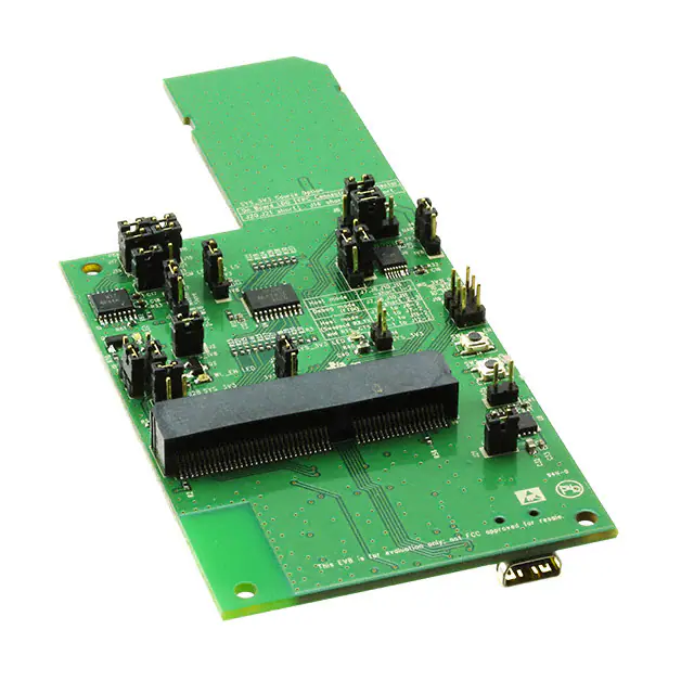
This board is designed for simple connection between the edge 100-pin edge connector COM (WiLink
chip on module) solutions board to the host platforms through an SDIO edge connector for WLAN, a 20pin FPC connector for Bluetooth®, and PCM interfaces or wire cable.
2
Features
•
•
•
3
Ease of connection to multiple host platforms using 1.8-V and 3.3-V interfaces through level shifting.
Evaluation and debugging of the COM8 module through an onboard USB port with four debug
interfaces
Onboard power (through a USB port) and clock, enables distribution to the module
Hardware Description
SDMMC Conn
SYS_3V3
LDO option
PCM_IF
UART_IF
GPIO Conn
SYS_1V8
FPC Conn
BT_EN
WL_EN
WL SW
BT SW
COM8
Conn
SYS_3V3
LDO option
SYS_5V
FTDI
Mini USB Conn
Figure 1. SDMMC Adapter Board Overview
WiLink is a trademark of Texas Instruments.
Bluetooth is a registered trademark of Bluetooth SIG.
2
WL18xxCOM82SDMMC WL18XX SDMMC and UART Adapter Board
Copyright © 2015, Texas Instruments Incorporated
SWRU398 – January 2015
Submit Documentation Feedback
�Hardware Description
www.ti.com
3.1
Connector and Jumper Descriptions
3.1.1
Jumper Settings
Schematics
Reference
Description
Comments
J2
VIO, 1.8-V source
J3
Bluetooth PCM LS (1.8 V/3.3 V)
selection
(1-2) is 1.8 V
(2-3) is 3.3 V (default)
J4
Bluetooth UART LS (1.8 V/3.3
V) selection
(1-2) is 1.8 V
(2-3) is 3.3 V (default)
J24
WLAN SDIO LS (1.8 V/3.3 V)
selection
(1-2) is 1.8 V
(2-3) is 3.3 V (default)
J25
Bluetooth/WL Enable LS (1.8
V/3.3 V) selection
(1-2) is 1.8 V
(2-3) is 3.3 V (default)
J6, J14, J20, J21
3.3-V power selection connect
one of three options
J6 power from SD connector. (default)
J14 power from FPC connector.
J20 power from onboard LDO
J21 must be closed to supply the LDO from USB.
3.1.2
3.1.3
J7, J8, J10, J11
Bluetooth HCI source selection
Host mode: J7, J8, J10, J11 (1-2). (default)
Debug mode: J7, J8, J10, J11 (2-3)
Host mode (swapped): J7-1 to J8-2 / J8-1 to J7-2 / J10-1 to J11-2 /
J11-1 to J12-2
J9
Bluetooth enable control
(1-2): EN control by push-button.
(2-3): Control by host. (default)
J12
WL enable control
(1-2): EN control by push-button.
(2-3): Control by host. (default)
J15, J16, J17, J18
PCM Interface
Option to drive the PCM interface from host through FPC connector or
connect usign the external blue wire cable.
J23
Slow clock
Supply slow clock to the module. (NU by default)
J19
Debug header
Option for WL_IRQ and GPIO9 through GPIO12 to connect using the
external blue wire cable.
Reference
Usage
Comments
SW1
BT_EN
Module Bluetooth enable control
SW2
WL_EN
Module WLAN enable control
Push-Buttons
LEDs
Reference
Color
Description
Comments
LED1
Red
SYS_1V8
ON, when SYS_1V8 is
available
LED2
Red
SYS_3V3
ON, when 3V3 supply is
available
LED3
Blue
BT_EN
ON, when BT_EN is supplied
from host/on board
LED4
Green
WL_EN
ON, when WLAN_EN is
supplied from host/on board
SWRU398 – January 2015
Submit Documentation Feedback
WL18xxCOM82SDMMC WL18XX SDMMC and UART Adapter Board
Copyright © 2015, Texas Instruments Incorporated
3
�Hardware Description
www.ti.com
Figure 2.
3.2
Power Supply
The board is designed to accept power from the SD/FPC connector of Host platform or onboard LDO
generated from 5 V of the USB connector.
3.2.1
3.3 V From SD Connector
Figure 3. Supply 3V3 from SD Connect (J6 short)
4
WL18xxCOM82SDMMC WL18XX SDMMC and UART Adapter Board
Copyright © 2015, Texas Instruments Incorporated
SWRU398 – January 2015
Submit Documentation Feedback
�Hardware Description
www.ti.com
3.2.2
3.3 V From FPC Connector
Figure 4. Supply 3V3 From FFC Connect (J14 Short)
3.3-V Onboard LDO Supply
USB
3.2.3
Figure 5. Supply 3V3 From Onboard LDO (J20, J21 Short)
3.3
Slow Clock Source
There is an option on board to supply the slow clock of 32.768 kHz to the module. By default, this option is
not used because the COM board has an onboard oscillator.
Figure 6. Slow Clock (J23 Short)
SWRU398 – January 2015
Submit Documentation Feedback
WL18xxCOM82SDMMC WL18XX SDMMC and UART Adapter Board
Copyright © 2015, Texas Instruments Incorporated
5
�Hardware Description
3.4
www.ti.com
Debug
An onboard FTDI chip on the adapter board drives all the debug interfaces on one mini USB port.
The FTDI chip provides the ability to have Bluetooth/WiFi firmware logger and Bluetooth HCI/WLAN RS232 control interfaces routed easily to a single USB port that can supply the entire system.
The board can be operated with debug capabilities in two ways:
1. Use the board as a stand-alone COM board debug.
(a) Generate the 3.3 V/1.8 V from the onboard LDO through the USB port J22 (J2, J21, and J20
assembled).
(b) Enable lines can be controlled from the board (Bluetooth J9 pins 1-2 short; WLAN J12 pins 1-2
short).
(c) If the COM8 board does not have onboard slow clock, drive the slow clock to the module (J23).
(d) All four interfaces are driven to the FTDI device and through the USB port. Four virtual ports will be
created on the PC in the following order: Bluetooth UART, Bluetooth logger, WLAN RS232, WLAN
logger (UART J7, J8, J10, J11 short 2-3; Debug LS: J28 assembled)
2. Use the firmware loggers to monitor the operation of the device while running with a host.
(a) Make sure that only one source is driving the SYS_3V3 (J6 or J14) and J20 is disconnected.
(b) For the logger operation, connect the USB cable to J22 and make sure J21 and J28 are
assembled.
(c) On the virtual ports of the PC, Bluetooth logger will be identified as second port and WLAN as the
fourth.
4
Connecting Application
The WL18xxCOM82SDMMC board is designed to connect the WiLink™ 8 evaluation board
(WL18xxMODCOM8x) or any other COM (connectivity on module) board using MEC6 edge 100-pin
connector to any host platform using SD card/FPC connector/single-wire ribbon.
6
WL18xxCOM82SDMMC WL18XX SDMMC and UART Adapter Board
Copyright © 2015, Texas Instruments Incorporated
SWRU398 – January 2015
Submit Documentation Feedback
�Connecting Application
www.ti.com
WL18xxCOM82SDMMC
Adapter Board
WiLink8 Module Evaluation Board
Figure 7. WiLink8 COM8 Board With Adapter Board Overview
SWRU398 – January 2015
Submit Documentation Feedback
WL18xxCOM82SDMMC WL18XX SDMMC and UART Adapter Board
Copyright © 2015, Texas Instruments Incorporated
7
�Connecting Application
4.1
Connecting to Platform
General Connection Options
To Platform SD
Connector
4.1.1
www.ti.com
Figure 8. Connect to Platform With SDMMC for SDIO Interface
20cm
To FPC Connector of
the HOST Platform
Figure 9. Connect to Platform With FPC Cable
8
WL18xxCOM82SDMMC WL18XX SDMMC and UART Adapter Board
Copyright © 2015, Texas Instruments Incorporated
SWRU398 – January 2015
Submit Documentation Feedback
�Connecting Application
www.ti.com
4.1.1.1
Example of Connection Procedure Using the Wire-up Kit
Figure 10 shows an example of the connection procedure using the wire-up kit.
Figure 10. General Wire-up Connection
SWRU398 – January 2015
Submit Documentation Feedback
WL18xxCOM82SDMMC WL18XX SDMMC and UART Adapter Board
Copyright © 2015, Texas Instruments Incorporated
9
�Connecting Application
4.1.2
Freescale Sabre Board Connectivity
COM8 100-pin
WL8 Naming
Adapter Board FPC(J13)
Sabre Board FPC(J13) (1)
66
HCI_TX
3
J13.18 (SPINOR_MISO)
68
HCI_RX
5
J13.16 (SPINOR_CS0)
70
HCI_CTS
4
J13.17 (KEY_ROW4)
72
HCI_RTS
2
J13.19 (KEY_COL4)
89
BT_EN
15
J13.6 (KEY_ROW6)
34
WL_IRQ
19
J13.2 (SPINOR_CLK)
4
WL_EN
20
J13.1 (SPINOR_MOSI)
5,7
3.3V
6,7
J13.14 and J13.15
52
BT_AUD_CLK
10
54
BT_AUD_FSYNC
9
56
BT_AUD_IN
11
58
BT_AUD_OUT
12
SDIO0-3, SDIO_Clk,
SDIO_CMD, Power
J5
WiFi_IF
(1)
(2)
10
www.ti.com
(2)
J500
For Sabre board operation, ensure that R212, R213, R209, R214, R210, R215, R211 are assembled
WiFi SDIO interface is connected directly from J5 connector on adapter board to J500 SD slot on Sabre board
WL18xxCOM82SDMMC WL18XX SDMMC and UART Adapter Board
Copyright © 2015, Texas Instruments Incorporated
SWRU398 – January 2015
Submit Documentation Feedback
�Connecting Application
www.ti.com
Figure 11. Connection Diagram (Top)
SWRU398 – January 2015
Submit Documentation Feedback
WL18xxCOM82SDMMC WL18XX SDMMC and UART Adapter Board
Copyright © 2015, Texas Instruments Incorporated
11
�Revision History
www.ti.com
Figure 12. Connection Diagram (Bottom)
5
12
Revision History
Date
Revision
Details
January 2015
*
Initial Release
WL18xxCOM82SDMMC WL18XX SDMMC and UART Adapter Board
Copyright © 2015, Texas Instruments Incorporated
SWRU398 – January 2015
Submit Documentation Feedback
�IMPORTANT NOTICE
Texas Instruments Incorporated and its subsidiaries (TI) reserve the right to make corrections, enhancements, improvements and other
changes to its semiconductor products and services per JESD46, latest issue, and to discontinue any product or service per JESD48, latest
issue. Buyers should obtain the latest relevant information before placing orders and should verify that such information is current and
complete. All semiconductor products (also referred to herein as “components”) are sold subject to TI’s terms and conditions of sale
supplied at the time of order acknowledgment.
TI warrants performance of its components to the specifications applicable at the time of sale, in accordance with the warranty in TI’s terms
and conditions of sale of semiconductor products. Testing and other quality control techniques are used to the extent TI deems necessary
to support this warranty. Except where mandated by applicable law, testing of all parameters of each component is not necessarily
performed.
TI assumes no liability for applications assistance or the design of Buyers’ products. Buyers are responsible for their products and
applications using TI components. To minimize the risks associated with Buyers’ products and applications, Buyers should provide
adequate design and operating safeguards.
TI does not warrant or represent that any license, either express or implied, is granted under any patent right, copyright, mask work right, or
other intellectual property right relating to any combination, machine, or process in which TI components or services are used. Information
published by TI regarding third-party products or services does not constitute a license to use such products or services or a warranty or
endorsement thereof. Use of such information may require a license from a third party under the patents or other intellectual property of the
third party, or a license from TI under the patents or other intellectual property of TI.
Reproduction of significant portions of TI information in TI data books or data sheets is permissible only if reproduction is without alteration
and is accompanied by all associated warranties, conditions, limitations, and notices. TI is not responsible or liable for such altered
documentation. Information of third parties may be subject to additional restrictions.
Resale of TI components or services with statements different from or beyond the parameters stated by TI for that component or service
voids all express and any implied warranties for the associated TI component or service and is an unfair and deceptive business practice.
TI is not responsible or liable for any such statements.
Buyer acknowledges and agrees that it is solely responsible for compliance with all legal, regulatory and safety-related requirements
concerning its products, and any use of TI components in its applications, notwithstanding any applications-related information or support
that may be provided by TI. Buyer represents and agrees that it has all the necessary expertise to create and implement safeguards which
anticipate dangerous consequences of failures, monitor failures and their consequences, lessen the likelihood of failures that might cause
harm and take appropriate remedial actions. Buyer will fully indemnify TI and its representatives against any damages arising out of the use
of any TI components in safety-critical applications.
In some cases, TI components may be promoted specifically to facilitate safety-related applications. With such components, TI’s goal is to
help enable customers to design and create their own end-product solutions that meet applicable functional safety standards and
requirements. Nonetheless, such components are subject to these terms.
No TI components are authorized for use in FDA Class III (or similar life-critical medical equipment) unless authorized officers of the parties
have executed a special agreement specifically governing such use.
Only those TI components which TI has specifically designated as military grade or “enhanced plastic” are designed and intended for use in
military/aerospace applications or environments. Buyer acknowledges and agrees that any military or aerospace use of TI components
which have not been so designated is solely at the Buyer's risk, and that Buyer is solely responsible for compliance with all legal and
regulatory requirements in connection with such use.
TI has specifically designated certain components as meeting ISO/TS16949 requirements, mainly for automotive use. In any case of use of
non-designated products, TI will not be responsible for any failure to meet ISO/TS16949.
Products
Applications
Audio
www.ti.com/audio
Automotive and Transportation
www.ti.com/automotive
Amplifiers
amplifier.ti.com
Communications and Telecom
www.ti.com/communications
Data Converters
dataconverter.ti.com
Computers and Peripherals
www.ti.com/computers
DLP® Products
www.dlp.com
Consumer Electronics
www.ti.com/consumer-apps
DSP
dsp.ti.com
Energy and Lighting
www.ti.com/energy
Clocks and Timers
www.ti.com/clocks
Industrial
www.ti.com/industrial
Interface
interface.ti.com
Medical
www.ti.com/medical
Logic
logic.ti.com
Security
www.ti.com/security
Power Mgmt
power.ti.com
Space, Avionics and Defense
www.ti.com/space-avionics-defense
Microcontrollers
microcontroller.ti.com
Video and Imaging
www.ti.com/video
RFID
www.ti-rfid.com
OMAP Applications Processors
www.ti.com/omap
TI E2E Community
e2e.ti.com
Wireless Connectivity
www.ti.com/wirelessconnectivity
Mailing Address: Texas Instruments, Post Office Box 655303, Dallas, Texas 75265
Copyright © 2015, Texas Instruments Incorporated
�


 工商网监
湘ICP备2023018690号
工商网监
湘ICP备2023018690号