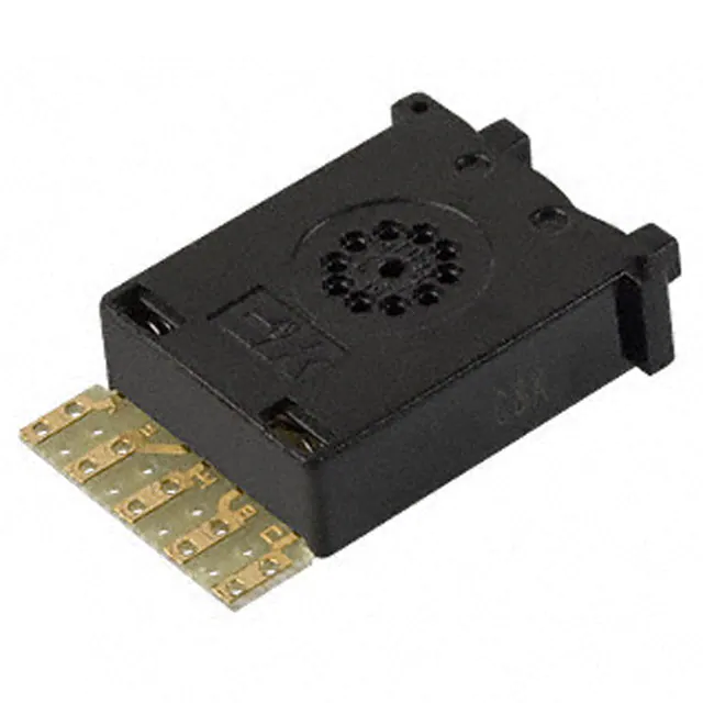
3P Series Miniature Pushwheel Switches
Features/Benefits • Snap-in front mount design for
easy assembly
• 10 position models available
Typical Applications • Test & measurement equipment • Industrial machinery • Computer peripherals
Specifications
CONTACT RATING: CARRY: 1 AMP continuous. SWITCH: 0.4 VA max., 100 mA max., 28 V DC max. OPERATING VOLTAGE: 50 mV to 28 V DC. ELECTRICAL LIFE: 100,000 actuations. CONTACT RESISTANCE: Below 300 m Ω typ. @ 2-4 V DC, 100 mA. INSULATION RESISTANCE: 109 Ω min. (dry). DIELECTRIC STRENGTH: 500 Vrms min. @ sea level between common terminal and any output. OPERATING TEMPERATURE: –10ºC to 65ºC.
Materials
HOUSING: Polycarbonate (UL 94V-0). PUSHWHEEL: Polycarbonate (UL 94V-0). PUSHBUTTON: Polycarbonate (UL 94V-0). ROTOR CONTACTS: Gold over nickel over copper alloy. STATOR CONTACTS: Hard gold over nickel over copper on epoxy fiberglass.
NOTE: Specifications and materials listed above are for switches with standard options. For information on specific and custom switches, consult Customer Service Center.
Note: All models listed are RoHS compliant. See Technical Data section of this catalog for RoHS compliant and compatible definitions and specifications.
Build-A-Switch
To order, simply select desired option from each category and place in the appropriate box. Available options are shown and described on pages M-12 thru M-15. For additional options not shown in catalog, consult Customer Service Center. Consult factory for illumination availability.
Thumbwheel & Pushwheel
Series 3P Miniature pushwheel Number of Sections 0 Switch section 1 1 Switch section 2 2 Switch sections 3 3 Switch sections 4 4 Switch sections
Function Code 21 BCD 1-2-4-8 23 Complement of BCD 1-2-4-8 Mounting Style 0 Snap-in, front mount 3 Snap-in, front mount Terminations 0 Short PCB 1 Extended PCB N Short PCB with solder pins* (.100” spacing) P Extended PCB with solder pins* (.200” spacing) 9 Any combination Color/Marking/Stops 0 Matte black housing, gloss black wheel, white marking, black pushbutton
* Note: Termination option N (RoHS compliant) replaced termination option 3 (Non-RoHS compliant). Termination option P (RoHS compliant) replaced termination option A (Non-RoHS compliant).
M
Dust Lens 0 No Iens 2 Dust lens
Dimensions are shown: Inches (mm) Specifications and dimensions subject to change
M–11
www.ck-components.com
�3P Series Miniature Pushwheel Switches
SERIES
3P
MINIATURE PUSHWHEEL SWITCH
N = Number of sections.
NUMBER OF SECTIONS
0 1-4
Switch section only, no endplates. Number of switch sections in assembly, includes endplates.
Thumbwheel & Pushwheel
NOTE: Endplates and blank sections available separately, see page M-14.
FUNCTION CODE
21
BCD 1-2-4-8, 10 POSITION
23
COMPLEMENT OF BCD 1-2-4-8, 10 POSITION
M
Available Terminations: P, 0, 1, N See figs. 2 & 3, page N-19.
Available Terminations: 0, 1, N See figs. 2 & 3, page N-19.
NOTE: For terminal location diagrams, see page M-14.
Dimensions are shown: Inches (mm) Specifications and dimensions subject to change
M–12
www.ck-components.com
�3P Series Miniature Pushwheel Switches
MOUNTING STYLE
0
SNAP-IN FRONT MOUNT, SECTION PITCH: .300 (7,62) EACH SECTION
N = Number of sections.
Recommended panel thickness: .039-.156 (0,99-3,95)
3
SNAP-IN FRONT MOUNT WITH SPACER, SECTION PITCH: .400 (70,16) EACH SECTION, LAST SECTION .300 (7,62)
N = Number of sections.
Recommended panel thickness: .039-.156 (0,99-3,95)
Thumbwheel & Pushwheel
TERMINATIONS
0
SHORT PCB
1
EXTENDED PCB WITH PROVISION FOR COMPONENTS
N
SHORT PCB, TYPE 0 WITH SOLDER PINS
Signal traces cut, except for common(s).
For terminal location numbers, see next page.
P
EXTENDED PCB, TYPE 1 WITH SOLDER PINS
9
ANY COMBINATION OF TERMINATION CONFIGURATIONS OR SPECIAL TERMINATIONS Specify on configuration form, page M-15 and consult Customer Service Center.
M
For terminal location numbers, see next page. Signal traces cut, except for common(s).
** Note: Termination option N (RoHS compliant) replaced termination option 3 (Non-RoHS compliant). Termination option P (RoHS compliant) replaced termination option A (Non-RoHS compliant). PC Board 1/32" (0,79) thick. NOTE: All terminal holes shown may not be present for all function codes, consult Customer Service Center.
Dimensions are shown: Inches (mm) Specifications and dimensions subject to change
M–13
www.ck-components.com
�3P Series Miniature Pushwheel Switches
TERMINATIONS
Terminal Location Numbers
Solder Pins
Fig. 2
Fig. 1
COLOR/MARKING/STOPS
0
MATTE BLACK HOUSING (Gloss black wheel with white characters, black pushbuttons, no stops.)
DUST LENS
0 2
NO LENS DUST LENS (Protects character face of the wheel from abrasion and dust.)
Thumbwheel & Pushwheel
AVAILABLE HARDWARE
Blank sections, .300 THK. End plates Spacers, .100 THK. (Makes section pitch .400)
LEFT-with hole
RIGHT-with pin
PART NO.
623502000
PART NO.
LEFT-BLACK One left and one right piece required for complee assembly. PART NO.
663702000
BLACK
623602000
RIGHT-BLACK
663602000
BLACK
M
Stop pins
PART NO.
657800000
Dimensions are shown: Inches (mm) Specifications and dimensions subject to change
M–14
www.ck-components.com
�3P Series Miniature Pushwheel Switches
GRAY SHADED AREAS TO BE FILLED IN BY CUSTOMER SERVICE. CATALOG PART NO.
Configuration Form
C&K PART NUMBER
3P
C&K PART NUMBER
COMPANY NAME ADDRESS CUSTOMER CONTACT ORIGINATED BY TEL.# DATE SALES REP.
CUSTOMER PRINT REVISION: DETAILS:
PUSHWHEEL SECTIONS
NO. OF SEC.
FUNCTION CODE – TERMINATIONS – COLOR/MARKING/STOPS/SEAL – ILLUMINATION
ENTER OPTION CODES IN APPROPRIATE BOXES. FUNCTION CODES INCLUDE BLANK SECTIONS (SEE PAGE M-17).
DESCRIBE IN APPROPRIATE ROW
1 2 3 4 5 6 7 8 9 10 11
3P– 3P– 3P– 3P– 3P– 3P– 3P– 3P– 3P– 3P– 3P–
– – – –
Thumbwheel & Pushwheel
– – – – – – – PRODUCTION APPROVAL DATE
QUALITY CONTROL INSTRUCTIONS
Q.C. APPROVAL
DATE
REV.
INITIALS
DATE
M
FOR SWITCHES WITH MORE THAN 11 SECTIONS, CONTINUE ON ADDITIONAL SHEETS.
SPECIAL INSTRUCTIONS OR SPECIFICATIONS:
SHEET _____ OF _____
Dimensions are shown: Inches (mm) Specifications and dimensions subject to change
M–15
www.ck-components.com
�


 工商网监
湘ICP备2023018690号
工商网监
湘ICP备2023018690号
