CMX683
CML Microcircuits
Call Progress and
"Voice" Detector
COMMUNICATION SEMICONDUCTORS
D/683/2 May 2006
Provisional Issue
Features
Applications
•
Detects Single and Dual Call Progress Tones
•
Worldwide Payphone Systems
•
Worldwide Call Progress Tone Compatibility
•
Telephone Redialling Systems
•
"Voice" Detect Outputs (Fast and Slow)
•
Dialling Modems
•
Wide Dynamic Range with Low Falsing
•
Banking and Billing Systems
•
Low Power Operation: 600µA at 3.0V typ.
•
Telecom Test Equipment
•
3.58MHz Xtal/Clock Oscillator
•
Telecom Security Systems
1.
Brief Description
The CMX683 is a general purpose Call Progress tone detector for use in monitoring the progress of calls
in Public Switched Telephone System (PSTN) applications. Dial Tone, Ringing, Busy and Not Available
states can be distinguished by using the host µC to qualify the cadence of the CP DETECT output. The
CMX683 uses advanced digital techniques to characterise valid Call Progress tones, unwanted tones, line
noise and voice or music signals. In contrast to Call Progress detection devices based on simple filtering
techniques, the CMX683 offers excellent sensitivity coupled with low false detection rates.
The response time of the CMX683 allows it to operate with almost any Call Progress system. In particular
the ‘stuttered dial tone’ of voice mail messaging systems is supported. The use of statistical processing
techniques, which analyse signal frequency, duration and amplitude, enable the CMX683 to distinguish
voice or music activity from DTMF or Call Progress signals. Separate outputs integrate the "voice" activity
over both shorter and longer periods, enabling payphone and other billing systems to commence charging
when a line connection has been established. A single 3.58MHz crystal ensures accurate and repeatable
performance. With supply requirements between 2.7V and 5.5V and a low current consumption, the
CMX683 can be easily integrated into a wide range of telecom equipments. The CMX683 has a similar
pinout to all commonly used Call Progress detectors and is available in DIP, TSSOP or SOIC packages.
© 2006 CML Microsystems Plc
�Call Progress and "Voice" Detector
CMX683
CONTENTS
Page
Section
1.
Brief Description ..................................................................................... 1
2.
Block Diagram ......................................................................................... 3
3.
Signal List ................................................................................................ 4
4.
External Components............................................................................. 5
5.
General Description................................................................................ 6
5.1
Overall Function Description.................................................... 6
5.2
Glossary...................................................................................... 6
5.3
Block Diagram Description ....................................................... 7
5.4
Decode Output Truth Table ...................................................... 7
6.
Application Notes ................................................................................... 9
7.
Performance Specification................................................................... 11
7.1
Electrical Performance ............................................................ 11
7.2
Packaging ................................................................................. 14
© 2006 CML Microsystems Plc
2
D/683/2
�Call Progress and "Voice" Detector
2.
CMX683
Block Diagram
Figure 1 Block Diagram
© 2006 CML Microsystems Plc
3
D/683/2
�Call Progress and "Voice" Detector
3.
CMX683
Signal List
SOIC
Package
TSSOP
Package
DIP
Package
D4
Pin No.
1
E4
Pin No.
1
P1
Pin No.
Signal
Name
2
2
1
3
3
4
Type
Description
NC
Reserved for future use. Do not make any
connection to this pin.
XTAL
I/P
The input to the on-chip oscillator, to be used
in conjunction with the XTALN output. An
external crystal only is required. All other
components are on-chip. If the on-chip
oscillator is not used, this pin should be
connected to VSS.
CLOCK IN
I/P
The external clock input. Connect the
CONFIG pin to VDD to enable this input.
4
2
XTALN
O/P
The inverted output of the on-chip oscillator.
Leave unconnected if not used.
5
5
3
ENABLE
I/P
A logic 1 applied to this input enables all
detector outputs. A logic 0 will force all
detector outputs to a logic 0.
6
6
VOICE
SLOW
O/P
When a Non Call Progress signal is detected
this output goes to a logic 1. (See Table 1).
7
7
4
CP
DETECT
O/P
When a Call Progress signal is detected this
output goes to a logic 1. (See Table 1).
8
8
NC
Reserved for future use. Do not make any
connection to this pin.
9
9
NC
Reserved for future use. Do not make any
connection to this pin.
10
10
5
I/P
Signal input (which should be ac coupled as
the dc bias on this pin is set internally).
11
11
NC
Reserved for future use. Do not make any
connection to this pin.
12
12
6
VSS
Power
13
13
7
VOICE
FAST
O/P
When a Non Call Progress signal is detected
this output goes to a logic 1. (See Table 1).
14
14
VREF
O/P
Internally generated reference voltage held at
½VDD and available to power external circuits.
15
15
8
VDD
Power
16
16
CONFIG
I/P
Notes:
I/P = Input
© 2006 CML Microsystems Plc
SIGIN
O/P = Output
4
The negative supply rail (ground).
The positive supply rail. This pin should be
decoupled to VSS by a capacitor.
Oscillator configuration. Leave unconnected
when using an external crystal. This pin has
an internal pulldown to the VSS pin.
NC = No Connection
D/683/2
�Call Progress and "Voice" Detector
4.
CMX683
External Components
Typical Values:
C1
C2
X1
0.1µF ± 20%
0.1µF ± 20%
3.579545MHz (refer to Section 7.1)
Note:
C1 is not required if the input is referenced to VREF.
Figure 2 Recommended External Components
To achieve good noise performance, VDD decoupling and protection of the receive path from extraneous
in-band signals are very important. It is recommended that the printed circuit board is laid out with a
ground plane in the CMX683 area to provide a low impedance connection between the VSS pin and the
VDD decoupling capacitor.
© 2006 CML Microsystems Plc
5
D/683/2
�Call Progress and "Voice" Detector
5.
General Description
5.1
Overall Function Description
CMX683
The CMX683 Call Progress Tone Detector uses different tone detection methods from those
commonly found with other products.
Many traditional devices from other suppliers use a bandpass filter followed by an energy
detector. The filter is usually designed to pass input signals with a frequency between about 300
and 700 Hz, and the amplitudes of signals in this range are then checked against a level
threshold. Any signal of acceptable level in this frequency band is classed as a Call Progress
tone, including signals due to speech, music, DTMF and noise. False outputs are a common
feature with these products. To avoid background noise causing a stuck “detect” output, the
sensitivity of such devices is often poor.
The CMX683, by contrast, uses a stochastic signal processing technique based on analysis in
both the frequency and time domains, with signal amplitude forming part of the decision process.
This analysis includes checks on whether the signal has a profile which matches international
standards for Call Progress tones, or whether the profile is more likely to match that of DTMF,
speech, music, noise or no signal. The frequency response of the CMX683 is confined to the Call
Progress band, plus a small extension above and below this band. This ensures that the
CMX683 will not respond to FAX, Modem or other out-of-band signals.
The following Glossary and the Decode Truth Table in section 5.4 provide a simple explanation of
the decoding functions and features offered by the CMX683.
5.2
Glossary
Call Progress Tones: The single and dual frequency tones in the range 350 to 620 Hz which
are specified widely for call progress signalling.
Call Progress Band: The nominal range 315 to 650 Hz within which the CMX683 will detect Call
Progress tones. The detection algorithm requires that these tones have the characteristics typical
of Call Progress Tones.
No Signal:
The absence of an input signal (below the detection threshold) or
A signal below 190Hz or
A signal between 900Hz and 10kHz.
Non Call Progress ("Voice") Signal:
A signal falling within the nominal range of 190 to 895 Hz,
but NOT within the Call Progress band or
A signal falling within the nominal range of 190 to 895 Hz,
but NOT meeting the Call Progress detection requirements for that part
of the signal which falls within the Call Progress band. Subject to the
duration and other characteristics of such signals, the CMX683 will
usually interpret these as a Non Call Progress signal (ie "Voice" activity).
Note that signals above 10kHz should not exceed -38dB (relative to 775mVrms), to avoid
aliasing.
Nominal: Subject to dynamic tolerances within the signal analysis process. Absolute values are
not material or adverse to performance.
© 2006 CML Microsystems Plc
6
D/683/2
�Call Progress and "Voice" Detector
5.3
CMX683
Block Diagram Description
Amplifier
The input signal is amplified by a self-biased inverting amplifier. The dc bias of this input is
internally set at ½VDD.
Signal Analyser
The frequency range, quality and consistency of the input signal is analysed by this functional
block. To be classified as a Call Progress signal the input signal frequencies must lie between
315 and 650 Hz, and the signal to noise ratio must be 16dB or greater. The signal must have a
minimum rms amplitude of about -60dB (relative to 775mVrms) and the signal must be consistent
over a period of about 80ms. These decode criteria are continuously monitored and the
assessment is updated every 6ms. To be classified as a Non Call Progress ("Voice") signal the
input signal frequencies must lie between 190 and 895 Hz and the frequencies must not match
the predefined profiles for DTMF or Call Progress signals. The signal must have a minimum rms
amplitude of about -60dB (relative to 775mVrms) and the signal must show activity over a period
of about 145ms (fast response) or 500ms (slow response).
Control and Output Logic
This block categorises the nature of the signal into Call Progress and Non Call Progress output
states. A Non Call Progress output is further checked for activity over a longer detection period,
resulting in a VOICE FAST output responding to speech/music in around 90ms and a VOICE
SLOW output (with a more consistent detection) responding in around 370ms. If the VOICE
FAST output is at logic 1 for more than 51% of the previous 728ms then the VOICE SLOW output
will change to a logic 1. If the VOICE FAST output is at logic 1 for less than 10% of the previous
728ms then the VOICE SLOW output will change to a logic 0. The Decode Output Truth Table on
the following page gives further details. Also refer to the timing diagram in Figure 5.
Level Detector
The Level Detector operates by measuring the level of the amplified input signal and comparing it
with a preset threshold, which has a nominal value of -42dB (relative to 775mVrms). The Level
Detector output goes to the Control and Output Logic block, where the Call Progress signal and
Voice detector outputs are gated with the Level Detector output. The CP DETECT, VOICE FAST
and VOICE SLOW outputs are valid only if the input signal level is above this preset threshold.
Xtal Oscillator
If the on-chip Xtal oscillator is to be used, an external 3.58MHz crystal (X1) only is required and
the CONFIG pin should be left unconnected. If an external clock source is to be used, the clock
should be connected to the CLOCK IN input pin and the XTAL pin should be connected to VSS.
The XTALN pin should be left unconnected and the CONFIG pin must be connected to VDD.
Note that this external clock option is not available with the P1 package.
Enable Input
A logic 1 applied to this input enables the whole device, including the outputs and the xtal
oscillator circuit. About 15ms should be allowed for the oscillator to start up, once enabled.
A logic 0 applied to this input resets the device, then powersaves the xtal oscillator, the signal
analyser, level detector and control and output logic. In addition the CPDETECT, VOICE FAST
and VOICE SLOW outputs will be cleared to a logic 0. The VREF supply is maintained at ½VDD, so
will continue to draw a small amount of current.
5.4
Decode Output Truth Table
In the following Truth Table it should be noted that it is possible to get both CP DETECT and
VOICE FAST or VOICE SLOW outputs simultaneously at logic 1. If the activity is initially
© 2006 CML Microsystems Plc
7
D/683/2
�Call Progress and "Voice" Detector
CMX683
consistent with and meets the Call Progress signal profile, the CP DETECT output will go to logic
1. If the activity subsequently meets the Non Call Progress signal profile, the VOICE FAST output
(and, eventually, the VOICE SLOW output) will go to a logic 1 without changing the CP DETECT
output. The host µC must then use cadence information to decide what signal is present. See
section 6.
Note that CP DETECT responds to the whole range of Call Progress tones from 315 to 650 Hz.
CONDITIONS
CP DETECT
"VOICE"
FAST/SLOW
No Signal
Call Progress Signal:
Will detect 350+440, 400+450, 440+480, 400,
425, 440, 450, 480+620, 600 and 620Hz tones
DTMF Signal
Non Call Progress Signal (eg voice)
FAX/Modem or other out-of-band signals
0
1
0
0
0
0
0
0
1
0
Table 1 Decode Output Truth Table
© 2006 CML Microsystems Plc
8
D/683/2
�Call Progress and "Voice" Detector
6.
CMX683
Application Notes
On power-up, it will take no more than 15ms to initialise the internal state. This delay should be
accounted for before the CP DETECT, VOICE SLOW and VOICE FAST outputs are valid.
Figure 3 A typical Telephone Line Circuit Application
R1 470kΩ
R2 470kΩ
R3 470kΩ
Note:
R4 470kΩ
R5 100kΩ
R6 100kΩ
C2
C3
C4
C5
0.1µF
0.01µF 250V
0.01µF 250V
0.1µF
1. Resistors ±1%, Capacitors ±20%, unless otherwise stated.
2. A low offset opamp is needed. The decoupling capacitor C1 (see Figure 2) is not required if
the quiescent dc level at the opamp output is the same as VREF.
All outputs should be examined for cadence information. Sometimes a call progress signal will
not cause the CPDETECT output to go to a 1 because the signal has a high harmonic content, or
is amplitude or frequency modulated by another tone. Often this will result in a “voice” detection
instead, so it is good practice to examine the VOICE FAST output for a regular call progress
cadence. A typical detection strategy might be:
To detect Call Progress tones
Examine CPDETECT cadence first, then examine VOICE FAST cadence. Ignore any output
which has an unexpected cadence. A more accurate result will be obtained by checking the
cadence over a long period of time.
To detect “Voice” activity
Examine the VOICE FAST cadence first. If this is irregular, it probably signifies “voice” activity.
This can be confirmed by examining the VOICE SLOW output, which integrates the “voice”
detection over a much longer period. If this output goes to a 1 and stays at a 1 for a long period
of time, it has almost certainly detected “voice” activity.
© 2006 CML Microsystems Plc
9
D/683/2
�Call Progress and "Voice" Detector
CMX683
The detection process for both “voice” and call progress tones depends on stochastic signal
processing techniques and requires the customer to examine the cadence (timing) information
before a final decision can be made. Frequently the call progress tone will contain noise, which
may cause the CMX683 to respond with a VOICE FAST output instead. An example of this is
shown in Figure 4, where the VOICE FAST output is maintained until the call progress tone has
ceased, as illustrated by time L2.
Figure 4: CMX 683 Voice / Tone Response
© 2006 CML Microsystems Plc
10
D/683/2
�Call Progress and "Voice" Detector
7.
Performance Specification
7.1
Electrical Performance
CMX683
7.1.1 Absolute Maximum Ratings
Exceeding these maximum ratings can result in damage to the device.
Min.
-0.3
-0.3
-30
-20
Max.
7.0
VDD + 0.3
+30
+20
Units
V
V
mA
mA
P1 Package
Total Allowable Power Dissipation at Tamb = 25°C
... Derating
Storage Temperature
Operating Temperature
Min.
Max.
800
13.0
+125
+85
Units
mW
mW/°C
°C
°C
E4 Package
Total Allowable Power Dissipation at Tamb = 25°C
... Derating
Storage Temperature
Operating Temperature
Min.
Max.
300
5.0
+125
+85
Units
mW
mW/°C
°C
°C
D4 Package
Total Allowable Power Dissipation at Tamb = 25°C
... Derating
Storage Temperature
Operating Temperature
Min.
Max.
800
13.0
+125
+85
Units
mW
mW/°C
°C
°C
Max.
5.5
3.59
Units
V
MHz
Supply (VDD - VSS)
Voltage on any pin to VSS
Current into or out of VDD and VSS pins
Current into or out of any other pin
-55
-40
-55
-40
-55
-40
Operating Limits
Correct operation of the device outside these limits is not implied.
Notes
Supply (VDD - VSS)
Xtal Frequency
© 2006 CML Microsystems Plc
11
Min.
2.7
3.57
D/683/2
�Call Progress and "Voice" Detector
7.1.3
CMX683
Operating Characteristics
Xtal Frequency = 3.579545MHz, S/N = 16dB, Noise Bandwidth = 5kHz,
VDD = 3.0V to 5.0V, Tamb = -40°C to +85°C. 0dB = 775mVrms.
Notes
Min.
Typ.
Max.
Units
1
1
1
8
–
–
–
45%
250
1.0
0.6
50%
–
1.5
1.0
55%
µA
mA
mA
VDD
2
–
–
40.0
16.0
0.1
-38.0
–
–
–
–
–
–
MΩ
dB
dB
Clock Input
‘High’ Pulse Width
‘Low’ Pulse Width
Gain (I/P = 1mVrms at 100Hz)
3
3
100
100
20.0
–
–
–
–
–
–
ns
ns
dB
Level Detector
Must Detect Signal Level
Must Not Detect Signal Level
4
4
-38.0
–
–
–
–
-50.0
dB
dB
315
750
–
–
650
250
Hz
Hz
5
5
5
5
6
80%
–
-5.0
–
90%
–
–
–
7.5
–
–
20%
+5.0
–
–
VDD
VDD
µA
pF
VDD
6
–
–
10%
VDD
DC Parameters
IDD (ENABLE = 0)
IDD (ENABLE = 1)
IDD (ENABLE = 1)
VREF Output
(VDD = 5.0V)
(VDD = 5.0V)
(VDD = 3.0V)
AC Parameters
SIGIN pin
Input Impedance
Minimum Input Signal Level
Input Signal Dynamic Range
Signal to Noise Ratio
7
Call Progress Band
Must Detect Range
Must Not Detect Range
Logic Interface
Input Logic 1 Level
Input logic 0 level
Input leakage current (Vin = 0 to VDD)
Input Capacitance
Output logic 1 level (lOH = 120µA)
Output logic 0 level (lOL = 360µA)
Notes:
1.
2.
3.
4.
5.
6.
7.
Not including any current drawn from the CMX683 pins by external circuitry.
Small signal impedance over the frequency range 100Hz to 2000Hz and at VDD = 5.0V.
Timing for an external input to the CLOCK IN pin.
Input signal level at VDD = 5.0V, scale signal for different VDD.
ENABLE and CONFIG pins.
CP DETECT, VOICE FAST and VOICE SLOW pins.
Nominal values which are subject to dynamic tolerances within the signal analysis process,
as a result of using stochastic signal processing techniques.
8. Load impedance on this output must exceed 330kΩ.
© 2006 CML Microsystems Plc
12
D/683/2
�Call Progress and "Voice" Detector
CMX683
Electrical Performance (continued)
Figure 5 µC Parallel Interface Timings
For the following conditions unless otherwise specified:
Xtal Frequency = 3.579545MHz, VDD = 3.0V to 5.0V, Tamb = -40°C to +85°C, S/N = 20dB.
Notes
Min.
Typ.
Max.
Units
-
-
40.0
ms
80.0
-
-
ms
Signal Timings (ref. Figure 5)
tl
Burst Length Ignored
tL
Burst Length Detected
tGI
Call Progress Tone Gap Length
Ignored
9
-
-
20.0
ms
tGD
Call Progress Tone Gap Length
Detected
9
40.0
-
-
ms
tRP
Call Progress Tone Response Time
10
-
46
80.0
ms
tDRP
Call Progress Tone De-Response
Time
10
-
46
80.0
ms
Notes:
9.
10.
Only applies to bursts of the same frequency.
Measured with 350 + 440 Hz tone pair.
© 2006 CML Microsystems Plc
13
D/683/2
�Call Progress and "Voice" Detector
7.2
CMX683
Packaging
Figure 6 SOIC Mechanical Outline: Order as part no. CMX683D4
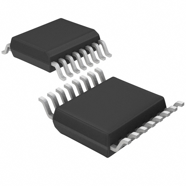
Figure 7 TSSOP Mechanical Outline: Order as part no. CMX683E4
© 2006 CML Microsystems Plc
14
D/683/2
�Call Progress and "Voice" Detector
CMX683
Figure 8 DIP Mechanical Outline: Order as part no. CMX683P1
2006 CML Microsystems Plc
15
D/683/2
�Call Progress and "Voice" Detector
CMX683
Handling precautions: This product includes input protection, however, precautions should be taken to prevent device
damage from electro-static discharge. CML does not assume any responsibility for the use of any circuitry described. No
IPR or circuit patent licences are implied. CML reserves the right at any time without notice to change the said circuitry and
this product specification. CML has a policy of testing every product shipped using calibrated test equipment to ensure
compliance with this product specification. Specific testing of all circuit parameters is not necessarily performed.
www.cmlmicro.com
For FAQs see: www.cmlmicro.com/products/faqs/
For a full data sheet listing see: www.cmlmicro.com/products/datasheets/download.htm
For detailed application notes: www.cmlmicro.com/products/applications/
Oval Park, Langford,
Maldon, Essex,
CM9 6WG - England.
4800 Bethania Station Road,
Winston-Salem,
NC 27105 - USA.
No 2 Kallang Pudding
Road, #09 - 05/06 Mactech
Industrial Building,
Singapore 349307
No. 218, Tian Mu Road
West, Tower 1, Unit 1008,
Shanghai Kerry Everbright
City, Zhabei,
Shanghai 200070,
China.
Tel: +44 (0)1621 875500
Tel: +65 6745 0426
Fax: +44 (0)1621 875600
Tel: +1 336 744 5050,
800 638 5577
Fax: +1 336 744 5054
Fax: +65 6745 2917
Tel: +86 21 6317 4107
+86 21 6317 8916
Fax: +86 21 6317 0243
Sales:
sales@cmlmicro.com
Sales:
us.sales@cmlmicro.com
Sales:
sg.sales@cmlmicro.com
Sales:
cn.sales@cmlmicro.com.cn
Technical Support:
techsupport@cmlmicro.com
Technical Support:
us.techsupport@cmlmicro.com
Technical Support:
sg.techsupport@cmlmicro.com
Technical Support:
sg.techsupport@cmlmicro.com
�