Document 833-1
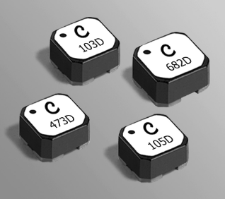
Coupled Inductors LPD6235
For Flyback, SEPIC, Zeta
and other Applications
Tight coupling (k ≥ 0.97) makes the LPD6235 series of
coupled inductors ideal for use in a variety of circuits
including flyback, multi-output buck, SEPIC and Zeta.
These coupled miniature shielded inductors are 3.5 mm
high and 6.0 mm square. They provide high inductance,
high efficiency and excellent current handling in low cost
part.
They can be used as two single inductors connected in
series or parallel, as a common mode choke or as a 1 : 1
transformer.
+
+
D
L1
C
L2
VOUT
C
VIN
–
SW
–
0.236 ±0.003
6,0 ±0,08
+
VOUT
C
AUX
–
4
XXX X
D
L2
Dot indicates pin 1
1
2
Typical Flyback Converter
+
0.236 ±0.003
6,0 ±0,08
+
VIN
3
L1
D
SW
VOUT
C
–
–
Typical Buck Converter with auxiliary output
Dash
number
Internal
code
D
+
0.138
max
3,5
L1
Recommended
Land Pattern
1
4
0.047
1,20
0.167 0.079
4,25 2,00
0.260
6,60
1
C
L2
Q
–
C
+
L2
C1
Q
–
VOUT
–
Typical SEPIC schematic
+
VIN
0.079
2,00
0.167
4,25
0.260
6,60
0.079
2,00
2
45°
typ
3
2
L1
VIN
+
C1
L1
C
D
Typical Zeta schematic
C
VOUT
–
4
Dimensions are in
L2
inches
mm
3
US +1-847-639-6400 sales@coilcraft.com
UK +44-1236-730595 sales@coilcraft-europe.com
Taiwan +886-2-2264 3646 sales@coilcraft.com.tw
China +86-21-6218 8074 sales@coilcraft.com.cn
Singapore + 65-6484 8412 sales@coilcraft.com.sg
Document 833-1 Revised 07/15/13
© Coilcraft Inc. 2014
This product may not be used in medical or high
risk applications without prior Coilcraft approval.
Specification subject to change without notice.
Please check web site for latest information.
�Document 833-2
Coupled Inductors – LPD6235 Series
Part number1
Inductance2
±20% (µH)
LPD6235-682ME_
6.8
LPD6235-103ME_
10
LPD6235-223ME_
22
LPD6235-473ME_
47
LPD6235-474ME_ 470
LPD6235-105ME_ 1000
LPD6235-155ME_ 1500
LPD6235-205ME_ 2000
Isat (A)6 Irms (A)
10% 20% 30% both one
drop drop
drop windings7 winding8
0.108
31
0.99
0.10
2.80 3.00 3.12 1.60 2.26
0.157
27
0.99
0.12
2.50 2.70 2.80 1.40 1.98
0.300
15
>0.99
0.15
1.50
1.67
1.73
0.85 1.20
0.620
9.7
>0.99
0.21
0.90
0.98
0.99
0.60 0.85
3.50 3.0 >0.99 0.61 0.18 0.22 0.23 0.25 0.35
7.00
1.9 >0.99 1.05 0.12 0.14 0.15 0.15 0.21
10.8
1.5 >0.99 1.70 0.12 0.12 0.13 0.14 0.20
16.0
1.3 >0.99 2.10 0.08 0.11 0.12 0.11 0.16
Leakage5
DCR SRF Coupling
typ4
coefficient L typ
(Ohms)
(MHz)
typ
(µH)
max3
1. Please specify termination and packaging codes:
LPD6235-205MEC
Termination: E = RoHS compliant Silver-palladium-platinum-glass frit.
Special order:
T = RoHS tin-silver-copper (95.5/4/0.5) or S = nonRoHS tin-lead (63/37).
Packaging: C = 7″ machine-ready reel. EIA-481 embossed plastic
tape (350 parts per full reel).
B = Less than full reel. In tape, but not machine ready.
To have a leader and trailer added ($25 charge), use
code letter D instead.
D = 13″ machine-ready reel. EIA-481 embossed plastic
tape. Factory order only, not stocked (1500 parts per
full reel).
2. Inductance shown for each winding, measured at 100 kHz, 0.1 Vrms,
0 Adc on an Agilent/HP 4284A LCR meter or equivalent. When leads
are connected in parallel, inductance is the same value. When leads are
connected in series, inductance is four times the value.
3. DCR is for each winding. When leads are connected in parallel, DCR
is half the value. When leads are connected in series, DCR is twice the
value.
4. SRF measured using an Agilent/HP 4191A or equivalent. When leads
are connected in parallel, SRF is the same value.
5. Leakage inductance is for L1 and is measured with L2 shorted.
6. DC current, at which the inductance drops the specified amount from its
value without current. It is the sum of the current flowing in both windings.
7. Equal current when applied to each winding simultaneously that causes
a 40°C temperature rise from 25°C ambient. See temperature rise
calculation.
8. Maximum current when applied to one winding that causes a 40°C
temperature rise from 25°C ambient. See temperature rise calculation.
9. Electrical specifications at 25°C.
Refer to Doc 639 “Selecting Coupled Inductors for SEPIC Applications.”
Refer to Doc 362 “Soldering Surface Mount Components” before soldering.
Coupled Inductor Core and Winding Loss Calculator
This web-based utility allows you to enter frequency, peak-to-peak
(ripple) current, and Irms current to predict temperature rise and overall
losses, including core loss. Go to online calculator.
Core material Ferrite
Core and winding loss Go to online calculator
Weight 420 – 480 mg
Environmental RoHS compliant, halogen free
Terminations RoHS compliant silver-palladium-platinum-glass frit.
Other terminations available at additional cost.
Ambient temperature –40°C to +85°C with Irms current, +85°C to
+125°C with derated current
Storage temperature Component: –40°C to +125°C.
Tape and reel packaging: –40°C to +80°C
Winding to winding isolation 100 V
Resistance to soldering heat Max three 40 second reflows at
+260°C, parts cooled to room temperature between cycles
Moisture Sensitivity Level (MSL) 1 (unlimited floor life at
很抱歉,暂时无法提供与“LPD6235-103MRC”相匹配的价格&库存,您可以联系我们找货
免费人工找货- 国内价格
- 1+11.88280
- 10+11.20378
- 30+9.84575
- 100+8.82722
- 500+8.14820
- 1000+7.67289
- 国内价格
- 1+26.09280
- 10+25.53120
- 30+25.15320
- 国内价格
- 100+32.50800
- 350+25.59600