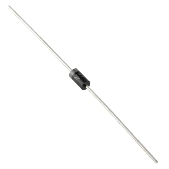
General Purpose Silicon Rectifiers
1N4001-G Thru. 1N4007-G
Voltage: 50 to 1000 V
Current: 1.0 A
RoHS Device
DO-41
Features
- Low cost construction.
- Fast forward voltage drop.
- Low reverse leakage.
- High forward surge current capability.
1.000(25.40) Min.
- High soldering temperature guarantee: 260 OC/10
seconds, 0.375”(9.5mm) lead length at 5lbs(2.3kg)
tension.
0.205(5.21)
0.161(4.10)
Mechanical data
0.117(2.97) DIA.
0.078(2.00) DIA.
- Case: Transfer molded plastic, DO-41
- Epoxy: UL 94V-0 rate flame retardant
1.000(25.40) Min.
- Polarity: Indicated by cathode band
- Lead: Plated axial lead, solderable per
MIL-STD-750, method 2026
0.035(0.90) DIA.
0.027(0.70) DIA.
- Mounting position: Any
- Weight: 0.012ounce, 0.34 grams(approx.).
Dimensions in inches and (millimeter)
Electrical Characteristics (at TA=25°C unless otherwise noted)
Ratings at 25°C ambient temperature unless otherwise specified.
Single phase, half wave, 60Hz, resistive or inductive load.
For capacitive load derate current by 20%.
Symbol
1N4001
-G
1N4002
-G
1N4003
-G
1N 4004
-G
1N4005
-G
1N4006
-G
1N4007
-G
Unit
Maximum Repetitive Peak Reverse Voltage
VRRM
50
100
200
400
600
800
1000
V
Maximum RMS Voltage
VRMS
35
70
140
280
420
560
700
V
Maximum DC Blocking Voltage
VDC
50
100
200
400
600
800
1000
V
Maximum Average Forward Rectified Current
0.375"(9.5mm) Lead Length @TA=55°C
I(AV)
1.0
A
Peak Forward Surge Current,
8.3mS single half sine-wave superimposed on
rated load (JEDEC method)
IFSM
30
A
Maximum Instantaneous Forward Voltage @1.0A
VF
1.1
V
Parameter
Maximum DC Reverse Current at Rated
DC Blocking voltage per element
TA=25°C
5.0
IR
μA
50
TA=100°C
CJ
15
pF
RθJA
60
°C/W
Operating Temperature Range
TJ
-55 ~ +150
°C
Storage Ttemperature Range
TSTG
-55 ~ +150
°C
Typical Junction Capacitance (Note 1)
Typical Thermal Resistance (Note 2)
NOTES:
1. Measured at 1.0MHz and applied reverse voltage of 4.0V DC.
2. Thermal Resistance from junction to ambient and junction to lead at 0.375”(9.5mm) lead length P.C.B mounted.
Company reserves the right to improve product design , functions and reliability without notice.
REV:B
Page 1
QW-BG013
Comchip Technology CO., LTD.
�General Purpose Silicon Rectifiers
Rating and Characteristic Curves ( 1N4001-G Thru. 1N4007-G)
Fig.1 - Typical Forward Current
Derating Curve
Fig.2 - Maximum. Non-Repetitive Peak
Forward Surge Current
35
Peak Forward Surge Current, ΙFSM (A)
Average Forward Current, I(AV) (A)
1.2
1.0
0.8
0.6
0.4
Single phase
Half wave, 60Hz
Resistive or
inductive load
0.2
30
25
20
15
10
5
0
0
0
25
50
75
100
125
150
175
1
2
5
10
20
50
100
Ambient Temperature, TA (°C)
Number of Cycles at 60Hz
Fig.3 - Typical Instantaneous Forward
Characteristics
Fig.4 - Typical Reverse Characteristics
Instantaneous Reverse Current, IR (mA)
10
Instantaneous Forward Current, IF (A)
8.3mS, single half
sine-wave, JEDEC
method.
TJ=TJmax
1.0
0.1
Pulse width=300μs.
1% duty cycle
TJ=25°C
0.01
10
TJ=100 OC
1.0
0.1
TJ=25 OC
0.01
0.6
0.8
1.0
1.2
1.4
1.6
1.8
2.0
0
Instantaneous Forward Voltage, VF (V)
20
40
60
80
100
120
140
Percent of Peak Reverse Voltage, (%)
Fig.5 - Typical Junction Capacitance
100
Capacitance, CJ (pF)
f=1MHz
O
TJ=25 C
10
10
0.1
1
10
100
Reverse Voltage, VR (V)
Company reserves the right to improve product design , functions and reliability without notice.
REV:B
Page 2
QW-BG013
Comchip Technology CO., LTD.
�General Purpose Silicon Rectifiers
Taping Specification For Axial Lead Diodes
E
90°± 5°
Z
A
L1
B
L2
T
E
D0
W0
L
D1
H
D
W
DO-41
SYMBOL
A
B
Z
T
E
|L1-L2|
(mm)
5.00 ± 0.50
52.40 ± 1.50
1.60 (max)
6.00 ± 0.40
3.00 (max)
1.00 (max)
0.197 ± 0.020 2.063 ± 0.059
0.063 (max)
0.236 ± 0.016
0.118 (max)
0.039 (max)
(inch)
DO-41
SYMBOL
D1
D0
D
W0
L
W
H
(mm)
85.70 ± 0.30
16.60 ± 0.40
330.00
72.00 ± 3.00
260.00 ± 5.00
75.00 ± 5.00
150.00 ± 5.00
(inch)
3.374 ± 0.012
0.654 ± 0.016
12.992
2.835 ± 0.118
10.236 ± 0.197 2.953 ± 0.197
5.906 ± 0.197
Company reserves the right to improve product design , functions and reliability without notice.
REV:B
Page 3
QW-BG013
Comchip Technology CO., LTD.
�General Purpose Silicon Rectifiers
Marking Code
Part Number
Marking Code
Packaging
1N4001T-G
1N4002T-G
1N4003T-G
1N4004T-G
1N4005T-G
1N4006T-G
1N4007T-G
1N4001A-G
1N4002A-G
1N4003A-G
1N4004A-G
1N4005A-G
1N4006A-G
1N4007A-G
1N4001B-G
1N4002B-G
1N4003B-G
1N4004B-G
1N4005B-G
1N4006B-G
1N4007B-G
1N4001
1N4002
1N4003
1N4004
1N4005
1N4006
1N4007
1N4001
1N4002
1N4003
1N4004
1N4005
1N4006
1N4007
1N4001
1N4002
1N4003
1N4004
1N4005
1N4006
1N4007
REEL
REEL
REEL
REEL
REEL
REEL
REEL
AMMO
AMMO
AMMO
AMMO
AMMO
AMMO
AMMO
BULK
BULK
BULK
BULK
BULK
BULK
BULK
1N4XXX
1N4XXX = Product type marking code
Note:
1) Suffix code after part number to specify packaging item .
Packaging
REEL PACK
AMMO PACK
BULK PACK
Code
T
A
B
Standard Packaging
BULK PACK
REEL PACK
Case Type
DO-41
REEL
Reel Size
( pcs )
(inch)
5,000
13
Case Type
BOX
( pcs )
DO-41
1,000
AMMO PACK
Case Type
BOX
( pcs )
DO-41
5,000
Company reserves the right to improve product design , functions and reliability without notice.
REV:B
Page 4
QW-BG013
Comchip Technology CO., LTD.
�
很抱歉,暂时无法提供与“1N4007B-G”相匹配的价格&库存,您可以联系我们找货
免费人工找货