SMD Efficient Fast Recovery Rectifier
CEFB201-G Thru CEFB205-G (RoHS Device)
Reverse Voltage: 50 ~ 600 Volts Forward Current: 2.0 Amp Features:
Ideal for surface mount applications Easy pick and place Plastic package has Underwriters Lab. flammability classification 94V-0. Super fast recovery time for high efficient Built-in strain relief Low forward voltage drop
0.185(4.70) 0.160(4.06) 0.012(0.31) 0.006(0.15) 0.096(2.44) 0.083(2.13) 0.083(2.11) 0.075(1.91) 0.155(3.94) 0.130(3.30)
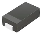
SMB / DO-214AA
Mechanical Data:
Case: JEDEC DO-214AA molded plastic Terminals: solderable per MIL-STD-750, method 2026 Polarity: Color band denotes cathode end Approx. Weight: 0.063 gram
0.050(1.27) 0.030(0.76) 0.220(5.59) 0.200(5.08)
0.008(0.20) 0.203(0.10)
Dimensions in inches and (millimeter)
Maximum Ratings and Electrical Characterics:
Parameter Max. Repetitive Peak Reverse Voltage Max. DC Blocking Voltage Max. RMS Voltage Peak Surge Forward Current 8.3ms single half sine-wave superimposed on rate load (JEDEC method) Max. Average Forward Current Max. Instantaneous Forward Voltage at 2.0A Reverse recovery time Max. DC Reverse Current at Rated DC Blocking Voltage Ta=25oC Ta=100oC Max. Thermal Resistance (Note1) Max. Operating Junction Temperature Storage Temperature Symbol CEFB201-G 50 50 35 CEFB202-G 100 100 70 CEFB203-G CEFB204-G CEFB205-G 200 200 140 400 400 280 600 600 420 Unit V V V
VRRM VDC VRMS IFSM Io VF Trr IR R
JL
30
45
A
2.0 0.875 25 1.1 35 1.25 50
A V nS uA
o C/W o o
5.0 200 15 150 -55 to +150
Tj TSTG
C C
N ote1: Thermal resistance from junction to lead mounted on PCB with 8.0mmx8.0mm 2 c opper pad areas.
“-G” suffix designates RoHS compliant Version
Page1
�SMD Efficient Fast Recovery Rectifier
Rating and Characteristic Curves (CEFB201-G Thru CEFB205-G)
Reverse Current (uA)
Forward Current (A)
0
0.2
0.4
0.6 0.8 1.0 1.2
1.4
1.6 1.8
2.0
Percent of Rated Peak Reverse Voltage (%)
Forward Voltage (V)
Fig.4 - Non Repetitive Forward Surge Curre
Junction Capacitance (pF)
Peak Surge Forward Current (A)
Number of Cycles at 60Hz
Fig.5 - Test Circuit Diagram and Reverse Recovery Time Characteristics
trr
NONINDUCTIVE NONINDUCTIVE
Fig. 6 - Current Derating Curve
25Vdc (approx.)
PULSE GENERATOR (NOTE2)
Average Forward Currnet (A)
OSCILLISCOPE
Single Phase Half Wave 60Hz
1cm NOTES: 1. Rise Times = 7ns max., Input Impedance = 1 megohm.22pF. 2. Rise Time = 10ns max., Source Impedance = 50 ohms. SET TIME BASE FOR 50 / 10ns / cm
“-G” suffix designates RoHS compliant Version
P age2
�
很抱歉,暂时无法提供与“CEFB204-G”相匹配的价格&库存,您可以联系我们找货
免费人工找货