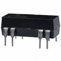
8L SERIES/SPARTAN DIP REED RELAYS
8L Series Economy DIP Reed Relays
The Coto 8L Spartan Series relays combine Coto quality and economy in the industry
standard 14 pin molded DIP package. This series will cross to all competitive DIP
packages and is ideal for telecom, security, and other general purpose applications.
8L Series Features
u Drop-in low cost replacement for industry standard DIP packages
u Contact forms; 1A, 2A and 1C available
u Available coils in 5V, 12V and 24V
u Molded thermoset body on integral lead frame design
u Hermetically Sealed Contacts
u Optional Electrostatic Shield and Coil Suppression Diode
u UL File #E67117 - Contact factory for details
u RoHS compliant
DIMENSIONS
in Inches (Millimeters)
Model 8L01, 8L02 & 8L41
14 13
9
Model 8L61
8
14
13
9
8
1
2
6
7
IDENTIFIES PIN #1
1
2
6
7
.775 Max.
(19.50)
.775 (19.68) Max.
.300
(7.62)
IDENTIFIES PIN #1
.270
(6.85)
.260
(6.60)
.080 Typ.
(2.00)
.260
(6.60)
.140 (3.55)
.100 (2.54)
.600(15.24)
.015
(0.38)
.020
(0.51)
.270
(6.58)
.100
(2.54)
.013
(0.33)
.300
(7.62)
.360
(9.14)
.500
(12.7)
.600
(15.24)
.333
(8.46)
Ordering Information
Alternate Package #1 for 8L01, 8L02 & 8L41
14 13
1
2
Alternate Package #2 for 8L01, 8L02 & 8L41
9
8
14 13
9
8
6
7
1
6
7
.77(19.60) Max.
2
.27
(6.90) Max.
.276(7.00)
.27
(6.90) Max.
.100(2.54)
.600(15.24)
Shield Option4
0=No Shield
1=Electrostatic Shield
Coil Voltage
05=5 volts
12=12 volts
24=24 volts
.768 (19.50) Max.
IDENTIFIES PIN #1
.125(3.18)
Part Number 8LXX-XX-XX1
Model Number
Diode Option3
8L01 8L41 8L61
0=No Diode 1=Diode
.015
(0.38)
.018
(0.46)
.355
(8.50)
.016
(.40) .217(5.50)
.118
(3.00)
.020(.50)
.100(2.54)
.600(15.24)
.010(.25)
.305(7.75)
.350(8.9) MAX
Ordering Information
Part Number 8LXX-XX-XX
Model Number
Diode Option3
8L02
0=No Diode 1=Diode
Shield Option4
0=No Shield
1=Electrostatic Shield
Coil Voltage
05=5 volts
12=12 volts
24=24 volts
tel: (401) 943.2686
06292019
|
fax: (401) 942.0920
�MODEL NUMBER
Parameters
Test Conditions
Units
8L012,3,4
8L022,3,4
8L412,3,4
8L612,3,4,5
1 Form A
2 Form A
1 Form C
1 Form C
COIL SPECS.
Nom. Coil Voltage
VDC
5
12
24
5
12
24
5
12
24
5
12
24
Max. Coil Voltage
VDC
6.5
15
32
6.5
15
32
6.5
15
32
6.5
15
32
Coil Resistance
500 500 2150 200 500 2000 200 500 2000 200 500 2000
+/- 10%, 25° C
Ω
Operate Voltage
Must Operate by
VDC - Max.
3.8
9.6 19.2 3.8
Release Voltage
Must Release by
VDC - Min.
0.5
1.0
2.0
0.5
9.6 19.2 3.8
9.6
19.2 3.8
9.6 19.2
1.0
1.0
2.0
1.0
2.0
0.5
0.5
2.0
CONTACT RATINGS
Switching Voltage
Max DC/Peak AC Resist.
Volts
200
200
100
100
Switching Current
Max DC/Peak AC Resist.
Amps
0.5
0.5
0.25
0.25
Carry Current
Max DC/Peak AC Resist.
Amps
1.0
1.0
0.5
0.5
Contact Rating
Max DC/Peak AC Resist.
Watts
10
10
3
3
Life Expectancy-Typical1
Signal Level 1.0V, 10mA
x 106 Ops.
500
500
100
100
Static Contact
Resistance (max. init.)
50mV, 10mA
Ω
0.150
0.150
0.200
0.200
Dynamic Contact
Resistance (max. init.)
50mV, 50mA
at 100 Hz, 1.5 msec
Ω
N/A
N/A
N/A
N/A
Insulation Resistance
(minimum)
Between all Isolated Pins
at 100V, 25°C, 40% RH
Ω
1010
1010
109
109
Capacitance - Typical
Across Open Contacts
No Shield
Shield Floating
Shield Guarding
pF
pF
pF
0.5
1.0
0.5
0.5
0.5
0.2
1.5
1.5
1.0
1.5
1.5
1.0
Open Contact to Coil
No Shield
Shield Floating
Shield Guarding
pF
pF
pF
1.5
2.0
0.5
1.5
2.0
0.5
1.5
2.0
0.5
1.5
2.0
0.5
Contact to Shield
No Shield
Shield Floating
Shield Guarding
pF
2.0
1.5
2.0
2.0
Dielectric Strength
(minimum)
Between Contacts
Contacts to Shield
Contacts/Shield to Coil
VDC/peak AC
VDC/peak AC
VDC/peak AC
250
1500
1500
250
1500
1500
200
1500
1500
200
1500
1500
Operate Time - including
bounce - Typical
At Nominal Coil Voltage,
30 Hz Square Wave
msec.
0.5
0.5
1.0
1.0
No Suppression
msec.
0.5
0.5
1.0
1.0
RELAY SPECIFICATIONS
Release Time - Typical
Top View:
Dot stamped on top of relay refers to pin #1 location
Grid = .1”x.1” (2.54mm x 2.54mm)
1
2
14 1
13 2
6
9
8
7
6
7
14
13
1
2
14
13
1
2
14
13
9
8
6
9
8
6
9
8
7
7
Notes:
Consult factory for life expectancy at other switching loads.
Molded depression on top of relay refers to pin #1 location.
3
Optional coil suppression diode across pins 2(+) and 6(-).
4
Optional ES Shield is tied to pin 9.
5
Surface mount processing temperature: 260ºC max for 1
minute dwell time. Temperature measured on lead where
lead exits molded package.
1
2
Environmental Ratings:
Storage Temp: -35°C to +100°C; Operating Temp: -20°C to +85°C;
Solder Temp: 270°C max; 10 sec. max
All electrical parameters measured at 25°C unless otherwise specified.
Vibration: 20 G’s to 2000 Hz; Shock: 50 G’s
06292019
For most recent data visit www.cotorelay.com
COTO TECHNOLOGY, INC.
�
很抱歉,暂时无法提供与“8L02-05-10”相匹配的价格&库存,您可以联系我们找货
免费人工找货- 国内价格 香港价格
- 1+60.982621+7.62753
- 10+54.3584710+6.79900
- 25+51.9074725+6.49244
- 50+50.1287850+6.26997
- 100+48.40905100+6.05487
- 250+46.22436250+5.78161
- 500+44.63618500+5.58297
- 1000+43.101541000+5.39102
- 国内价格
- 1+67.58640
- 200+26.96760
- 500+26.07120
- 1000+25.62840
