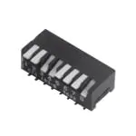
Series 193
Side Actuated DIP Switch
Coplanarity: 0.1mm/.004” maximum
Enclosed actuators shield contacts from foreign
particles throughout life of switch
Integral terminal and contact locked into high
temperature plastic base
Gold plated contacts for long-term contact
corrosion resistance
Description
The gold plated contact lock-over-center design provides positive detent action for CTS 193 Series. Optimized
active contact design incorporates a high contact force, dimple wiping action interface, making it the ideal
choice for any network or security system.
Ordering Information
Series
Number of Actuator
193-
Actuator Length B
XX
20212124
Code
2
3
4
5
6
7
8
9
10
1
M
2
1
Bottom Seal
Package
S
R
S
Shipping Position
NRRRTTT T
E
No. of switch
positions
2 positions
3 positions
4 positions
5 positions
6 positions
7 positions
8 positions
9 positions
10 positions
S
Code
BLANK
N
Code
Spec.
M
Medium actuator (1.14mm/.045”)
Code
Blank
R
Spec.
Ship at OFF position
Ship at ON position
Spec.
Anti-static tube packaging
Tape and reel packaging
( Not available for 7 position switch)
Notes: Contact CTS for other common features not listed.
2020-10-21 Rev. D
www.ctscorp.com
T
TTT
T
TSS
Page 1 of 6
© 2020 CTS® Corporation. Information/product(s) subject to change. No warranty that product(s) will meet the stated specifications for customer specific applications or test
equipment. Visit www.ctscorp.com for list of applicable patent(s), more information, or to request a quote.
T
T
T
�Series 193
Side Actuated DIP Switch
Electrical Specifications
Parameter
Circuit
Contact Resistance
Insulation Resistance
Dielectric Strength
Actuation Life
Switch Capacitance
Conditions & Remarks
Min
Max
Unit
SPST
2
10
positions
50
100
milliohms
Initial
At end of life
Between insulated terminals
500 VAC between adjacent
switches
50mA @ 24 VDC
Between adjacent closed
switches
1000
Nonswitching Rating
megohms
1
minute
7,000
cycles
5.0
pF
100
or
50
mA
or
VDC
Mechanical and Environmental
Soldering
MSL
RoHS
Shock
Vibration
Seal
Marking
Packaging:
Operating Temperature
Range
Storage Temperature
Range
Maximum reflow temperature, 250°C for 30 seconds
Level 1
Lead-Free. Fully compliant to RoHS Directive 2011/65/EU
Per MIL-STD-202F, method 213B, condition A ( 50G’s)
with no contact inconsistencies greater than 1 microsecond
Per MIL-STD-202F, method 204D, condition B ( .06” or 15G’s between 10 HZ to 2K HZ) with
no contact inconsistencies greater than 1 microsecond
Bottom seal standard
Special side or top marking available-consult CTS
Standard anti-static tube packaging, optional tape & reel packaging
-40°C to +85°C
-40°C to +85°C
Soldering Profile
2020-10-21 Rev. D
www.ctscorp.com
Page 2 of 6
© 2020 CTS® Corporation. Information/product(s) subject to change. No warranty that product(s) will meet the stated specifications for customer specific applications or test
equipment. Visit www.ctscorp.com for list of applicable patent(s), more information, or to request a quote.
�Series 193
Side Actuated DIP Switch
Mechanical Specifications
2020-10-21 Rev. D
www.ctscorp.com
Page 3 of 6
© 2020 CTS® Corporation. Information/product(s) subject to change. No warranty that product(s) will meet the stated specifications for customer specific applications or test
equipment. Visit www.ctscorp.com for list of applicable patent(s), more information, or to request a quote.
�Series 193
Side Actuated DIP Switch
Packing: Tape and Reel
Unit: mm
SW Section
2
3
4
5
6
8
9
10
12
F Fig
I
I
I
II
II
II
II
II
II
Bo
W
F
7.15
9.69
12.23
14.81
17.35
22.40
24.94
27.48
32.56
24.0
24.0
24.0
32.0
32.0
44.0
44.0
44.0
44.0
11.50
11.50
11.50
14.20
14.20
20.20
20.20
20.20
20.20
S
28.4
28.4
40.4
40.4
40.4
40.4
FIG I
FIG II
2020-10-21 Rev. D
www.ctscorp.com
Page 4 of 6
© 2020 CTS® Corporation. Information/product(s) subject to change. No warranty that product(s) will meet the stated specifications for customer specific applications or test
equipment. Visit www.ctscorp.com for list of applicable patent(s), more information, or to request a quote.
�Series 193
Side Actuated DIP Switch
SPECIFIED REEL PARTS DIMENSIONS:
Unit: mm
SW Section
F W1
2~4
5~6
8~12
24.4
32.4
44.4
W2
W3
30.4 MAX.
38.4 MAX.
50.4 MAX.
23.9 MIN./27.4 MAX.
31.9 MIN./35.4 MAX.
43.9 MIN./47.4 MAX.
(SEE PICTURE FIG)
W3 ( INCLUDES FLANGE DISTORTION
AT OUTER EDGE)
W2 ( MEASURED AT HUB )
100
330
W1 ( MEASURED AT HUB )
1.
2.
3.
4.
TAPE SPROCKET HOLE PITCH : 4.0 ± 0.1MM
ALL SMT ASSEMBLING MACHINES WILL PICK-UP THE COMPONENT FROM THE POINT, WHICH
IS LOCATED IN THE CENTRE OF TWO ADJACENT SPROCKET HOLES IN FEEDING DIRECTION. THIS
MUST BE TAKEK INTO ACCOUNT WHEN DESIGNING THE LOCATION OF THE COMPONENT IN
T&R POCKET.
RECOMMENDED PART ORIENTATION IN TAPE & REEL POCKET.
ORIENT SWITCH TERMINAL #1 TO THE SIDE OF ROUND SPROCKET HOLES, SEE PICTURE BELOW.
LENGTH OF TAPE
5. THERE SHALL BE A LEADER OF 390mm MINIMUM WHICH IS SEALED ONTO EMPTY CARRIER
TAPE, SEE PICTURE BELOW.
2020-10-21 Rev. D
www.ctscorp.com
Page 5 of 6
© 2020 CTS® Corporation. Information/product(s) subject to change. No warranty that product(s) will meet the stated specifications for customer specific applications or test
equipment. Visit www.ctscorp.com for list of applicable patent(s), more information, or to request a quote.
�Series 193
Side Actuated DIP Switch
FEEDING DIRECTION
2020-10-21 Rev. D
www.ctscorp.com
Page 6 of 6
© 2020 CTS® Corporation. Information/product(s) subject to change. No warranty that product(s) will meet the stated specifications for customer specific applications or test
equipment. Visit www.ctscorp.com for list of applicable patent(s), more information, or to request a quote.
�
很抱歉,暂时无法提供与“193-2MSR”相匹配的价格&库存,您可以联系我们找货
免费人工找货