0
登录后你可以
  • 下载海量资料
  • 学习在线课程
  • 观看技术视频
  • 写文章/发帖/加入社区
会员中心
创作中心
发布
  • 发文章

  • 发资料

  • 发帖

  • 提问

  • 发视频

创作活动
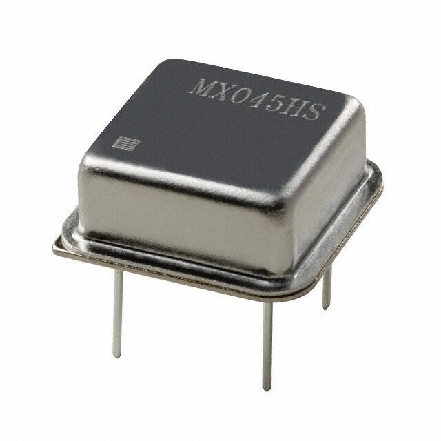
MXO45HS-2I-2M457600

MXO45HS-2I-2M457600

  • 厂商:

    CTS(西迪斯)

  • 封装:

    XO-4P_13.2X13.2MM_TM

  • 描述:

    有源晶振 2.4576MHz 5V DIP-8

  • 详情介绍
  • 数据手册
  • 价格&库存
MXO45HS-2I-2M457600 数据手册
MXO45 & MXO45HS HCMOS/TTL Clock Oscillators Features        Standard 14-Pin or 8-Pin Metal DIP Packages Fundamental and 3rd Overtone Crystal Designs Low Phase Jitter Performance Frequency Range 1 – 200MHz +5.0V Operation Output Enable Option Available Three Approved Packing Methods. Part Dimensions: 20.8 × 13.2 × 5.1mm • 3.774537g 13.2 × 13.2 × 5.5mm • 2.206637g Applications     Computers & Peripherals Storage Area Networking Broadband Access Microcontrollers/FPGAs     Networking Equipment Ethernet/Gigabit Ethernet Fiber Channel Test and Measurement Description CTS MXO45 and MXO45HS are legacy thru-hole clock oscillators that offer a low cost design supporting older HCMOS/TTL applications. MXO45/MXO45HS is not recommended for new design activity, but is available to support existing applications developed for the full and half-size metal DIP packages. Ordering Information Package Type/ Output Enable 45 Model MXO Code 45 45T 45HS 45HST - Frequency Stability 3 Package/Enable 14-Pin DIP/STD Output [no enable] 14-Pin DIP/Output Enable 8-Pin DIP/STD Output [no enable] 8-Pin DIP/Output Enable Temperature Range C Frequency Code [MHz] - XXXMXXXXXX Code Frequency Code Temp. Range -20°C to +70°C C -40°C to +85°C I Code 6 5 3 2 Stability ±20ppm 1 ±25ppm ±50ppm ±100ppm Product Frequency Code 2 Notes: 1] Consult factory for availability of 6C Stability/Temperature combination. The 6I combination is not available. 2] Frequency is recorded with 1, 2 or 3 leading significant digits before and 6 significant digits [including zeroes] after the "M". [Ex. 3.579545MHz = 3M57954, 14.31818MHz = 14M318180, 25MHz = 25M000000, 125MHz = 125M000000] Not all performance combinations and frequencies may be available. Contact your local CTS Representative or CTS Customer Service for availability. This product is specified for use only in standard commercial applications.  Supplier disclaims all express and implied warranties and liability in connection with any use of this product in any non-commercial applications or in any application that may expose the product to conditions that are outside of the tolerances provided in its specification. DOC# 008-0258-0 Rev. J Page 1 of 5 ©2017 CTS® Corporation. Information/product(s) subject to change. No warranty that product(s) will meet the stated specifications for customer specific applications or test equipment. Visit www.ctscorp.com for list of applicable patent(s), more information, or to request a quote. MXO45 & MXO45HS HCMOS/TTL Clock Oscillators Electrical Specifications Operating Conditions P ARAMETER SYMBO L CO NDITIO NS MIN TYP MAX UNIT Maximum Supply Voltage VCC - -0.5 - 7.0 V Supply Voltage VCC ±10% 4.5 5.0 5.5 V Supply Current Freq Range [tested load noted for TYP values.] ICC 1.0MHz to 20MHz [CL = 30pF] - 10 26 20.001MHz to 40MHz [CL = 30pF] - 20 40 40.001MHz to 80MHz [CL = 30pF] - 30 60 80.001MHz to 125MHz [CL = 15pF] - 40 70 - 55 125.001MHz to 200MHz [CL = 15pF] O perating Temperature Storage Temperature -20 80 +70 TA - TSTG - -40 SYMBO L CO NDITIO NS MIN fO - 1 - 200 MHz Δf/fO - 20, 25, 50 or 100 ±ppm Δf/f25 First Year @ +25°C, nominal VCC -40 +25 mA +85 °C - +100 °C TYP MAX UNIT Frequency Stability P ARAMETER Frequenc y Range Frequenc y Stability [Note 1] Aging -5 ±3 5 ppm TYP MAX UNIT 1.] Inclusive of initial tolerance at time of shipment, changes in supply voltage, load, temperature and 1st year aging. Output Parameters P ARAMETER SYMBO L CO NDITIO NS O utput Type - - O utput Load CL VOH O utput Voltage Levels VOL O utput Current Levels O utput Duty Cyc le - 1.0MHz to 50MHz [CMOS Load] - 15 50 50.001MHz to 80MHz [CMOS Load] - 15 30 80.001MHz to 200MHz [CMOS Load] - 15 15 1.0MHz to 200MHz [TTL Load] - - 10 CMOS Load 0.9VCC - - 10TTL Load 2.4 - - CMOS Load - - 0.1VCC 10TTL Load - - 0.4 VOH = 3.9V, VCC = 4.5V - - -16 IOL VOL = 0.4V, VCC = 4.5V - - 16 SYM @ 50% Level 45 - 55 1.0MHz to 20MHz [CL = 30pF] - 8 10 pF TTL V mA % @ 10%/90% Levels [tested load noted for TYP values.] TR, TF DOC# 008-0258-0 Rev. J HCMOS IOH Rise and Fall Time Start Up Time MIN TS 20.001MHz to 80MHz [CL = 30pF] - 5 8 80.001MHz to 125MHz [CL = 15pF] - 2.5 5 125.001MHz to 200MHz [CL = 15pF] - - 2 Application of VCC, CL = 15pF - 5 10 ns ms Page 2 of 5 ©2017 CTS® Corporation. Information/product(s) subject to change. No warranty that product(s) will meet the stated specifications for customer specific applications or test equipment. Visit www.ctscorp.com for list of applicable patent(s), more information, or to request a quote. MXO45 & MXO45HS HCMOS/TTL Clock Oscillators Electrical Specifications Output Parameters P ARAMETER SYMBO L CO NDITIO NS MIN TYP MAX UNIT Enable Func tion Enable Input Voltage VIH Pin 1 Logic '1', Output Enabled 2.0 - - V Disable Input Voltage VIL Pin 1 Logic '0', Output Disabled - - 0.8 V Disable Current Enable Time P hase Jitter, RMS IIL Pin 1 Logic '0', Output Disabled - 10 15 mA TPLZ Pin 1 Logic '1', Output Enabled - - 200 ns tjrms Bandwidth 12 kHz - 20 MHz - 0.7 1.0 ps Enable Truth Table Pin 1 Pin 8 or Pin 5 Logic ‘1’ Output Open Logic ‘0’ Output High Imp. Test Circuit HCMOS Output Waveform HCMOS DOC# 008-0258-0 Rev. J Page 3 of 5 ©2017 CTS® Corporation. Information/product(s) subject to change. No warranty that product(s) will meet the stated specifications for customer specific applications or test equipment. Visit www.ctscorp.com for list of applicable patent(s), more information, or to request a quote. MXO45 & MXO45HS HCMOS/TTL Clock Oscillators Mechanical Specifications Package Drawing – DIP-14 Marking Information MXO45 XXXMXXXXXX CTS ST ● YYWW ** Package Drawing - DIP-8 1. Model Name: DIP-14 – MXO45 or MXO45T DIP-8 – MXO45HS or MXO45HST 2. xxxMxxxxxx – Frequency is marked with 1,2 or 3 leading significant digits before the “M” and 6 digits after the “M” [including zeroes]. Ex. xMxxxxxx [3M579545] xxMxxxxxx [14M318180] xxMxxxxxx [25M000000] xxxMxxxxxx [125M000000] 3. ST – Frequency Stability/Temperature Code. [Refer to Ordering Information] 4. YYWW – Date Code; YY – year, WW – week. 5. ** - Manufacturing Site Code. Notes MXO45HS XXXMXXXXXX CTS ST ● YYWW ** 1. JEDEC termination code (e1). Lead finish is tinsilver-copper [SnAgCu]. 2. Reflow conditions per JEDEC J-STD-020; +260°C maximum, 20 seconds. 3. Hand soldering conditions; solder iron temperature +350°C maximum, 10 seconds. 4. MSL = 1. Pin Assignments Pin Symbol Function 1 7 or 4 EOH GND Enable Circuit & Package Ground 8 or 5 14 or 8 Output VCC RF Output Supply Voltage DOC# 008-0258-0 Rev. J Page 4 of 5 ©2017 CTS® Corporation. Information/product(s) subject to change. No warranty that product(s) will meet the stated specifications for customer specific applications or test equipment. Visit www.ctscorp.com for list of applicable patent(s), more information, or to request a quote. MXO45 & MXO45HS HCMOS/TTL Clock Oscillators Packaging - CTS Approved Methods Anti-Static Foam in Cardboard Carton Typical packing format: 1. 50pcs. per anti-static foam layer. 2. 2 layers of anti-static foam [100pcs.] per inner cardboard carton. Carton size is approximately 170mm x 120mm x 45mm [LxWxH]. 3. An anti-static foam sheet layer is placed as a buffer on top of each layer containing oscillators. 4. Master-pack multiple inner cartons in a larger outer cardboard carton. 20 inner cartons [100pcs. per carton] per outer carton, is approximately 550mm x 350mm x 180mm [LxWxH]. Anti-Static Plastic Trays Typical packing format: 1. 50pcs. per plastic tray. Tray size is approximately 180mm x 136mm x 18mm [LxWxH]. 2. 2 trays per anti-static bag [100pcs.] or 10 trays per anti-static bag [500pcs.] Bag height for 10 trays is approximately 175mm. 3. One anti-static bag per inner cardboard carton. 4. Master-pack multiple inner cartons in a larger outer cardboard carton. 8 inner cartons [10 trays per carton] per outer carton, is approximately 460mm x 380mm x 400mm [LxWxH]. Anti-Static Plastic Tubes Typical packing format: 1. 10pcs. per plastic tube – Full-Size package. 15pcs. per plastic tube – Half-Size package. 2. Plastic tubes are master packed in cardboard carton. Carton is approximately 35mm x 35mm x 20mm [LxWxH]. DOC# 008-0258-0 Rev. J Page 5 of 5 ©2017 CTS® Corporation. Information/product(s) subject to change. No warranty that product(s) will meet the stated specifications for customer specific applications or test equipment. Visit www.ctscorp.com for list of applicable patent(s), more information, or to request a quote.
MXO45HS-2I-2M457600
物料型号:MXO45和MXO45HS

器件简介: - 这些是传统的通孔时钟振荡器,适用于旧的HCMOS/TTL应用,提供低成本设计。 - MXO45/MXO45HS不推荐用于新的设计活动,但可用于支持为全尺寸和半尺寸金属DIP封装开发现有应用。

引脚分配: - 1号引脚:使能(Enable) - 7或4号引脚:电路和封装地(GND) - 8或5号引脚:输出(RF Output) - 14或8号引脚:供电电压(Vcc)

参数特性: - 工作频率范围:1MHz至200MHz - 供电电压:+5.0V - 标准14针或8针金属DIP封装 - 基本和三次谐波晶体设计 - 低相位抖动性能 - 可选的输出使能选项

功能详解: - 提供了详细的电气规格,包括工作条件、频率稳定性、输出参数等。 - 包括了使能功能的详细描述,例如使能输入电压、禁用输入电压、禁用电流、使能时间等。 - 提供了相位抖动、上升和下降时间等性能参数。

应用信息: - 适用于计算机和外围设备、存储区域网络、网络设备、以太网/千兆以太网、宽带接入、微控制器/FPGAs、光纤通道和测试测量设备。

封装信息: - 提供了DIP-14和DIP-8两种封装的机械规格图和尺寸。 - 标记信息包括型号名称、频率、稳定性/温度代码、日期代码和制造地点代码。

订购信息: - 提供了详细的订购指南,包括频率稳定性、封装类型/输出使能、温度范围和频率代码。

注意事项: - 产品仅适用于标准商业应用,供应商对产品在任何非商业应用或可能使产品暴露于规格之外条件的任何使用不承担任何明示或暗示的保证。
MXO45HS-2I-2M457600 价格&库存

很抱歉,暂时无法提供与“MXO45HS-2I-2M457600”相匹配的价格&库存,您可以联系我们找货

免费人工找货