Additional Resources:
Product Page
|
3D Model
date
06/11/2015
page
1 of 7
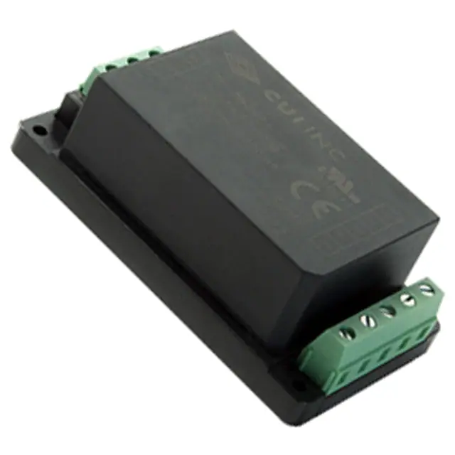
SERIES: VSK-S20-T │ DESCRIPTION: AC-DC POWER SUPPLY
FEATURES
•
•
•
•
•
•
•
up to 20W continuous power
compact chassis mount design
universal input (85~264 Vac / 100~370 Vdc)
single, regulated output from 3.3~24 Vdc
over voltage, over current, and short circuit protections
UL/cUL safety approvals
efficiency up to 85%
MODEL
output
voltage
output
current
output
power
ripple
and noise1
efficiency
(Vdc)
max
(A)
max
(W)
typ
(mVp-p)
typ
(%)
3.3
4.1
13.5
50
74
VSK-S20-5U-T
5
3.5
17.5
50
78
VSK-S20-9U-T
9
2.1
20
50
80
VSK-S20-12U-T
12
1.6
20
50
82
VSK-S20-15U-T
15
1.3
20
50
83
VSK-S20-24U-T
24
0.85
20
50
85
VSK-S20-3R3U-T
Notes:
1. Ripple and noise are measured at 20 MHz BW by “parallel cable” method with 1 uF ceramic and 10 uF electrolytic capacitors on the output.
PART NUMBER KEY
VSK-S20 - XXU - T
Base Number
Output Voltage
cui.com
�Additional Resources:
Product Page
|
3D Model
CUI Inc │ SERIES: VSK-S20-T │ DESCRIPTION: AC-DC POWER SUPPLY
date 06/11/2015 │ page 2 of 7
INPUT
parameter
conditions/description
min
voltage
frequency
max
units
85
100
typ
264
370
Vac
Vdc
47
63
Hz
600
340
mA
mA
current
at 115 Vac
at 230 Vac
inrush current
at 115 Vac
at 230 Vac
16
30
A
A
leakage current
at 230 Vac, 50 Hz (RMS)
0.1
mA
input fuse
3.15 A/250 V, slow-blow type (included on chassis)
OUTPUT
parameter
conditions/description
capacitive load
3.3 Vdc output model
5 Vdc output model
9 Vdc output model
12 Vdc output model
15 Vdc output model
24 Vdc output model
line regulation
at full load
load regulation
at 10~100% load
min
voltage set accuracy
adjustability
hold-up time
at 115 Vac
at 230 Vac
switching frequency
temperature coefficient
typ
max
units
48,000
12,000
7,200
5,400
2,700
1,800
μF
μF
μF
μF
μF
μF
±0.5
%
±1
%
±2
%
±10
%
15
80
ms
ms
65
kHz
±0.02
%/°C
PROTECTIONS
parameter
conditions/description
min
over current protection
auto restart
110
short circuit protection
continuous, auto restart
over voltage protection
3.3 Vdc output model
5 Vdc output model
9 Vdc output model
12 Vdc output model
15 Vdc output model
24 Vdc output model
typ
max
units
%
7.5
7.5
12
20
20
30
Vdc
Vdc
Vdc
Vdc
Vdc
Vdc
max
units
SAFETY & COMPLIANCE
parameter
conditions/description
isolation voltage
input to output for 1 minute
input to ground for 1 minute
safety approvals
UL60950-1, CE
safety class
class I
conducted emissions
CISPR22/EN55022, Class B
radiated emissions
CISPR22/EN55022, Class B
ESD
IEC/EN61000-4-2 Class B, contact ±6 kV/air ±8 kV
radiated immunity
IEC/EN61000-4-3 Class A, 10V/m
EFT/burst
min
typ
3,000
2,000
IEC/EN61000-4-4 Class B, ±2 kV
IEC/EN61000-4-4 Class B, ±4 kV (external circuit required, see figure 2)
cui.com
Vac
Vac
�Additional Resources:
Product Page
|
3D Model
CUI Inc │ SERIES: VSK-S20-T │ DESCRIPTION: AC-DC POWER SUPPLY
date 06/11/2015 │ page 3 of 7
SAFETY & COMPLIANCE (CONTINUED)
parameter
conditions/description
surge
IEC/EN61000-4-5 Class B, ±1 kV/±2 kV
IEC/EN61000-4-5 Class B, ±2 kV/±4 kV (external circuit required, see figure 2)
min
typ
max
conducted immunity
IEC/EN61000-4-6 Class A, 10 Vr.m.s
PFM
IEC/EN61000-4-8 Class A, 10 A/m
voltage dips & interruptions
IEC/EN61000-4-11 Class B, 0%-70%
MTBF
as per MIL-HDBK-217F at 25°C
RoHS
2011/65/EU
300,000
units
hrs
ENVIRONMENTAL
parameter
conditions/description
min
operating temperature
see derating curves
storage temperature
storage humidity
typ
max
units
-40
70
°C
-40
105
°C
95
%
non-condensing
DERATING CURVES
Safe operating area
40
75
60
Safe operating area
40
20
-10 -5
5
60
Safe operating area
40
20
25
35
45
Ambient Temperature (°C)
55
65 70 75
85
95 100 105
115
125
235 240 245
Input Voltage (Vac)
cui.com
255
264
~
~
-40
75
~
~
20
100
Load (%)
Load (%)
60
load vs. input voltage (Vdc)
(at 25°C)
~
~
~
~
100
80
~
~
Load (%)
100
load vs. input voltage (Vac)
(at 25°C)
~
~
load vs. ambient temperature
(at 100~240 Vac)
100
120
340
Input Voltage (Vdc)
370
�Additional Resources:
Product Page
|
3D Model
CUI Inc │ SERIES: VSK-S20-T │ DESCRIPTION: AC-DC POWER SUPPLY
date 06/11/2015 │ page 4 of 7
MECHANICAL
parameter
conditions/description
dimensions
96.10 x 54.00 x 32.00 (3.783 x 2.126 x 1.259 inch)
min
case material
UL94V-0
typ
units
mm
weight
170
cooling
max
g
convection cooling
MECHANICAL DRAWING
units: mm[inches]
tolerance: ±0.50[±0.020]
�����>�����@
�����>�����@
����>�����@
PIN CONNECTIONS
1
FUNCTION
GND
2
AC(N)
3
AC(L)
4
-Vo
5
NC
6
TRIM
7
NC
8
+Vo
�
�
�
�
�
�
�
�
Top View
������>�����@
PIN
������>�����@
������>�����@
wire range: 24~12 AWG
����>�����@
�����>�����@
Side View
cui.com
��
�Additional Resources:
Product Page
|
3D Model
CUI Inc │ SERIES: VSK-S20-T │ DESCRIPTION: AC-DC POWER SUPPLY
date 06/11/2015 │ page 5 of 7
TYPICAL APPLICATION CIRCUIT
Figure 1
AC(L)
FU S E
AC(L)
C1
+Vo
T VS 1
C2
AC / DC
M OV 1
LOAD
AC(N)
AC(N)
-Vo
Table 1
Recommended External Circuit Components
Note:
MODEL
FUSE1
MOV1
C1
C2
TVS
VSK-S20-3R3U-T
3.15A/250V
S14K350
1µF
330μF
SMBJ7.0A
VSK-S20-5U-T
3.15A/250V
S14K350
1µF
330μF
SMBJ7.0A
VSK-S20-9U-T
3.15A/250V
S14K350
1µF
220μF
SMBJ12A
VSK-S20-12U-T
3.15A/250V
S14K350
1µF
220μF
SMBJ20A
VSK-S20-15U-T
3.15A/250V
S14K350
1µF
220μF
SMBJ20A
VSK-S20-24U-T
3.15A/250V
S14K350
1µF
220μF
SMBJ30A
1. Fuse included on chassis
EMC RECOMMENDED CIRCUIT
Figure 2
FUSE
LDM
LCM
AC(L)
AC( L)
+Vo
CY1
MOV1
CY2
-Vo
AC(N)
AC(N)
Table 2
Recommended External Circuit Components
Note:
MOV1
S14K350
CY1, CY2
1000pF/400Vac
CX
0.1μF/275Vac
LCM
10mH
LDM
4.7μH/2A
Also refer to Table 1
cui.com
C2
TVS1
+
ACDC
CX
C1
RL
�Additional Resources:
Product Page
|
3D Model
CUI Inc │ SERIES: VSK-S20-T │ DESCRIPTION: AC-DC POWER SUPPLY
date 06/11/2015 │ page 6 of 7
APPLICATION NOTES
1. Output voltage trimming
Leave open if not used.
Figure 3
Application Circuit for Trim pin
(part in broken line is the interior of models)
+ Vo
+Vo
R1
V re f
Formula for Trim Resistor
R3
V re f
aR 2
R2-a
-R3
a=
Vref
R1
Vo’ - Vref
down : R T=
aR 1
R1-a
-R3
a=
Vo’ - Vref
R2
Vref
RT
R1
Trim
up : R T=
R3
R2
RT
R2
0V
0V
Tr im up
Tr im down
Trim
Note:
Table 3
Notes:
Value for R1, R2, R3, and Vref refer to Table 3
RT: Trim Resistor
a: User-defined parameter, no actual meanings
Vo': The trim up/down voltage
Vout
(Vdc)
R1
(kΩ)
R2
(kΩ)
R3
(kΩ)
Vref
(V)
3.3
3.3
1.98
1
1.24
5
3.3
3.3
1
2.5
9
7.5
2.87
1
2.5
12
3.83
1
1
2.5
15
7.5
1.5
1
2.5
24
8.66
1
1
2.5
1. Output filtering capacitor C2 is an electrolytic capacitor, It is recommended to use high frequency and low impedance electrolytic capacitors. For capacitance and current
of capacitor please refer to manufacture’s datasheet. Voltage derating of capacitor should be 80% or above. C1 is used to filter high frequency noise. TVS is
recommended component to protect post-circuits (when converter fails).
2. All specifications measured at Ta=25C, humidity
很抱歉,暂时无法提供与“VSK-S20-5U-T”相匹配的价格&库存,您可以联系我们找货
免费人工找货- 国内价格
- 1+634.74840
- 204+253.27080
- 504+244.80360
- 996+240.62400