rev. page date 1 of 5
02/2010
PART NUMBER: C14
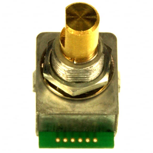
DESCRIPTION: panel mount optical encoder
ELECTRICAL SPECIFICATIONS
supply voltage supply current output code power consumption angle of throw 5 V dc ±5% (optional: 3.3 V dc ±10%) 20 mA max. (open collector) 2-bit Quadature, Channel A leads Channel B by 90° with clockwise rotation 100 mW 22.5° for code change and 16 detent positions 11.25° for code change and 32 detent positions
MECHANICAL SPECIFICATIONS
operational torque without detent 16 position w/detent 32 position w/detent radial thrust 0.2 N·cm (20.4 gf·cm max.) 0.4 ±0.2 N·cm (40.8 ±20.4 gf·cm) 0.4 ±0.2 N·cm (40.8 ±20.4 gf·cm) 100 N·cm (10.2 kgf·cm) 10 N (1.02 kgf) 15 N (1.53 kgf) 1,000,000 cycles 11 g
mounting torque shaft strength rotational life weight (approx)
PUSH SWITCH SPECIFICATIONS
rated voltage contact resistance insulation resistance voltage proof operating force travel bounce life 12 V dc, 50 mA 200 mΩ max. 100 mΩ min. 250 V ac for 1 minute 4.5 ± 1 N (459 ±102 g·f) 0.5 ±0.3 mm 10 msec. 1,000,000
ENVIRONMENTAL SPECIFICATIONS
operating temp. range storage temp. range vibration shock cold proof heat proof change to temp. humidity 0° to +60° C -20 ~ 80°C frequency range: 10 ~ 55 Hz, peak to peak amplitude: 1.5 mm 50 G for 11 ms, half sine wave -20°C for 96 hours 80°C for 96 hours -10 ~ 70°C for 30 minutes each 90 ~ 95% for 96 hours at 40°C
20050 SW 112th Ave. Tualatin, Oregon 97062 phone 503.612.2300 fax 503.612.2383 phone fax
�rev. page date 2 of 5
02/2010
PART NUMBER: C14
DESCRIPTION: panel mount optical encoder
ORDERING INSTRUCTIONS
C14 X XX X - X X X X
Detent: D = with detent N = without detent Angle of throw: 16 = 22.5° for code change and 16 detent positions 32 = 11.25° for code change and 32 detent positions Input voltage: “blank” = 5 V input 3 = 3.3 V input Waterproof: “blank” = standard A = IP65
Push switch: P = with push switch N = without push switch
Termination: A = ø 0.5 mm holes B = 130 mm cable with connector C = with header I D = with header II E = horizontal PCB F = vertical PCB
Shaft diameter: 1 = 3.175 mm (1/8”) 2 = 6 mm 3 = 6.35 mm (1/4”)
CIRCUIT CONNECTION
WATER PROOF MOUNTING
Protects against ingress of water from mounting panel side only.
(3.3 V optional)
OUTPUT WAVEFORM
20050 SW 112th Ave. Tualatin, Oregon 97062 phone 503.612.2300 fax 503.612.2383 phone fax
�rev. page date 3 of 5
02/2010
PART NUMBER: C14
DESCRIPTION: panel mount optical encoder
OPTIONS
CUIINC
Mounting Hole Dimensions (for A, B, and C)
CUIINC
Mounting panel thickness: 3.5 mm max.
CUIINC
Mounting Hole dimensions and Footprint for D (±0.5 mm)
Mounting panel thickness: 3.5 mm max.
CUIINC
20050 SW 112th Ave. Tualatin, Oregon 97062 phone 503.612.2300 fax 503.612.2383 phone fax
�rev. page date 4 of 5
02/2010
PART NUMBER: C14
DESCRIPTION: panel mount optical encoder
OPTIONS CONTINUED
CUIINC
Mounting Hole Dimensions (for E and F)
Mounting panel thickness: 3.5 mm max.
CUIINC
20050 SW 112th Ave. Tualatin, Oregon 97062 phone 503.612.2300 fax 503.612.2383 phone fax
�rev. page date 5 of 5
02/2010
PART NUMBER: C14
DESCRIPTION: panel mount optical encoder
MECHANICAL DRAWING
3.175 mm
CUIINC
CUIINC
6.0 mm
CUIINC
CUIINC
6.35 mm
CUIINC
CUIINC
20050 SW 112th Ave. Tualatin, Oregon 97062 phone 503.612.2300 fax 503.612.2383 phone fax
�
很抱歉,暂时无法提供与“C14D16N-A3”相匹配的价格&库存,您可以联系我们找货
免费人工找货- 国内价格 香港价格
- 250+147.24230250+18.47159
