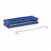
DIP Connectors
The CW Dual-In-Line Plug (DIP) connector is used for rapid, permanent connection of ribbon cable to a PC board or to a standard DIP socket when connect/disconnect capabilities are required. The cover is factory preassembled to the connector base to simplify assembly to cable and has ridges for cable alignment. CW DIP connectors are Mil-DTL-83503/6 approved.
• Beveled corner on cover and base at pin #1 provides orientation and contact identification.
• No alignment tools required. Cable fits snugly between base’s cover-support posts, and is guided into position by ridges molded into inner surface of cover.
• No special cable preparation required. Factory preassembled cover minimizes assembly time. Cable is inserted and terminated in one simple step.
• Sturdy terminal posts are strong, yet flexible enough to withstand occasional bending and straightening without fatigue. • No “bare shoulders”. No exposure of unnecessary sections of the contact and possible shorting at the PC board interface.
30
• 130 James Way, Southampton, PA 18966 - 3838 • Telephone: (215) 355-7080 • Fax: (215) 355-1088 • www.cwind.com
�Con tact
• Patented offset tines produce Torq-Tite™ termination for added reliability. • Double barbs bite into plastic, retaining contact firmly in insulator. • Spring-temper phosphor bronze contact material resists breakage during bending or straightening operations. • Two tail lengths are available for use with standard or low profile DIP sockets. .012 in. x .021 in. contact crosssection provides proper mating with a variety of DIP sockets.
DIP Con n ector Featur es
• Mil-DTL-83503/6 approved • One-piece construction. • 14, 16, 24,and 40 pin versions. • Patented Torq-Tite™ contacts, ensure reliable gas-tight terminations. • Gold-plated phosphor bronze contacts, standard tin-lead plated contacts optional. • Accepts 28-30 AWG stranded or solid conductors. • Simple assembly – bench press or low cost hand tool is all that’s needed for terminating cable and connectors. • All pin numbers clearly marked and legible before and after assembly. Numbering is arranged to meet MIL-DTL-83503 specifications for standard IC DIP numbering. • Optional strain relief clips are easily installed. Allows top center, vertical cable routing to reduce possibility of damage to contact pins during removal of DIP from socket. • Two contact tail lengths available — .175 in. standard or optional 130 in. length for mating with low profile Dip Sockets.
DIP Connectors
Str ain Relief
Optional metal strain relief straps are available. Connection is isolated from mechanical strain by the bend in the cable, as it is folded over the top of the assembled connector. The Strain Relief Strap is placed over the cable and snaps into a recess on the connector. A centralized top cable exit is created in the finished cable assembly.
Con tact Iden tification
Every contact position is numbered, per MilDTL-83503, for easy identification. In addition, a beveled corner at pin #1 enhances orientation of the connector to the mating DIP Socket, even in blind installations.
Assembly
The CT200 DIP Hand Tool is designed to terminate out 14 and 16 pin DIP Connectors. It is easy to use, lightweight and compact, making it an ideal tool for field replacement work or low volume assembly applications. DIP connectors can also be assembled to cable using CW’s CT301 76/84 Bench Press.
• 130 James Way, Southampton, PA 18966 - 3838 • Telephone: (215) 355-7080 • Fax: (215) 355-1088 • www.cwind.com
31
�DIP Connectors
Dimen sion s
14/16 Pin DIP Connector
En gin eer in g Dimen sion s
NOTCHED CORNER ORIENTS No. 1 CONTACT LOCATION. (14 CONTACT POSITIONS SHOWN, ALSO AVAILABLE WITH 16 POSITIONS.)
7 6 5 4 3 2 1
.42 (10.7) .34 (8.6)
PAT. 3,993,393 STRAIN RELIEF STRAP-OPTIONAL
8 9 10 11 12 13 14
CONNECTOR COVER SHOWN IN OPEN POSITION.
C
.32 (8.1) .248 (6.30) .012 (.30) CONTACT TYP. .300 TAIL LENGTH (7.62) ±.010 (±.25) CONNECTOR COVER SHOWN IN CLOSED POSITION.
CONNECTOR DIMENSIONS NO. OF A B C CONTACTS .60 .754 .81 14 (15.2) (19.2) (20.6) 16 .70 .854 .91 (17.8) (21.7) (23.1)
.100 (2.54) TYP.
.021 TYP. (.54)
A B (±.25)
±.010
24 Pin DIP Connector
NOTCHED CORNER ORIENTS No. 1 CONTACT LOCATION.
12 11 10 9 8 7 6 5 4 3 2 1
.72 (18.3) .35 (8.8)
PAT. 3,993,393
13 14 15 16 17 18 19 20 21 22 23 24
STRAIN RELIEF STRAP-OPTIONAL .36 (9.1)
CONNECTOR COVER SHOWN IN OPEN POSITION.
1.32 (33.5) .248 (6.30) .012 (.30) TYP.
.100 TYP. (2.54) 1.100 (27.94)
.021 (.54) TYP.
CONTACT TAIL LENGTH
±.010 (±.25)
.600 (15.24)
1.264 ±.010 (32.1 ±.25)
CONNECTOR COVER SHOWN IN CLOSED POSITION.
.72 (18.3) .35 (8.8)
40 Pin DIP Connector
NOTCHED CORNER ORIENTS No. 1 CONTACT LOCATION.
20 19 18 17 16 15 14 13 12 11 10 9 8 7 6 5 4 3 21
PAT. 3,993,393
21 22 23 24 25 26 27 28 29 30 31 32 33 34 35 36 37 38 39 40
2.12 (53.9) STRAIN RELIEF STRAP-OPTIONAL .36 (9.1) 2.067 ±.010 (52.50 ±.25) .248 (6.30)
CONNECTOR COVER SHOWN IN OPEN POSITION.
.100 TYP. (2.54)
.021 TYP. (.54) 1.900 (48.26)
CONTACT TAIL LENGTH
±.010 (±.25)
.600 (15.24)
.012 TYP. (.30)
CONNECTOR COVER SHOWN IN CLOSED POSITION.
32
• 130 James Way, Southampton, PA 18966 - 3838 • Telephone: (215) 355-7080 • Fax: (215) 355-1088 • www.cwind.com
�DIP Connectors
Specification s an d Or der in g In for mation
Specification s
• Contacts: phosphor bronze standard. • Contact Plating: 10µ in. gold over 50µ in. nickel, standard; 30µ in. gold over 50µ in. nickel, optional; 50µ in. gold over 50µ in. nickel, optional; 100µ in. tin-lead optional • Insulator Material: UL 94V-0 flame - retardant glass filled thermoplastic • Strain Relief Strap Material: tin-plated steel • Color: blue • Operating temperature: -55ºC to +125ºC • Current Rating: 1A (maximum) per contact • Dielectric Withstand Voltage: Greater than 500 Vdc at sea level • Insulation Resistance: Greater than 5 x 10⁹ ohms • Mates with .050 in. centered round conductor flat cable and standard DIP socket with .100 in. x .300 in. or .100 in. x .600 in. contact spacing • Cover pull off force, with strain relief 20 lb minimum (force along contacts’ primary axes)
How to Or der DIP Con n ector s CWR-XXX-XX-XXXX
Type of Connector Standard tail length .175” = 130 Optional tail length .130” = 134 Number of Contacts (14, 16, 24 or 40)
Plating 0000=10µ in. gold over 50µ in. nickel (standard) 0001=30µ in. gold over 50µ in. nickel 0002=50µ in. gold over 50µ in. nickel Mil-DTL-83503/6 approved. (CWR-130-14, 16, 24 only) 0003=100µ in. tin-lead
EXAMPLE: CWR-130-16-0002 is part number for a 16-pin DIP connector with .175 in. tails and 50µ in. gold over 50µ in. nickel contacts
How to Or der DIP Cable Assemblies
Cable assemblies with two DIP connectors (CWR-130-XX-0000) on a prescribed length of color-coded cable are available with connectors oriented per drawing 31-1. (#1 contacts oriented to brown conductor.) For other lengths, orientations, numbers or combinations of connectors, contact the factory or your local value-added distributor.
BROWN (No. 1 Cond.)
L
DRAWING 31-1
CA-XX-910X
Number of Conductors (14, 16, 24 or 40)
Final assembly length “L” 1=3”+1/8” 2=6”+1/8” 3=12”+1/4” 4=24”+1/4” 5=48”+1/4”
How to Or der Str ain Relief Str aps for DIP Con n ector s
EXAMPLE: Strain Relief Strap part number for 24-pin DIP Connector is CWN-SR-24
(14 and 16)
CWN-SR-XX
Connector Size (14, 16, 24 or 40)
(24 and 40)
• 130 James Way, Southampton, PA 18966 - 3838 • Telephone: (215) 355-7080 • Fax: (215) 355-1088 • www.cwind.com
33
�