CY3217
MiniProg1 Kit User Guide
Spec. # 001-66541 Rev. *A
Cypress Semiconductor
198 Champion Court
San Jose, CA 95134-1709
Phone (USA): 800.858.1810
Phone (Intnl): 408.943.2600
http://www.cypress.com
�Copyrights
Copyrights
© Cypress Semiconductor Corporation, 2011. The information contained herein is subject to change without notice. Cypress
Semiconductor Corporation assumes no responsibility for the use of any circuitry other than circuitry embodied in a Cypress
product. Nor does it convey or imply any license under patent or other rights. Cypress products are not warranted nor
intended to be used for medical, life support, life saving, critical control or safety applications, unless pursuant to an express
written agreement with Cypress. Furthermore, Cypress does not authorize its products for use as critical components in lifesupport systems where a malfunction or failure may reasonably be expected to result in significant injury to the user. The
inclusion of Cypress products in life-support systems application implies that the manufacturer assumes all risk of such use
and in doing so indemnifies Cypress against all charges.
Any Source Code (software and/or firmware) is owned by Cypress Semiconductor Corporation (Cypress) and is protected by
and subject to worldwide patent protection (United States and foreign), United States copyright laws and international treaty
provisions. Cypress hereby grants to licensee a personal, non-exclusive, non-transferable license to copy, use, modify, create
derivative works of, and compile the Cypress Source Code and derivative works for the sole purpose of creating custom software and or firmware in support of licensee product to be used only in conjunction with a Cypress integrated circuit as specified in the applicable agreement. Any reproduction, modification, translation, compilation, or representation of this Source
Code except as specified above is prohibited without the express written permission of Cypress.
Disclaimer: CYPRESS MAKES NO WARRANTY OF ANY KIND, EXPRESS OR IMPLIED, WITH REGARD TO THIS MATERIAL, INCLUDING, BUT NOT LIMITED TO, THE IMPLIED WARRANTIES OF MERCHANTABILITY AND FITNESS FOR A
PARTICULAR PURPOSE. Cypress reserves the right to make changes without further notice to the materials described
herein. Cypress does not assume any liability arising out of the application or use of any product or circuit described herein.
Cypress does not authorize its products for use as critical components in life-support systems where a malfunction or failure
may reasonably be expected to result in significant injury to the user. The inclusion of Cypress’ product in a life-support systems application implies that the manufacturer assumes all risk of such use and in doing so indemnifies Cypress against all
charges.
Use may be limited by and subject to the applicable Cypress software license agreement.
PSoC® is a registered trademark and PSoC Designer™ is a trademark of Cypress Semiconductor Corp. All other trademarks
or registered trademarks referenced herein are property of the respective corporations.
Flash Code Protection
Cypress products meet the specifications contained in their particular Cypress PSoC Data Sheets. Cypress believes that its
family of PSoC products is one of the most secure families of its kind on the market today, regardless of how they are used.
There may be methods, unknown to Cypress, that can breach the code protection features. Any of these methods, to our
knowledge, would be dishonest and possibly illegal. Neither Cypress nor any other semiconductor manufacturer can guarantee the security of their code. Code protection does not mean that we are guaranteeing the product as ‘unbreakable’.
Cypress is willing to work with the customer who is concerned about the integrity of their code. Code protection is constantly
evolving. We at Cypress are committed to continuously improving the code protection features of our products.
2
CY3217-MiniProg1 Kit Guide, Spec. # 001-66541 Rev. *A
�Contents
1. Introduction
1.1
1.2
1.3
1.4
Kit Contents .................................................................................................................5
Additional Learning Resources....................................................................................5
Document History ........................................................................................................6
Documentation Conventions .......................................................................................6
2. Getting Started
2.1
2.2
2.3
3.5
3.6
3.7
3.8
3.9
3.10
3.11
3.12
3.13
3.14
3.15
13
Introduction ................................................................................................................13
Start PSoC Programmer ............................................................................................14
Select Programmer View Options..............................................................................14
Select Programmer Options ......................................................................................15
3.4.1 Automatic Firmware Update...........................................................................15
3.4.2 Automatic Chip Reset ....................................................................................15
Select Port .................................................................................................................15
3.5.1 Programming Characteristics.........................................................................16
Select Programming Mode ........................................................................................16
Select Hex File...........................................................................................................17
Program a Device ......................................................................................................17
3.8.1 Turn Verification Off........................................................................................17
3.8.2 Verify Programming........................................................................................17
Upgrade Firmware .....................................................................................................17
Abort a Process .........................................................................................................18
Read ..........................................................................................................................18
Checksum..................................................................................................................19
Erase Flash................................................................................................................19
3.13.1 Erase a Block .................................................................................................19
3.13.2 Erase Flash Contents.....................................................................................19
Patch Image...............................................................................................................20
MiniProg1...................................................................................................................20
3.15.1 Connect MiniProg1.........................................................................................20
3.15.2 Program with MiniProg1.................................................................................21
A. Appendix
A.1
7
Installation....................................................................................................................7
PSoC Designer ..........................................................................................................11
PSoC Programmer ....................................................................................................12
3. Using MiniProg1
3.1
3.2
3.3
3.4
5
23
Programming Header ................................................................................................23
CY3217-MiniProg1 Kit Guide, Spec. # 001-66541 Rev. *A
3
�Contents
4
CY3217-MiniProg1 Kit Guide, Spec. # 001-66541 Rev. *A
�1.
Introduction
Thank you for your interest in the CY3217-MiniProg1 Kit. The MiniProg1 programmer is designed to
help hardware, firmware, and software developers in building their own systems around the Cypress
8-bit PSoC® 1 devices. You can use the CY3217-MiniProg1 kit with PSoC Designer™ and PSoC
Programmer. This kit can be used as an in-system serial programmer (ISSP) to program PSoC 1
devices. The MiniProg1 can also supply power to a target board at 5 V.
Cypress does not recommend the MiniProg1 in this kit for production programming. For production
programming, see a list of qualified vendors on the General PSoC Programming page of the
Cypress website.
1.1
Kit Contents
The CY3217-MiniProg1 Kit contains:
■
MiniProg1 programmer
■
USB A to Mini B cable
■
CY3217-MiniProg1 kit CD
❐
PSoC Designer installation file
❐
PSoC Programmer installation file
❐
Bridge Control Panel installation file (packaged along with PSoC Programmer)
❐
Kit guide
❐
Quick start guide
❐
Release notes
Inspect the contents of the kit; if any parts are missing, contact your nearest Cypress sales office for
further assistance.
1.2
Additional Learning Resources
Visit http://www.cypress.com for additional learning resources in the form of data sheets, technical
reference manual, and application notes.
■
For more information on PSoC Designer functionality, releases, and FAQ:
http://www.cypress.com/go/psocdesigner
■
For more information on PSoC Programmer, supported hardware, and COM layer:
http://www.cypress.com/go/psocprogrammer
■
For a list of PSoC Designer-related trainings:
http://www.cypress.com/?rID=40543
CY3217-MiniProg1 Kit Guide, Spec. # 001-66541 Rev. *A
5
�Introduction
1.3
Document History
Revision
PDF Creation
Date
Origin of
Change
**
07/21/2011
RKPM
Initial version of kit guide
RKPM
Updated images in section 2.1. Minor content updates throughout
the document.
*A
1.4
09/14/2011
Description of Change
Documentation Conventions
Table 1-1. Document Conventions for Guides
Convention
6
Usage
Courier New
Displays file locations, user entered text, and source code:
C:\ ...cd\icc\
Italics
Displays file names and reference documentation:
Read about the sourcefile.hex file in the PSoC Designer User Guide.
[Bracketed, Bold]
Displays keyboard commands in procedures:
[Enter] or [Ctrl] [C]
File > Open
Represents menu paths:
File > Open > New Project
Bold
Displays commands, menu paths, and icon names in procedures:
Click the File icon and then click Open.
Times New Roman
Displays an equation:
2+2=4
Text in gray boxes
Describes cautions or unique functionality of the product.
CY3217-MiniProg1 Kit Guide, Spec. # 001-66541 Rev. *A
�2.
Getting Started
This chapter describes how to install and configure the CY3217-MiniProg1 kit
2.1
Installation
To install the CY3217-MiniProg1 kit, follow these steps:
1. Insert the kit CD into the CD drive of your PC. The CD is designed to auto-run and the kit installer
startup screen appears.
You can also download the latest installer from http://www.cypress.com/go/CY3217-MiniProg1.
Three types of installers are available for download:
a. CY3217-MiniProg1_ISO: This file (ISO image) is an archive file of the optical disc provided
with the kit. You can use this to create an installer CD or extract information using WinRar or
similar tools.
b. CY3217-MiniProg1_Single Package: This executable file installs the contents of the kit CD,
which includes PSoC Programmer, PSoC Designer, and user documents.
c. CY3217-MiniProg1_Single Package (without prerequisites): This executable file installs only
the kit user documents.
2. Click Install CY3217-MiniProg1 Kit Content to start the installation, as shown in Figure 2-1.
Figure 2-1. Kit Installer Startup Screen
CY3217-MiniProg1 Kit Guide, Spec. # 001-66541 Rev. *A
7
�Getting Started
Note If auto-run does not execute, double-click the cyautorun.exe file on the root directory of the
CD, as shown in Figure 2-2. To access the root directory, click Start > My Computer >
CY3217-MiniProg1 Kit.
Figure 2-2. Root Directory of the CD
3. The InstallShield Wizard screen appears. On this screen, choose the folder location to install
the setup files. You can change the location of the folder using Change, as shown in Figure 2-3.
4. Click Next to launch the kit installer.
Figure 2-3. InstallShield Wizard
5. In the Product Installation Overview window, select the installation type that best suits your
requirement.The drop-down menu has three options: Typical, Complete, and Custom, as
shown in Figure 2-4.
6. Click Next to start the installation.
8
CY3217-MiniProg1 Kit Guide, Spec. # 001-66541 Rev. *A
�Getting Started
Figure 2-4. Installation Type Options
7. When the installation begins, a list of packages is displayed on the Installation Page. A green
check mark appears adjacent to every package that is downloaded and installed, as shown in
Figure 2-5.
8. Wait until all the packages are downloaded and installed successfully.
Figure 2-5. Installation Page
CY3217-MiniProg1 Kit Guide, Spec. # 001-66541 Rev. *A
9
�Getting Started
9. Click Finish to complete the installation, as shown in Figure 2-6.
Figure 2-6. Installation Completion Page
After software installation, verify that you have all hardware and drivers set up for the CY3217MiniProg1 Kit by connecting the kit to your PC via its USB interface. Because this is the first time you
have connected the programmer to this PC, initial drivers are installed. Follow the instructions to
complete the installation process.
Verify your installation and setup by opening PSoC Programmer with the MiniProg1 connected to
USB.
10
CY3217-MiniProg1 Kit Guide, Spec. # 001-66541 Rev. *A
�Getting Started
2.2
PSoC Designer
PSoC Designer is the integrated design environment (IDE) that enables you to customize your PSoC
application. The latest version of PSoC Designer has many new features, bug fixes, and support for
PSoC devices. Download and install the latest version from http://www.cypress.com/go/psocdesigner.
To open PSoC Designer:
1. Click Start > All Programs > Cypress > PSoC Designer > PSoC Designer .
2. To create a new project in PSoC Designer, click File > New Project.
3. To open an existing project in PSoC Designer, click File > Open Project/Workspace....
Figure 2-7. PSoC Designer Interconnect View
Note For more information on PSoC Designer, see the PSoC Designer IDE Guide located at:
:\Cypress\PSoC Designer\\Documentation
See Additional Learning Resources on page 5 for links to PSoC Designer training. The PSoC
Designer quick start guide is available at: http://www.cypress.com/?rID=47954.
CY3217-MiniProg1 Kit Guide, Spec. # 001-66541 Rev. *A
11
�Getting Started
2.3
PSoC Programmer
PSoC Programmer provides programming support for all PSoC devices. Download and install the
latest version of PSoC Programmer from http://www.cypress.com/go/psocprogrammer.
1. To open PSoC Programmer, click Start > All Programs > Cypress > PSoC Programmer > PSoC Programmer .
2. Select the MiniProg1 from Port Selection, as shown in Figure 2-8.
Figure 2-8. PSoC Programmer Window
3. Click the File Load button to load the hex file.
4. Click Program to program the hex file.
5. Close PSoC Programmer.
Note For more information on PSoC Programmer, see the user guide
:\Cypress\Programmer\\Documents.
12
located
at:
CY3217-MiniProg1 Kit Guide, Spec. # 001-66541 Rev. *A
�3.
3.1
Using MiniProg1
Introduction
The CY3217-MiniProg1 Kit can be used as an ISSP to program PSoC 1 devices. The MiniProg1 is
an interface that programs chips using PSoC Programmer. It enables the PC host software to communicate through high-speed USB to the target device to be programmed, as shown in Figure 3-1.
Figure 3-1. PC to Target Board Interface
PC
USB Cable
MiniProg1
5-pin Direct
Connection
Target Board
Note In-system serial programming (ISSP) is a Cypress legacy interface used to program the
PSoC 1 family of microcontrollers. For more information about the ISSP interface, see the PSoC 1
Technical Reference Manual.
CY3217-MiniProg1 Kit Guide, Spec. # 001-66541 Rev. *A
13
�Using MiniProg1
3.2
Start PSoC Programmer
You can start PSoC Programmer from the Windows desktop or through PSoC Designer. Set up all
hardware, including the device to program, before you start PSoC Programmer.
1. To open PSoC Programmer from the desktop, click Start > All Programs > Cypress > PSoC
Programmer > PSoC Programmer .
Figure 3-2. PSoC Programmer View
2. To open the program from within PSoC Designer, load the target project that contains the hex file
and the device to program.
3. Select Program > Program Part to launch the embedded programmer.
3.3
Select Programmer View Options
PSoC Programmer can be run as a standalone application or can be called as a COM object from
other programs. The programmer interface is flexible and can be presented from within other programs. You can choose an interface based on the requirements of your program.
To choose a new view of the programmer, select View menu for options.
Figure 3-3. Programmer View Options
14
CY3217-MiniProg1 Kit Guide, Spec. # 001-66541 Rev. *A
�Using MiniProg1
3.4
■
Classic: This is similar to the Programmer 2.3x. Some updated features of Programmer 3.x are
not available in this view. This mode retains the look and feel of PSoC Programmer 2.x. Cypress
recommends using the Modern View.
■
Modern: This is the default and most feature-rich view of PSoC Programmer.
■
Simple: This is the basic view; load a hex file and program.
Select Programmer Options
Click Options > Programmer Options to view the following window.
Figure 3-4. Programmer Options
3.4.1
Automatic Firmware Update
The Programmer Options dialog provides the option to enable automatic firmware upgrades for
programmer hardware. These automatic updates apply to all programmers that support in-field
upgrade of firmware. The option can be changed at any time, even when programmer is not connected. You can enable or disable the automatic updates of firmware.
3.4.2
Automatic Chip Reset
The Programmer Options dialog also provides an option to enable or disable toggling of the XRES
line after the programmer operation (such as Program, Checksum, and Read) is complete. This
option is applicable only if the chip is acquired in Reset mode.
3.5
Select Port
To select a port, click the port you are using to connect to the programming device, as shown in
Figure 3-2.
When changing ports, PSoC Programmer attempts to connect to the selected port and displays the
port status in the lower right corner of the window. If you are connected to a device on another port,
PSoC Programmer disconnects from the original device before connecting to the new device.
USB ports are added to the port list automatically when a programming device is connected and
removed from the list when disconnected.
Setting a base and part device allows the programming operations to perform actions based on the
characteristics of the PSoC device. For example, CY8C24794 parts require Power Cycle Programming Mode because the reset pin is not available for Reset Programming Mode. Flash sizes are
CY3217-MiniProg1 Kit Guide, Spec. # 001-66541 Rev. *A
15
�Using MiniProg1
determined by selecting a PSoC device. Flash size is important when the verify operation is performed. Changing the device enables or disables Acquire Mode options and displays flash size information in the status window.
To select a device:
By default, PSoC Programmer is set to autodetect the device. Programmer queries the device and
sets the device based on the result. Click the Program button when you are ready to program and
the proper device is selected.
To select a device with autodetection off:
1. Click the Device Family drop-down list and select the target device family.
2. Click the Device drop-down box and select the target device associated with the target device
family.
Figure 3-5. PSoC Programmer Device Selection
3.5.1
Programming Characteristics
Depending on the programmer capabilities, you can select various protocols. Some programmers
are single protocols, but others allow you to select different protocols. The Device Family and
Device drop-down menus adjust according to the protocol selected and the device to be programmed. It supports the ISSP protocol.
Voltage supplied by MiniProg1 to target board is 5 V and total current supplied by MiniProg1 to the
target board being programmed is 302 mA.
Note Total current supplied to MiniProg1 from the USB port is 500 mA, current consumption is
198 mA. Hence, total current supplied to the target board is 302 mA (difference between total current
supplied and current consumption).
3.6
Select Programming Mode
Programming mode determines how PSoC Programmer acquires the device for programming.
There are two modes:
1. Reset – Used for ISSP header programming on a self-powered target application board. In this
mode, the target board supplies the power and the programmer uses the reset pin to acquire.
2. Power Cycle – Used when the programmer requires power. The programmer cycles power to
acquire. Select the Power Device checkbox if your target board is not self powered.
Note You cannot use the Reset Programming Mode on devices that do not have an XRES pin.
16
CY3217-MiniProg1 Kit Guide, Spec. # 001-66541 Rev. *A
�Using MiniProg1
3.7
Select Hex File
Load a hex file into PSoC Programmer before programming a device. PSoC Programmer only programs devices using hexadecimal files (*.hex). If your project is not compiled into hexadecimal format, use PSoC Designer to prepare your project for programming before continuing.
To select a file for programming:
1. Click File Load or press [F4].
2. In the Open dialog, browse to the folder containing the file, then select a file.
3. Click Open.
3.8
Program a Device
To program a device:
1. Load the hex file.
2. Click Connect.
3. Click Program or press [F5].
The program operation erases, programs, verifies, protects, and performs a checksum. The verify is
performed before the protect action, so all blocks are verified.
3.8.1
Turn Verification Off
When debugging your program, you may make changes, rebuild, and reprogram a device frequently.
To save time during this process, turn the Verification stage off. This saves approximately 30 percent of the total programming time. Do not turn Verification off for production programming.
3.8.2
Verify Programming
To verify device programming, click File > Verify or press [F8]. This is different from the verification
done automatically during programming, as protected blocks are not verified. If the device is read
protected, the verify operation fails. On completion, PSoC Programmer specifies the number of protected blocks.
The results of the verify procedure fills the text window, flowing up from the initial operation command. To save or copy the results, right-click the text window and select Copy or Save As from the
drop-down menu.
3.9
Upgrade Firmware
Firmware for programmers must be updated to support new and updated PSoC devices and to
ensure that the latest bug fixes are applied. When PSoC Programmer starts, or when a different port
is selected, programmer checks the connected programming device firmware. To upgrade firmware,
go to Utilities > Upgrade Firmware, as shown in Figure 3-6.
CY3217-MiniProg1 Kit Guide, Spec. # 001-66541 Rev. *A
17
�Using MiniProg1
Figure 3-6. Upgrade Firmware
3.10
Abort a Process
Programming and other long processes can be aborted. The Abort button is enabled only when
PSoC Programmer is in a busy state. The busy state indicates that the programmer is executing an
action such as Program, Verify, Checksum, Read, and Upgrade Firmware. You can click the Abort
button at any time during a busy state. This aborts execution of the current operation.
The abort function is useful when you click Program with the PSoC device not connected to the programmer or when attempting to acquire a device using the Reset mode, when the device is not powered. The Acquire operation takes about 20 seconds to time out. Use the Abort button to avoid
waiting for timeout.
If you abort programming of the chip's flash contents, the chip can be in an unknown state. In this
case, reprogram; otherwise, the device fails in execution.
3.11
Read
Click Read or press [F7] to read the contents of a device. Device contents are displayed in hexadecimal, as shown in Figure 3-7.
18
CY3217-MiniProg1 Kit Guide, Spec. # 001-66541 Rev. *A
�Using MiniProg1
Figure 3-7. PSoC Programmer
Flash security data is displayed along with the read values in the PSoC Programmer Results window. Unprotected blocks are displayed as ‘U’. Protected block are displayed as ‘xx’. See the PSoC
Designer IDE Guide for information about protecting flash.
3.12
Checksum
Click Checksum or press [F6] to perform a checksum operation on a device. If a hex file is loaded,
device values are compared to the loaded file. Read and Checksum operations may be completed
without a loaded hex file.
3.13
Erase Flash
The flash on the device attached to the programmer can be erased completely, or block by block.
3.13.1
Erase a Block
To erase a block, the flash security for the block must be set to U, unprotected. See the PSoC
Designer IDE Guide for information about protecting flash.
3.13.2
Erase Flash Contents
To erase all flash content, select File > Erase All Flash or press [F9]. The Erase All function performs a series of steps that destroys the data in the flash banks and resets the protection block in
each flash bank to unprotected.
CY3217-MiniProg1 Kit Guide, Spec. # 001-66541 Rev. *A
19
�Using MiniProg1
3.14
Patch Image
To use this option, select File > Patch Image or press [F12]. You can load a hex file and connect the
MiniProg1 to the target device. PSoC Programmer reads the flash content on the target device and
compares it with the selected hex file. Then, PSoC Programmer replaces the flash blocks. This feature is useful to replace calibration data or a manufacturing number.
3.15
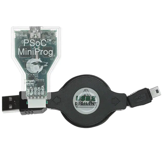
MiniProg1
Figure 3-8. MiniProg1 Details
3.15.1
Connect MiniProg1
The PSoC 1 device can be programmed using a MiniProg1 by connecting it to the ISSP header on
the board, as shown in Figure 3-9.
Figure 3-9. Connect MiniProg1
Red LED
ISSP Header
Note Ensure that the first pin (Vdd) of MiniProg1 is connected to the first pin (Vdd) of the ISSP programming header on the target board.
20
CY3217-MiniProg1 Kit Guide, Spec. # 001-66541 Rev. *A
�Using MiniProg1
3.15.2
Program with MiniProg1
Follow these steps to program using MiniProg1:
1. Connect the USB cable to the PC and MiniProg1.
2. Plug in the MiniProg1 to the ISSP header on the target board.
3. When USB is connected to the MiniProg1, the green LED glows in the MiniProg1.
4. Open PSoC Programmer (see Start PSoC Programmer on page 14 for details).
5. Click the File Load button and browse to the hex file location. Select the hex file and click Open.
6. Click Connect or double-click on the respective MiniProg under Port Selection to connect to the
MiniProg.
7. Click Program or press [F5] to initiate programming (see Program a Device on page 17 for
details).
8. The green LED on the MiniProg1 blinks to indicate the progress of programming.
9. After successful programming, the red LED on the MiniProg1 is powered off.
10.Select the Toggle Power button in PSoC Programmer to power the board via MiniProg1 and verify output.
Note When MiniProg1 cable is unplugged from PC during programming, programming fails, as
shown in Figure 3-10.
Figure 3-10. PSoC Programmer
CY3217-MiniProg1 Kit Guide, Spec. # 001-66541 Rev. *A
21
�Using MiniProg1
22
CY3217-MiniProg1 Kit Guide, Spec. # 001-66541 Rev. *A
�A.
A.1
Appendix
Programming Header
This section discusses the design consideration and component selection for the programming
header on the target board.
The 5-pin connector on MiniProg1 is configured as a single row with a 100-mil pitch. It is designed to
mate with a Molex model 22-23-2051 (straight) or 22-05-3051 (right angle) male header, with a key
tab. The signal assignment is shown in Figure A-1.
Figure A-1. Signal Assignment
MiniProg1 (End View)
Mating Header on Target Board
Figure A-2. Proposed Schematic for Mating Header (on target board)
CY3217-MiniProg1 Kit Guide, Spec. # 001-66541 Rev. *A
23
�See the respective PSoC 1 data sheet for pin SCLK and SDATA pin assignments.
Figure A-3. Proposed Header (on target board)
This is a five position, 2.54 mm (.100") pitch header from Molex Inc (Part No. 22-23-2051).
For details on the header, visit http://www.molex.com/molex/products/datasheet.jsp?part=active/
0022232051_PCB_HEADERS.xml&channel=Products.
24
CY3217-MiniProg1 Kit Guide, Spec. # 001-66541 Rev. *A
�


 工商网监
湘ICP备2023018690号
工商网监
湘ICP备2023018690号
