Please note that Cypress is an Infineon Technologies Company.
The document following this cover page is marked as “Cypress” document as this is the
company that originally developed the product. Please note that Infineon will continue
to offer the product to new and existing customers as part of the Infineon product
portfolio.
Continuity of document content
The fact that Infineon offers the following product as part of the Infineon product
portfolio does not lead to any changes to this document. Future revisions will occur
when appropriate, and any changes will be set out on the document history page.
Continuity of ordering part numbers
Infineon continues to support existing part numbers. Please continue to use the
ordering part numbers listed in the datasheet for ordering.
www.infineon.com
�CY8CKIT-031
PSoC® CapSense®
Expansion Board Kit Guide
Doc. # 001-66474 Rev. *H
Cypress Semiconductor
198 Champion Court
San Jose, CA 95134-1709
http://www.cypress.com
�Copyrights
Copyrights
© Cypress Semiconductor Corporation, 2011-2018. This document is the property of Cypress Semiconductor Corporation
and its subsidiaries, including Spansion LLC ("Cypress"). This document, including any software or firmware included or referenced in this document ("Software"), is owned by Cypress under the intellectual property laws and treaties of the United
States and other countries worldwide. Cypress reserves all rights under such laws and treaties and does not, except as specifically stated in this paragraph, grant any license under its patents, copyrights, trademarks, or other intellectual property
rights. If the Software is not accompanied by a license agreement and you do not otherwise have a written agreement with
Cypress governing the use of the Software, then Cypress hereby grants you a personal, non-exclusive, nontransferable
license (without the right to sublicense) (1) under its copyright rights in the Software (a) for Software provided in source code
form, to modify and reproduce the Software solely for use with Cypress hardware products, only internally within your organization, and (b) to distribute the Software in binary code form externally to end users (either directly or indirectly through resellers and distributors), solely for use on Cypress hardware product units, and (2) under those claims of Cypress's patents that
are infringed by the Software (as provided by Cypress, unmodified) to make, use, distribute, and import the Software solely
for use with Cypress hardware products. Any other use, reproduction, modification, translation, or compilation of the Software
is prohibited.
TO THE EXTENT PERMITTED BY APPLICABLE LAW, CYPRESS MAKES NO WARRANTY OF ANY KIND, EXPRESS OR
IMPLIED, WITH REGARD TO THIS DOCUMENT OR ANY SOFTWARE OR ACCOMPANYING HARDWARE, INCLUDING,
BUT NOT LIMITED TO, THE IMPLIED WARRANTIES OF MERCHANTABILITY AND FITNESS FOR A PARTICULAR PURPOSE. No computing device can be absolutely secure. Therefore, despite security measures implemented in Cypress hardware or software products, Cypress does not assume any liability arising out of any security breach, such as unauthorized
access to or use of a Cypress product. In addition, the products described in these materials may contain design defects or
errors known as errata which may cause the product to deviate from published specifications. To the extent permitted by
applicable law, Cypress reserves the right to make changes to this document without further notice.
Cypress does not assume any liability arising out of the application or use of any product or circuit described in this document.
Any information provided in this document, including any sample design information or programming code, is provided only
for reference purposes. It is the responsibility of the user of this document to properly design, program, and test the functionality and safety of any application made of this information and any resulting product. Cypress products are not designed,
intended, or authorized for use as critical components in systems designed or intended for the operation of weapons, weapons systems, nuclear installations, life-support devices or systems, other medical devices or systems (including resuscitation
equipment and surgical implants), pollution control or hazardous substances management, or other uses where the failure of
the device or system could cause personal injury, death, or property damage ("Unintended Uses"). A critical component is
any component of a device or system whose failure to perform can be reasonably expected to cause the failure of the device
or system, or to affect its safety or effectiveness. Cypress is not liable, in whole or in part, and you shall and hereby do release
Cypress from any claim, damage, or other liability arising from or related to all Unintended Uses of Cypress products. You
shall indemnify and hold Cypress harmless from and against all claims, costs, damages, and other liabilities, including claims
for personal injury or death, arising from or related to any Unintended Uses of Cypress products.
Cypress, the Cypress logo, Spansion, the Spansion logo, and combinations thereof, WICED, PSoC, CapSense, EZ-USB, FRAM, and Traveo are trademarks or registered trademarks of Cypress in the United States and other countries. For a more
complete list of Cypress trademarks, visit cypress.com. Other names and brands may be claimed as property of their respective owners.
CY8CKIT-031 PSoC® CapSense® Expansion Board Kit Guide, Doc. # 001-66474 Rev. *H
2
�Contents
Safety Information
1. Introduction
1.1
1.2
1.3
1.4
1.5
7
Kit Contents .................................................................................................................7
PSoC Creator ..............................................................................................................7
Getting Started.............................................................................................................8
Additional Resources ...................................................................................................8
1.4.1 Beginner Resources.........................................................................................8
1.4.2 Engineers Looking for More .............................................................................8
1.4.3 Learning from Peers.........................................................................................8
1.4.4 More Code Examples.......................................................................................8
Documentation Conventions......................................................................................10
2. Installation
2.1
2.2
2.3
5
11
CD Installation ...........................................................................................................11
Hardware ...................................................................................................................12
Software.....................................................................................................................12
3. Kit Operation
13
4. Code Examples
16
4.1
4.2
4.3
4.4
4.5
Migrating the projects to use with CY8CKIT-050 and CY8CKIT-010 ........................16
Code Example 1: BMM_USB ....................................................................................16
4.2.1 Project Description .........................................................................................16
4.2.2 Hardware Connections...................................................................................18
4.2.3 Verify Output ..................................................................................................18
Code Example 2: SLM_USB .....................................................................................19
4.3.1 Project Description .........................................................................................19
4.3.2 Hardware Connections...................................................................................19
4.3.3 Verify Output ..................................................................................................20
Code Example 3: BMM_I2C_Tuner ...........................................................................21
4.4.1 BMM_I2C_Tuning example (Without Tuning) ................................................21
4.4.2 BMM_I2C_Tuning (With Tuning) ....................................................................22
Code Example 4: SLM_I2C_Tuner ............................................................................28
4.5.1 SLM_I2C_Tuning example (Without Tuning) .................................................28
4.5.2 SLM_I2C_Tuning (With Tuning) .....................................................................29
CY8CKIT-031 PSoC® CapSense® Expansion Board Kit Guide, Doc. # 001-66474 Rev. *H
3
�Contents
A. Appendix
A.1
A.2
A.3
A.4
A.5
A.6
32
Schematic ..................................................................................................................32
Board Layout .............................................................................................................33
A.2.1 PDC-09801 Top Layer ..................................................................................33
A.2.2 PDC-09801 Bottom Layer .............................................................................33
Bill of Materials (BOM) ...............................................................................................34
Board Files.................................................................................................................34
Shielding Electrode ....................................................................................................34
Regulatory Compliance Information ..........................................................................34
Revision History
CY8CKIT-031 PSoC® CapSense® Expansion Board Kit Guide, Doc. # 001-66474 Rev. *H
35
4
�Safety Information
Regulatory Compliance
The CY8CKIT-031 is intended for use as a development platform for hardware or software in a
laboratory environment. The board is an open system design, which does not include a shielded
enclosure. This may cause interference to other electrical or electronic devices in close proximity.
In a domestic environment, this product may cause radio interference. In this case, the user may be
required to take adequate prevention measures. Also, the board should not be used near any
medical equipment or RF devices.
Attaching additional wiring to this product or modifying the product operation from the factory default
may affect its performance and cause interference with other apparatus in the immediate vicinity. If
such interference is detected, suitable mitigating measures should be taken.
The CY8CKIT-031 as shipped from the factory has been verified to meet with requirements of CE as
a Class A product.
The CY8CKIT-031 contains electrostatic discharge (ESD) sensitive
devices. Electrostatic charges readily accumulate on the human body
and any equipment, and can discharge without detection. Permanent
damage may occur on devices subjected to high-energy discharges.
Proper ESD precautions are recommended to avoid performance
degradation or loss of functionality. Store unused CY8CKIT-031
boards in the protective shipping package.
End-of-Life/Product Recycling
This end-of life for this kit is five years from the date of manufacture,
mentioned on the back of the box. Contact your nearest recycler for
information on how to disposition the kit.
CY8CKIT-031 PSoC® CapSense® Expansion Board Kit Guide, Doc. # 001-66474 Rev. *H
5
�Safety Information
General Safety Instructions
ESD Protection
ESD can damage boards and associated components. Cypress recommends that you perform
procedures only at an ESD workstation. If one is not available, use appropriate ESD protection by
wearing an antistatic wrist strap attached to chassis ground (any unpainted metal surface) on your
board when handling parts.
Handling Boards
CY8CKIT-031 boards are sensitive to ESD. Hold the board only by its edges. After removing the
board from its box, place it on a grounded, static free surface. Use a conductive foam pad if
available. Do not slide board over any surface.
CY8CKIT-031 PSoC® CapSense® Expansion Board Kit Guide, Doc. # 001-66474 Rev. *H
6
�1.
Introduction
Thank you for your interest in the CY8CKIT-031 PSoC® CapSense® Expansion Board Kit. The
PSoC CapSense Expansion Board Kit interfaces either of the CY3280 Universal CapSense Module
boards with the CY8CKIT-001 PSoC Development Kit, CY8CKIT-030 PSoC 3 Development Kit, or
CY8CKIT-050 PSoC 5LP Development Kit. This kit enables you to develop CapSense solutions with
the CY3280 Universal CapSense Module boards. The CapSense component in PSoC Creator™
allows you to develop CapSense solutions with ease. The code examples provided along with this kit
give sample solutions.
The PSoC CapSense Expansion Board is based on the PSoC 3 and PSoC 5LP device families.
These devices are based on Cypress’ Programmable System-on-Chip™ platform for 8-, 16-, and 32bit applications. PSoC 3/5LP combines precision analog and digital logic with a high-performance
CPU. With the PSoC, you can create the exact combination of peripherals and integrated proprietary
IP to meet your application needs.
1.1
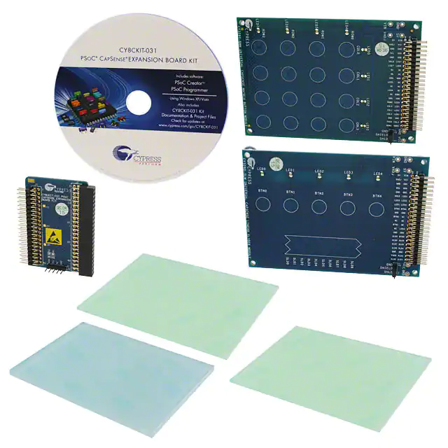
Kit Contents
The CY8CKIT-031 kit includes:
1.2
■
CY8CKIT-031 PSoC CapSense Expansion Board
■
CY3280-BMM Universal CapSense Matrix Button Module Kit
■
CY3280-SLM Universal CapSense Linear Slider Module Kit
■
Two 1.5-mm thick overlay and one 3-mm thick overlay
■
Quick Start Guide
■
Resource CD
PSoC Creator
Cypress' PSoC Creator software is a state-of-the-art, easy-to-use integrated development
environment (IDE) that introduces a hardware and software design environment based on classic
schematic entry and revolutionary embedded design methodology.
With PSoC Creator, you can:
■
Automatically place and route select components and integrate simple glue logic normally
located in discrete muxes.
■
Trade off hardware and software design considerations allowing you to focus on what matters
and getting to market faster.
PSoC Creator also enables you to tap into an entire tools ecosystem with integrated compiler tool
chains, RTOS solutions, and production programmers to support both PSoC 3, PSoC 4 and
PSoC 5LP.
CY8CKIT-031 PSoC® CapSense® Expansion Board Kit Guide, Doc. # 001-66474 Rev. *H
7
�Introduction
1.3
Getting Started
To get started, go to Kit Operation chapter on page 13 for a description of the kit operation. This
chapter explains how the CapSense expansion board kit connects to a development kit and CY3280
module boards. The Code Examples chapter on page 16 explains code examples provided with the
kit. The Appendix chapter on page 32 provides the schematics and bill of materials (BOM)
associated with the CapSense Expansion Board Kit.
1.4
Additional Resources
Visit http://www.cypress.com/go/training for additional learning resources in the form of datasheets,
technical reference manual, and application notes.
1.4.1
Beginner Resources
AN54181 - PSoC 3 - Getting Started with a PSoC 3 Design Project
AN77759 - Getting Started with PSoC 5LP
PSoC Creator Training
1.4.2
Engineers Looking for More
AN54460 - PSoC 3, PSoC 4, and PSoC 5LP Interrupts
AN52705 - PSoC 3 and PSoC 5LP - Getting Started with DMA
AN52701 - PSoC 3 and PSoC 5LP - Getting Started with Controller Area Network (CAN)
AN54439 - PSoC 3 and PSoC 5LP External Crystal Oscillators
AN52927 - PSoC 3 and PSoC 5LP - Segment LCD Direct Drive
Cypress continually strives to provide the best support. Click here to view a growing list of
application notes for PSoC 3, PSoC 4 and PSoC 5LP.
1.4.3
Learning from Peers
Cypress Developer Community Forums
1.4.4
More Code Examples
PSoC Creator provides several example projects that make code development fast and easy. To
access these example projects, click on Find Example Project… under the Example and Kits section in the Start Page of PSoC Creator or navigate to File > Open > Example Project….
CY8CKIT-031 PSoC® CapSense® Expansion Board Kit Guide, Doc. # 001-66474 Rev. *H
8
�Introduction
Figure 1-1. Find Example Project
The Find Example Project section has various filters that help you locate the most relevant project.
PSoC Creator provides several starter designs. These designs highlight features that are unique to
PSoC devices. They allow you to create a design with various components, instead of creating a
new empty design; code is also provided. To use a starter design for your project, navigate to File >
New > Project and select the design required.
Figure 1-2. New Project
CY8CKIT-031 PSoC® CapSense® Expansion Board Kit Guide, Doc. # 001-66474 Rev. *H
9
�Introduction
The starter designs and the example project contain a PDF within the project that explains the features of the project and its configuration.
Figure 1-3. Project PDF Location
Note The example projects and starter designs are designed for CY8CKIT-001 PSoC Development
Kit. However, these projects can be converted for use with CY8CKIT-030 PSoC 3 Development Kit
or CY8CKIT-050 PSoC 5LP Development Kit by following the procedure in the knowledge base article Migrating CY8CKIT-001 DVK project to CY8CKIT 030/ 050.
Apart from the example projects and starter designs that are available within PSoC Creator, Cypress
continuously strives to provide the best support. Click here to view a growing list of application notes
for PSoC 3 and PSoC 5LP.
1.5
Documentation Conventions
Table 1-1. Document Conventions for Guides
Convention
Usage
Courier New
Displays file locations, user entered text, and source code:
C:\ ...cd\icc\
Italics
Displays file names and reference documentation:
Read about the sourcefile.hex file in the PSoC Designer User Guide.
[Bracketed, Bold]
Displays keyboard commands in procedures:
[Enter] or [Ctrl] [C]
File > Open
Represents menu paths:
File > Open > New Project
Bold
Displays commands, menu paths, and icon names in procedures:
Click the File icon and then click Open.
Times New Roman
Displays an equation:
2+2=4
Text in gray boxes
Describes cautions or unique functionality of the product.
CY8CKIT-031 PSoC® CapSense® Expansion Board Kit Guide, Doc. # 001-66474 Rev. *H
10
�2.
2.1
Installation
CD Installation
To install the CY8CKIT-031 PSoC CapSense Expansion Board Kit software, insert the kit CD into the
CD drive of your computer. The CD is designed to auto-run and the PSoC CapSense Expansion
Board Kit menu appears.
Figure 2-1. Kit Menu
Note If auto-run does not execute, double-click cyautorun.exe on the root directory of the CD.
After the installation is complete, the kit contents are available in the following location:
:\PSoC CapSense EBK\\
CY8CKIT-031 PSoC® CapSense® Expansion Board Kit Guide, Doc. # 001-66474 Rev. *H
11
�Installation
The setup installs the following software:
■
PSoC Creator
■
PSoC Programmer
■
Kit Documentation
■
❐
Quick Start Guide
❐
Kit Guide
❐
Release Notes
Firmware
❐
■
Code Examples
Hardware files
❐
Schematic
❐
Layout
❐
BOM
Note The hardware files for CY8CKIT-031, CY3280-Matrix Button Module, and CY3280-Linear
Slider Module kits are installed in :\PSoC CapSense EBK\\
Hardware.
2.2
Hardware
WARNING Static discharges from the human body can easily reach very high voltages in the order
of kilo volts. This can damage the PSoC 3 or PSoC 5LP device on the development kit. Ensure that
any static is discharged before touching the hardware. Follow the below steps to avoid any
undesired behavior on the board:
2.3
■
Power off the development kit before making any connections
■
Connect the PSoC CapSense Expansion Board Kit to the development kit being used
■
Connect the CY3280-Universal CapSense Module Board to the PSoC CapSense Expansion
Board
■
Power the development kit
Software
When installing the PSoC CapSense Expansion Board Kit, the installer checks if the prerequisites,
PSoC Creator, PSoC Programmer, Windows Installer, .NET, and Keil complier, are installed in your
computer. If these applications are not installed, the installer installs them in your PC before installing
the kit. If Acrobat Reader application is not installed in your PC, then the installer provides the link to
install the same and this does not prevent kit installation. Note that Adobe reader is required to view
the kit documents.
CY8CKIT-031 PSoC® CapSense® Expansion Board Kit Guide, Doc. # 001-66474 Rev. *H
12
�3.
Kit Operation
The following figures show the CY8CKIT-031 PSoC CapSense Expansion Board Kit, CY3280
CapSense Matrix Button Module, and CY3280 CapSense Linear Slider Module.
Figure 3-1. CY8CKIT-031 PSoC CapSense Expansion Board Kit
2x20-Pin
Connector for
DVK Interface
2x22 Pin
Connector for
CapSense
Interface
1x5 Pin Connector for I2C Interface
Figure 3-2. CapSense Matrix Button Module
Figure 3-3. CapSense Linear Slider Module
The PSoC CapSense Expansion Board Kit connects to the development kit using a 2×20-pin
connector. It connects to the CY3280 Universal CapSense Module Boards using 2×22-pin
connector.
CY8CKIT-031 PSoC® CapSense® Expansion Board Kit Guide, Doc. # 001-66474 Rev. *H
13
�Kit Operation
Figure 3-4. PSoC CapSense Expansion Board Kit Interface with PSoC Development Kit and
Universal CapSense Matrix Button Module Kit
Note: The figure shows the Capsense Expansion board connections when PSoC 3 processor
module is used. The same connections need to be done when PSoC 5LP Processor module is
used
Figure 3-5. PSoC CapSense Expansion Board Kit Interface with PSoC 3 Development Kit and
Universal CapSense Matrix Button Module Kit
Note: The figure shows the Capsense Expansion board connections when PSoC 3 Development
Kit is used. The same connections need to be done when PSoC 5LP Development Kit is used.
2x20 Connector
2x22 Connector
CY8CKIT-031 PSoC® CapSense® Expansion Board Kit Guide, Doc. # 001-66474 Rev. *H
14
�Kit Operation
The 5-pin connector provides the I2C interface.
Figure 3-6. I2C Connector
MiniProg3 connection to
I2C header for
communication with GUI
Note The PSoC CapSense Expansion Board Kit can use only port A of the CY8CKIT-001 PSoC
Development Kit. Other ports - port A', port B, and port C cannot be used with this kit.
CY8CKIT-031 PSoC® CapSense® Expansion Board Kit Guide, Doc. # 001-66474 Rev. *H
15
�4.
Code Examples
Four code examples are provided with the kit.
■
Code Example 1: BMM_USB
■
Code Example 2: SLM_USB
■
Code Example 3: BMM_I2C_Tuner (works only with MiniProg3)
■
Code Example 4: SLM_I2C_Tuner (works only with MiniProg3)
The code examples work with the following development kits:
■
CY8CKIT-001 PSoC Development Kit (using PSoC 3 Processor module and PSoC 5LP
Processor module)
■
CY8CKIT-030 PSoC 3 Development Kit
■
CY8CKIT-050LP PSoC 5 Development Kit
The PSoC Development Kit (CY8CKIT-001) examples are named with the suffix _KIT-001;
the PSoC 3 Development Kit examples are named with the suffix _KIT-030. The code examples with
suffix _KIT-001 can be used to work with both CY8CKIT-009 (PSoC 3 processor module) and
CY8CKIT-010 (PSoC 5LP processor module). Similarly, code examples with suffix _KIT-030 can be
used to work with both CY8CKIT-030 and CY8CKIT-050 as well. See Migrating the projects to use
with CY8CKIT-050 and CY8CKIT-010 for more details. Use the appropriate examples according to
development kit being used.
All code examples are available in the directory :\PSoC CapSense EBK
\\Firmware.
4.1
Migrating the projects to use with CY8CKIT-050 and CY8CKIT-010
By default, the project works with PSoC 3. To use the project for PSoC 5LP, change the device to
CY8C5868AXI-LP035 (Project > Device selector). If CY8CKIT-001 project is being updated for use
with PSoC 5 processor module then apart from the changing the device, change the pin mapping of
CMOD pin from P2_7 to pin 15_5.
4.2
Code Example 1: BMM_USB
Note The code example requires an USB cable to be connected from the PC to the USB connector
on the board.
4.2.1
Project Description
This example shows the CapSense Matrix Button Module (BMM) interfacing with the development
kit (CY8CKIT-001, CY8CKIT-030, or CY8CKIT-050LP) through the PSoC CapSense Expansion
Board. The example demonstrates the CapSense button matrix operation. When any button is
touched, the corresponding row and column LEDs turn on. This example also shows the calculator
application in the PC with the CapSense BMM as a keypad.
CY8CKIT-031 PSoC® CapSense® Expansion Board Kit Guide, Doc. # 001-66474 Rev. *H
16
�Code Examples
The BMM module has four row sensors and four column sensors. Touching a button activates the
corresponding row and column sensors. The example uses the auto-tuning feature (i.e., the tuning
method is set to Auto (Smart-Sense) in the Capsense component), which sets all CapSense
parameters to best values automatically. The USBFS component is configured as a HID keyboard.
The buttons on the BMM are mapped to keys on the calculator as follows:
Table 4-1. Button - Key Mapping
Col 0
Col 1
Col 2
Col3
Row 0
0
1
2
3
Row 1
4
5
6
7
Row 2
8
9
.
=
Row 3
+
–
*
/
The code waits for the USB cable to be connected to the PC from the USB connecter on the board
(USB connector J2 on CY8CKIT-030/CY8CKIT-050LP and USB connector J9 on CY8CKIT-001).
The code proceeds to CapSense sensor scanning only if USB enumeration is successful. When the
USB enumeration is successful, the LED4 on CY8CKIT-030/050 and LED1 on CY8CKIT-001 (a
jumper wire connection to P1_6 is required) on board turns on.
The example is tested to work without any overlay. When an overlay of some thickness is used, the
Sensitivity parameter should be changed appropriately for Capsense to work. To configure the
Sensitivity parameter, double-click on the CapSense_CSD component. Click on the Scan Order
tab. Select the individual CapSense sensor and configure sensitivity as required.
The sensitivity parameter indicates the finger capacitance, which depends on the button area,
overlay thickness, and dielectric constant of overlay material.
Figure 4-1. Configuring ‘CapSense_CSD’
CY8CKIT-031 PSoC® CapSense® Expansion Board Kit Guide, Doc. # 001-66474 Rev. *H
17
�Code Examples
To use the overlay, remove the adhesive sticker and stick it onto the board in such a way that all the
CapSense buttons and sliders are covered. Ensure that no air gaps or bubbles get trapped in
between the board and overlay.
4.2.2
Hardware Connections
For the PSoC Development Kit (CY8CKIT-001)
■
Connect the CapSense Matrix Button Module to connector J2 of the PSoC CapSense Expansion
Board.
■
Connect J1 of the PSoC CapSense Expansion Board to port A of the development kit.
■
Connect J2 on the CapSense Matrix Button Module to short SHIELD and SHLD.
■
Connect the USB cable from J9 on the development kit to the PC USB port.
■
Connect P1[6] to LED1. This LED is named Enumerate_LED and indicates that USB enumeration is complete.
For the PSoC 3 or PSoC 5LP Development Kit
■
Connect the CapSense Matrix Button Module to connector J2 of the PSoC CapSense Expansion
Board.
■
Connect J1 of the PSoC CapSense Expansion Board to port D of the development kit.
■
Connect J2 on the CapSense Matrix Button Module to short SHIELD and SHLD.
■
Connect jumpers J10 and J11 to position 2 and 3 to use the board at 5 V.
■
Connect the USB cable from J2 on the development kit to the PC USB port.
■
Pin P6[3] is used for the Enumerate_LED, which is connected to LED4 on the board; therefore,
an explicit connection is not required.
■
Remove LCD from port P8. The LCD module adds parasitic capacitance and noise to CapSense
because it shares the same pins of port D that are used for CapSense.
■
If MiniProg3 is used, then disconnect it from J3 after programming. The programming port J3
shares the port D pins and adds noise on CapSense if MiniProg3 is present.
Note See Shielding Electrode on page 34 for more details.
4.2.3
Verify Output
Build and program the code example and reset the device. After device is reset, wait for
Enumerate_LED to turn on, indicating that the system is ready. Touch a button and see the
corresponding row and column LEDs turn on. Open the calculator application in the PC, touch any
button, the corresponding key is pressed on calculator (see Table 4-1). Perform different operations
on the calculator using CapSense touch buttons.
Figure 4-2. CapSense Matrix Button Module Project
CY8CKIT-031 PSoC® CapSense® Expansion Board Kit Guide, Doc. # 001-66474 Rev. *H
18
�Code Examples
4.3
Code Example 2: SLM_USB
Note The code example requires an USB cable to be connected from the PC to the USB connector
on the board.
4.3.1
Project Description
This example shows the CapSense Linear Slider Module (SLM) interfacing with the development kit
(CY8CKIT-001, CY8CKIT-030, or CY8CKIT-050LP) through the PSoC CapSense Expansion Board.
The example demonstrates the CapSense slider and button combination. The SLM module has 10
element slider and five buttons. The module also has five LEDs. Touch a button on the module to
turn on the corresponding LED; placing a finger on the slider, turns on the LED nearest to the finger
position. The example also shows a media player application in the PC with buttons and slider on the
CapSense SLM as media control buttons.
The project uses the auto-tuning feature (i.e., the tuning method is set to Auto (Smart-Sense) in the
Capsense component), which sets all CapSense parameters to the best values automatically. The
USBFS user module is configured as a HID keyboard. The buttons and slider on the SLM are used
as controls for the media player as follows.
BTN0 Play/Pause
BTN1 Stop
BTN2 Mute/UnMute
BTN3 Next Track
BTN4 Previous Track
Slider Left/Right - System Volume UP/DOWN
The code waits for the USB cable to be connected to the PC from the USB connecter on the board
(USB connector J2 on CY8CKIT-030/CY8CKIT-050LP and USB connector J9 on CY8CKIT-001).
The code proceeds to CapSense sensor scanning only if the USB enumeration is successful. When
the USB enumeration is successful, the LED4 on CY8CKIT-030/050 and LED1 on CY8CKIT-001 (a
jumper wire connection to P1_6 is required) on the board turns on.
The example is tested to work without any overlay. When overlay is used, the sensitivity parameter
should be changed appropriately for Capsense to work. To configure the Sensitivity parameter,
double-click on the CapSense_CSD component. Click on the Scan Order tab. Select the individual
CapSense sensor and configure sensitivity as required.
4.3.2
Hardware Connections
For the PSoC Development Kit (CY8CKIT-001)
■
Connect the CapSense Linear Slider Module to connector J2 of the PSoC CapSense Expansion
Board.
■
Connect J1 of the PSoC CapSense Expansion Board Kit to port A of the development kit.
■
Connect J2 on the CapSense Linear Slider Module to short SHIELD and SHLD.
■
Connect the USB cable from J9 on the development kit to the PC USB port.
■
Connect P1[6] to LED1. This LED is named Enumerate_LED and indicates that USB enumeration is complete.
For the PSoC 3 or PSoC 5LP Development Kit
■
Connect the CapSense Linear Slider Module to connector J2 of the PSoC CapSense Expansion
Board.
CY8CKIT-031 PSoC® CapSense® Expansion Board Kit Guide, Doc. # 001-66474 Rev. *H
19
�Code Examples
■
Connect J1 of the PSoC CapSense Expansion Board Kit to the port D of the development kit.
■
Connect J2 on the CapSense Linear Slider Module to short SHIELD and SHLD.
■
Connect jumpers J10 and J11 to position 1 and 2 to use the board at 3.3 V.
■
Connect the USB cable from J2 on the development kit to the PC USB port.
■
Pin P6[3] is used for Enumerate_LED, which is connected to LED4 on the board; therefore, an
explicit connection is not required.
■
Remove LCD from port P8. The LCD module adds parasitic capacitance and noise to CapSense
because it shares the same pins of port D that are used for CapSense.
■
If MiniProg3 is used, then disconnect it from J3 after programming. The programming port J3
shares the port D pins and adds noise on CapSense if MiniProg3 is present.
Note See Shielding Electrode on page 34 for more details.
4.3.3
Verify Output
Build and program the code example and reset the device. After the device is reset, wait for the
Enumerate_LED to turn on, indicating that the system is ready. Touch a button and see the
corresponding LED turn on. Place a finger on the slider and see the nearest LED turn on. Open any
media player application on the PC. Perform different operations such as Play/Pause, Stop,
Mute/Unmute, Next, Previous, and System Volume Control using CapSense Linear Slider Module
touch controls.
Figure 4-3. CapSense Linear Slider Module Project
CY8CKIT-031 PSoC® CapSense® Expansion Board Kit Guide, Doc. # 001-66474 Rev. *H
20
�Code Examples
4.4
Code Example 3: BMM_I2C_Tuner
This code example can be executed in 2 ways: With Capsense Tuning (requires I2C interface using
MiniProg3) and Without Capsense Tuning (no additional requirements) i.e., the same project can be
used to demonstrate the capsense functionality as well as Capsense tuning using Tuner Helper GUI
in PSoC Creator. This is done by commenting/uncommenting the line #define ENABLE_TUNING in
the main.c file of the code example. PSoC creator does not compile the code under #ifdef (if defined)
statement when #define statement is commented (/*…… */ or //). Similarly, when the #define
statement is removed from comments, the code required for working with Tuner GUI gets compiled.
By default, the project is set to work without Capsense tuning by commenting the #define.
4.4.1
BMM_I2C_Tuning example (Without Tuning)
4.4.1.1
Project Description
This code example provides a platform to build CapSense-based projects. This project
demonstrates the use of CapSense Matrix Buttons using Capsense_CSD component in PSoC
Creator.
When a Capsense button is touched, the leds corresponding to the Row and Column gets turned
ON. The project uses the auto-tuning feature, which sets all CapSense parameters to the best
values automatically. The parameter settings can be monitored in the GUI but cannot be altered
because they are set by auto-tuning.
4.4.1.2
Hardware Connections
■
Connect the CapSense Matrix Button Module to connector J2 of the PSoC CapSense Expansion
Board.
■
For the PSoC Development Kit, connect J1 of the PSoC CapSense Expansion Board Kit to port A
of the development kit.
■
For the PSoC 3/5LP Development Kit, connect J1 of the PSoC CapSense Expansion Board Kit to
port D of the development kit. Remove LCD from port P8. LCD module adds parasitic
capacitance and noise to CapSense because it shares the same pins of port D that are used for
CapSense.
■
Connect jumper J2 on the CapSense Matrix Button Slider Module to short SHIELD and SHLD.
■
Build and program the code example and reset the device.
Note See Shielding Electrode on page 31 for more details.
4.4.1.3
Verify Output
Touch any button and observe that corresponding row and column LED turns ON.
Figure 4-4. CapSense Matrix Button Module Project
CY8CKIT-031 PSoC® CapSense® Expansion Board Kit Guide, Doc. # 001-66474 Rev. *H
21
�Code Examples
Note To evaluate the Capsense tuning part of the code example, a MiniProg3 is required. It does
not work without MiniProg3 because the code waits forever in the main loop if I2C communication is
not set up. You can buy MiniProg3 through this link http:www.cypress.com/go/CY8CKIT-002.
4.4.2
BMM_I2C_Tuning (With Tuning)
4.4.2.1
Project Description
This code example shows the CapSense Matrix Button Module (BMM) with "Tuner" for monitoring of
CapSense outputs. The CapSense outputs such as Rawcounts, Baseline, and Signal (Difference
count) can be monitored on the "Tuner" GUI. The project uses the auto-tuning feature, which sets all
CapSense parameters to the best values automatically. The parameter settings can be monitored in
the GUI but cannot be altered because they are set by auto-tuning. In the manual tuning method,
parameter settings can be changed in the GUI and the resulting output can be seen.
The example also makes use of LEDs on the CapSense BMM board. Touching a button turns on the
corresponding LED. The code uses tuner APIs. The tuner API CapSense_TunerComm() is used in
main loop to scan sensors, which also sends the CapSense variables RawCounts, Baseline, and
Difference counts (Signal) to the PC GUI through I2C communication.
The Sensitivity parameter in the CapSense_CSD component configuration is set to ‘4’ and the
example is tested to work without any overlay. When an overlay of some thickness is used, the
sensitivity parameter should be changed to ‘1’, as shown in Figure 4-1 on page 17. To configure the
Sensitivity parameter, double-click on the CapSense_CSD component. Click on the Scan Order
tab. Select the individual CapSense sensor and configure the sensitivity as required.
4.4.2.2
Hardware Connections
■
Connect the CapSense Matrix Button Module to connector J2 of the PSoC CapSense Expansion
Board.
■
For the PSoC Development Kit (CY8CKIT-001), connect J1 of the PSoC CapSense Expansion
Board Kit to port A of the development kit.
■
For the PSoC 3 or PSoC 5LP Development Kit, connect J1 of the PSoC CapSense Expansion
Board Kit to port D of the development kit. Remove LCD from port P8. LCD module adds
parasitic capacitance and noise to CapSense because it shares the same pins of port D that are
used for CapSense.
■
Connect jumper J2 on the CapSense Matrix Button Slider Module to short SHIELD and SHLD.
■
Build and program the code example and reset the device.
■
If MiniProg3 is used, then disconnect it from the programming port and PC. The MiniProg3 is
used for I2C communication. Connect MiniProg3 to the J3 header on the PSoC CapSense
Expansion Board Kit. Make sure that I2C pins SDA, SCL, and GND on the MiniProg3 are
mapped to the corresponding I2C pins on the kit; see Figure 3-6 on page 15 for the connections.
Note that when MiniProg3 is used for both I2C and programming, the MiniProg3 should be disconnected from PC every time the connection is changed.
Note See Shielding Electrode on page 34 for more details.
CY8CKIT-031 PSoC® CapSense® Expansion Board Kit Guide, Doc. # 001-66474 Rev. *H
22
�Code Examples
4.4.2.3
Launching Tuner GUI
The Tuner GUI from PSoC Creator should be up and running for the code example to work. To
launch the GUI, follow these steps:
1. Go to the project’s TopDesign.cysch file.
2. To open the tuner, right-click on the CapSense_CSD component in PSoC Creator and click on
Launch Tuner.
CY8CKIT-031 PSoC® CapSense® Expansion Board Kit Guide, Doc. # 001-66474 Rev. *H
23
�Code Examples
3. Click on the Configuration button to open the configuration window.
4. Set the I2C communication parameters same as that set in the EZI2C component.
5. Select any option for the I2C Voltage other than External. The external supply pin on the
MiniProg3 VTARG connects to NC on the CY8CKIT-031 board. Therefore, the external supply
option does not work with the CY8CKIT-030 and CY8CKIT-050LP.
6. Click OK to apply the settings.
CY8CKIT-031 PSoC® CapSense® Expansion Board Kit Guide, Doc. # 001-66474 Rev. *H
24
�Code Examples
4.4.2.4
Verify Output
1. To start the scanning and communication process, click Start.
2. Open the Graphing tab; it shows different CapSense results RawCounts, Baseline, and
Difference count (signal) for each sensor.
3. Select the sensor parameter to observe, as shown in Figure 4-5. See the graph for different variables.
4. Touch the button and observe the increase in counts.
Note: The Tuner GUI does not show correct output if multiple buttons are touched.
CY8CKIT-031 PSoC® CapSense® Expansion Board Kit Guide, Doc. # 001-66474 Rev. *H
25
�Code Examples
Figure 4-5. Graphs for Matrix Button Module Project
Touch any button and observe the corresponding LED turned on. Figure 4-5 shows the monitoring of RawCounts, Baseline, and Difference count (signal) for the Column 0 sensor.
5. Open the Tuning tab and select a sensor row or column. Different CapSense parameters are
shown on the bottom-right. Because auto-tuning is used in this project, you cannot edit the settings. Auto-tuning automatically sets all the parameters. The GUI is used to monitor the
CapSense variables RawCounts, Baseline, and Signal for all sensors. Touch the button 0 (Row 0
Col 0) to see the sensor response in the tuner window, as shown in Figure 4-6. Also, observe
that the corresponding row and col LED on the module board turns on.
CY8CKIT-031 PSoC® CapSense® Expansion Board Kit Guide, Doc. # 001-66474 Rev. *H
26
�Code Examples
Figure 4-6. Tuner Window
Figure 4-7. Tuner Project
CY8CKIT-031 PSoC® CapSense® Expansion Board Kit Guide, Doc. # 001-66474 Rev. *H
27
�Code Examples
4.5
Code Example 4: SLM_I2C_Tuner
This code example can be executed in 2 ways: With Capsense Tuning (requires I2C interface using
MiniProg3) and Without Capsense Tuning (no additional requirements) i.e., the same project can be
used to demonstrate the capsense functionality as well as Capsense tuning using Tuner Helper GUI
in PSoC Creator. This is done by commenting/uncommenting the line #define ENABLE_TUNING in
the main.c file of the code example. PSoC creator does not compile the code under #ifdef (if defined)
statement when #define statement is commented (/*…… */ or //). Similarly, when the #define
statement is removed from comments, the code required for working with Tuner GUI gets compiled.
By default, the project is set to work without Capsense tuning by commenting the #define.
4.5.1
SLM_I2C_Tuning example (Without Tuning)
4.5.1.1
Project Description
This code example provides a platform to build CapSense-based projects. This project
demonstrates the use of CapSense Slider Module using Capsense_CSD component in PSoC
Creator.
When a Capsense button is touched, the corresponding LED is turned ON. If a finger is placed on
the slider, the nearest LED turns ON and the finger position is displayed on LCD. The project uses
the auto-tuning feature, which sets all CapSense parameters to the best values automatically. The
parameter settings can be monitored in the GUI but cannot be altered because they are set by autotuning.
4.5.1.2
Hardware Connections
■
Connect the CapSense Linear Slider Module to connector J2 of the PSoC CapSense Expansion
Board.
■
For the PSoC Development Kit, connect J1 of the PSoC CapSense Expansion Board Kit to port A
of the development kit.
■
For the PSoC 3/5LP Development Kit, connect J1 of the PSoC CapSense Expansion Board Kit to
port E of the development kit.
■
Connect the LCD to connector P8.
■
Connect jumper J2 on the CapSense Matrix Button Slider Module to short SHIELD and SHLD.
■
Remove the SAR Bypass jumpers SAR1_BYP (J43) and SAR2_BYP (J44).
■
Build and program the code example and reset the device.
Note See Shielding Electrode on page 31 for more details.
4.5.1.3
Verify Output
Touch any button and observe the corresponding LED turn on. Place a finger on the slider; the
nearest LED turns on and the finger position is displayed on the LCD.
CY8CKIT-031 PSoC® CapSense® Expansion Board Kit Guide, Doc. # 001-66474 Rev. *H
28
�Code Examples
Figure 4-8. CapSense Linear Slider Module Project
Notes
■
To evaluate the Capsense tuning part of the code example, a MiniProg3 is required. It does not
work without MiniProg3 because the code waits forever in the main loop if I2C communication is
not set up. You can buy MiniProg3 at http://www.cypress.com/go/CY8CKIT-002.
■
The example uses Port E for the PSoC 3 and PSoC 5LP development kits and includes an LCD
to display the slider position.
4.5.2
SLM_I2C_Tuning (With Tuning)
4.5.2.1
Project Description
This code example shows the CapSense Linear Slider Module (SLM) with "Tuner" for monitoring
CapSense outputs. The CapSense outputs such as Rawcounts, Baseline, and Signal (Difference
count) can be monitored on the "Tuner" GUI. The project uses the auto-tuning feature, which sets all
CapSense parameters to best values automatically.
The project includes a character LCD for displaying the slider position. The slider position is
displayed as a horizontal bar graph on the character LCD. The LEDs on the CapSense SLM board
turn on when the corresponding button is touched. When a slider is touched, the nearest LED turns
on. The code uses tuner APIs. The tuner API CapSense_TunerComm() is used in the main loop to
scan sensors, which also sends the CapSense variables RawCounts, Baseline, and Difference
counts (Signal) to the PC GUI through I2C communication.
The example is tested to work without any overlay. When an overlay is used, the sensitivity
parameter should be changed appropriately for the Capsense to work. To configure the Sensitivity
parameter, double-click on the CapSense_CSD component. Click on the Scan Order tab. Select
the individual CapSense sensor and configure the sensitivity as required.
4.5.2.2
Hardware Connections
Note The example uses Port E for the PSoC 3 and PSoC 5LP development kits instead of port D as
with the other examples. This is to accommodate the LCD, which uses the same pins of port D as
the CapSense.
■
Connect the CapSense Linear Slider Module to connector J2 of the PSoC CapSense Expansion
Board.
■
Connect jumper J2 on the CapSense Linear Slider Module to short SHIELD and SHLD.
■
For the PSoC Development Kit
❐
Connect J1 of the PSoC CapSense Expansion Board Kit to port A of the development kit.
❐
Connect the LCD to P18 and place jumper J12 in the ON position to power on the LCD.
CY8CKIT-031 PSoC® CapSense® Expansion Board Kit Guide, Doc. # 001-66474 Rev. *H
29
�Code Examples
■
For the PSoC 3 or PSoC 5LP Development Kit
❐
Connect J1 of the PSoC CapSense Expansion Board Kit to port E of the development kit.
❐
Connect the LCD to connector P8.
■
Remove the SAR Bypass jumpers SAR1_BYP (J43) and SAR2_BYP (J44).
■
Build and program the board. Reset the device.
■
If MiniProg3 is used, disconnect it from the programming port and PC. The MiniProg3 is used for
I2C communication. Connect the MiniProg3 to the J3 header1 on the PSoC CapSense
Expansion Board Kit. Make sure that I2C pins SDA, SCL, and GND on the MiniProg3 are
mapped to the corresponding I2C pins on the kit; see Figure 3-6 on page 15 for the connections.
Note that when MiniProg3 is used for both I2C and programming, the MiniProg3 should be
disconnected from the PC every time a connection is changed.
Note See Shielding Electrode on page 34 for more details.
4.5.2.3
Launching Tuner GUI
See Launching Tuner GUI on page 23 for details.
4.5.2.4
Verify Output
Monitor the parameter settings and waveforms for different CapSense sensors. Touch any button
and observe the corresponding LED turn on. Place a finger on the slider; the nearest LED turns on
and the finger position is displayed on the LCD.
Figure 4-9. LCD Showing Slider Position
1. Please note the orientation of MiniProg3 while connecting on the board.
CY8CKIT-031 PSoC® CapSense® Expansion Board Kit Guide, Doc. # 001-66474 Rev. *H
30
�Code Examples
Figure 4-10 shows the monitoring of RawCounts, Baseline, and Difference count (signal) for the
Column 0 sensor.
Figure 4-10. Graphs for CapSense Linear Slider Module Project
Figure 4-11. Tuner Window
Note The CY8CKIT-001 PSoC Development Kit gives lesser SNR performance. The kit is not
designed to give optimal CapSense performance. Only 1.5 mm overlay should be used with the
PSoC Development Kit.
CY8CKIT-031 PSoC® CapSense® Expansion Board Kit Guide, Doc. # 001-66474 Rev. *H
31
�A.
A.1
Appendix
Schematic
J2
J1
GPIO1
GPIO3
GPIO5
GPIO7
J4
1
1
GPIO9
GPIO11
GPIO13
GPIO15
NO LOAD
J5
1
1
GPIO17
GPIO19
GPIO21
NO LOAD
J6
1
NO LOAD
1
SCL SCL
VADJ
V5.0
2
4
6
8
10
12
14
16
18
20
22
24
26
28
30
32
34
36
38
40
2
4
6
8
10
12
14
16
18
20
22
24
26
28
30
32
34
36
38
40
1
3
5
7
9
11
13
15
17
19
21
23
25
27
29
31
33
35
37
39
1
3
5
7
9
11
13
15
17
19
21
23
25
27
29
31
33
35
37
39
GPIO2
GPIO4
GPIO2
GPIO4
GPIO6
GPIO8
GPIO6
GPIO8
GPIO10
GPIO12
GPIO10
GPIO12
GPIO14
GPIO16
GPIO14
GPIO16
GPIO18
GPIO20
GPIO22
GPIO24
GPIO17
GPIO19
GPIO21
GPIO24
GPIO23
SDA SDA
V3.3
SDA
V3.3
Vin
VIN
V3.3
VIN
20x2_RA_Recptacle
1
3
5
7
9
11
13
15
17
19
21
23
25
27
29
31
33
35
SDA 37
39
41
43
1
3
5
7
9
11
13
15
17
19
21
23
25
27
29
31
33
35
37
39
41
43
2
4
6
8
10
12
14
16
18
20
22
24
26
28
30
32
34
36
38
40
42
44
2
4
6
8
10
12
14
16
18
20
22
24
26
28
30
32
34
36
38
40
42
44
GPIO1
GPIO3
GPIO5
GPIO7
GPIO9
GPIO11
GPIO13
GPIO15
GPIO18
GPIO20
GPIO22
GPIO23
SCL
SCL Vadj
V5.0
VADJ
V5.0
22x2_RA_Recptacle
From Expansion Connector of DVK
To CapSense Connector
J3
SCL
SDA
R1 0E
R2 0E
1
2
3
4
5
1
2
3
4
5
5 PIN HDR
I2USB Connector
CY8CKIT-031 PSoC® CapSense® Expansion Board Kit Guide, Doc. # 001-66474 Rev. *H
32
�Appendix
A.2
Board Layout
A.2.1
PDC-09801 Top Layer
A.2.2
PDC-09801 Bottom Layer
CY8CKIT-031 PSoC® CapSense® Expansion Board Kit Guide, Doc. # 001-66474 Rev. *H
33
�Appendix
A.3
Bill of Materials (BOM)
Item Qty. Reference
Value
Description
Manufacturer
Mfr Part Number
PCB
Cypress
PDC-09801 Rev**
Sullins Electronics
Corp.
PBC20DBAN
Sullins Electronics
Corp.
PPPC222LJBN-RC
1
1
J1
40 Pin Header
CONN HEADER .100 DUAL R/A
40POS
2
1
J2
44 Pin Header
CONN FMALE 44POS DL .1" R/A
GOLD
3
1
J3
5 Pin Header
CONN HEADER VERT 5POS .100 Molex/Waldom
TIN
Electronics
22-28-4050
4
2
R1, R2
Zero
RES 0.0 OHM 1/10W 5% 0805
SMD
Panasonic-ECG
ERJ-6GEY0R00V
Richco Plastic Co
RBS-3R
Install on the bttom of the PCB as close to the corners as possible
5
A.4
2
N/A
BUMPER
BUMPER CLEAR .500X.23"
SQUARE
Board Files
The board files for the CY3280 Matrix Button Module and CY3280 Linear Slider Module are available at :\PSoC CapSense EBK\\Hardware.
A.5
Shielding Electrode
Some applications require reliable operation in the presence of water films or droplets. White goods,
automotive applications, various industrial applications, and others need capacitive sensors that do
not provide false triggering because of water, ice, and humidity changes. In this case, a separate
shielding electrode can be used. This electrode is located behind or outside the sensing electrode.
When water films are located on the device insulation overlay surface, the coupling between the
shielding and sensing electrodes is increased. The shielding electrode allows you to reduce the
influence of parasitic capacitance, which gives you more dynamic range for processing sense capacitance changes.
In some applications, it is useful to select the shielding electrode signal and its placement relative to
the sensing electrode such that increasing the coupling between these electrodes causes the opposite of the touch change of the sensing electrode capacitance measurement. This simplifies the high
level software API work. The CSD User Module supports separate output for the shielding electrode.
A.6
Regulatory Compliance Information
CY8CKIT-031 has been tested and verified to comply with the following electromagnetic compatibility (EMC) regulations.
■
CISPR 22 - Emissions
■
EN 55022 Class A - Immunity (Europe)
CY8CKIT-031 PSoC® CapSense® Expansion Board Kit Guide, Doc. # 001-66474 Rev. *H
34
�Revision History
Document Revision History
Document Title: CY8CKIT-031 PSoC® CapSense® Expansion Board Kit Guide
Document Number: 001-66474
Revision
ECN#
Issue Date
Origin of
Change
Description of Change
**
3191556
03/09/2011
PVKV
Initial version of kit guide.
*A
3210076
03/30/2011
PVKV
Added notes in Code Examples chapter on page 16.
*B
3290010
06/22/2011
SSUT
Updated “Verify Output” on page 25.
*C
3467134
12/16/2011
SASH
Updated PSoC Creator version.
*D
3596461
04/23/2012
SASH
Updated “Additional Resources” on page 8.
*E
3742717
09/13/2012
SASH
Updated the images in Code Examples chapter on page 16.
Added Safety Information chapter on page 5.
“Shielding Electrode” on page 34, and “Regulatory Compliance Information” on page 34.
Updated Introduction chapter on page 7:
Updated description.
Updated “PSoC Creator” on page 7:
Updated description.
Updated “Additional Resources” on page 8:
Updated “Beginner Resources” on page 8:
Added “AN77759 - Getting Started with PSoC 5LP” in the list.
Updated “Engineers Looking for More” on page 8:
Updated titles of all application notes.
Added “More Code Examples” on page 8.
*F
4194658
11/19/2013
SASH
Updated Installation chapter on page 11:
Updated “CD Installation” on page 11:
Updated Figure 2-1.
Updated “Hardware” on page 12:
Updated description.
Updated “Software” on page 12:
Updated description.
Updated Kit Operation chapter on page 13:
Added Note for Figure 3-4 on page 14.
Added Note for Figure 3-5 on page 14.
CY8CKIT-031 PSoC® CapSense® Expansion Board Kit Guide, Doc. # 001-66474 Rev. *H
35
�Revision History
Document Title: CY8CKIT-031 PSoC® CapSense® Expansion Board Kit Guide
Document Number: 001-66474
Revision
ECN#
Issue Date
Origin of
Change
Description of Change
Updated Code Examples chapter on page 16:
Removed “Code Example 1: BMM_LED”.
Added “Migrating the projects to use with CY8CKIT-050 and CY8CKIT-010” on page 16.
Updated “Code Example 1: BMM_USB” on page 16.
Updated “Project Description” on page 16:
Updated description.
Added Figure 4-1 on page 17.
Updated “Hardware Connections” on page 18:
Updated description.
Removed “Code Example 3: SLM_LED”.
Updated “Code Example 2: SLM_USB” on page 19:
Updated “Project Description” on page 19:
Updated description.
Updated “Hardware Connections” on page 19:
Updated description.
Updated “Verify Output” on page 20:
Updated description.
Updated “Code Example 3: BMM_I2C_Tuner” on page 21:
Added description.
*F (Cont.)
4194658
11/19/2013
SASH
Added “BMM_I2C_Tuning example (Without Tuning)” on page 21.
Updated “BMM_I2C_Tuning (With Tuning)” on page 22:
Updated “Hardware Connections” on page 22:
Updated description.
Updated “Launching Tuner GUI” on page 23:
Updated screenshots for step 1, step 2 and step 3.
Updated “Verify Output” on page 25:
Added a note below step 4.
Updated screenshots for step 1, step 4 and step 5.
Updated “Code Example 4: SLM_I2C_Tuner” on page 28:
Added description.
Added “SLM_I2C_Tuning example (Without Tuning)” on page 28.
Updated “SLM_I2C_Tuning (With Tuning)” on page 29:
Updated “Project Description” on page 29:
Updated description.
Updated “Hardware Connections” on page 29:
Updated description.
Updated “Verify Output” on page 30:
Updated Figure 4-10, Figure 4-11.
Updated to new template.
*G
4700103
03/25/2015
SASH
*H
6120701
04/03/2018
RKAD
No technical updates.
Completing Sunset Review.
Updated to new template.
Completing Sunset Review.
CY8CKIT-031 PSoC® CapSense® Expansion Board Kit Guide, Doc. # 001-66474 Rev. *H
36
�