Please note that Cypress is an Infineon Technologies Company.
The document following this cover page is marked as “Cypress” document as this is the
company that originally developed the product. Please note that Infineon will continue
to offer the product to new and existing customers as part of the Infineon product
portfolio.
Continuity of document content
The fact that Infineon offers the following product as part of the Infineon product
portfolio does not lead to any changes to this document. Future revisions will occur
when appropriate, and any changes will be set out on the document history page.
Continuity of ordering part numbers
Infineon continues to support existing part numbers. Please continue to use the
ordering part numbers listed in the datasheet for ordering.
www.infineon.com
�S70FS01GS
1-Gb (128 MB), 1.8 V FS-S Flash
Features
■
SPI with Multi-I/O
❐ SPI Clock polarity and phase modes 0 and 3
❐ DDR
❐ Extended Addressing: 24- or 32-bit address options
❐ Serial Command subset and footprint compatible with
S25FL1-K, S25FL-P, and S25FL-S SPI families
❐ Multi I/O Command subset and footprint compatible with
S25FL-P, S25FL1-K, and S25FL-S SPI families
■
Read
❐ Commands: Normal, Fast, Dual I/O, Quad I/O, DDR Quad I/O
❐ Modes: Burst Wrap, Quad Peripheral Interface (QPI)
❐ Serial Flash Discoverable Parameters (SFDP) and Common
Flash Interface (CFI), for configuration information.
■
■
Program
❐ 256 or 512 Bytes Page Programming buffer
❐ Program suspend and resume
❐ Automatic Error Correcting Code (ECC) – internal hardware
ECC with single bit error correction
Erase
❐ Hybrid sector option
• Physical set of eight 4 KB sectors and one 224 KB sector
at the top or bottom of address space with all remaining
sectors of 256 KB
❐ Uniform sector option
• Physical uniform 256 KB blocks
❐ Erase suspend and resume
❐ Erase status evaluation
❐ 100,000 Program-Erase Cycles on any sector, minimum
❐ 20 year data retention, minimum
Cypress Semiconductor Corporation
Document Number: 002-03833 Rev. *E
•
■
Security Features
❐ OTP array of 1024 Bytes
❐ Block Protection:
• Status Register bits to control protection against program
or erase of a contiguous range of sectors.
• Hardware and software control options
❐ Advanced Sector Protection (ASP)
• Individual sector protection controlled by boot code or
password
• Option for password control of read access
■
Technology
❐ Cypress 65 nm MirrorBit Technology with Eclipse Architecture
■
Single Supply Voltage with CMOS I/O
❐ 1.7V to 2.0V
■
Temperature Range
❐ Industrial (40 °C to +85 °C)
❐ Industrial Plus (40 °C to +105 °C)
❐ Automotive, AEC-Q100 Grade 3 (40 °C to +85 °C)
❐ Automotive, AEC-Q100 Grade 2 (40 °C to +105 °C)
❐ Automotive, AEC-Q100 Grade 1 (40 °C to +125 °C)
■
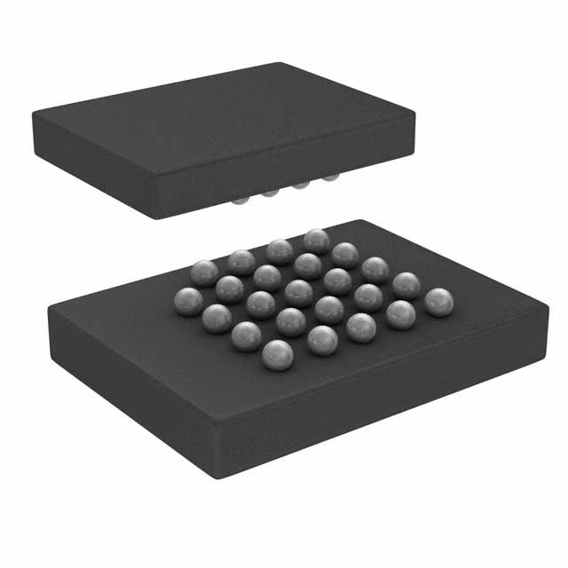
Packages (all Pb-free)
❐ 16-lead SOIC 300 mil
❐ BGA-24 6 8 mm
• 5 5 ball footprint
198 Champion Court
•
San Jose, CA 95134-1709
•
408-943-2600
Revised December 14, 2018
�S70FS01GS
Logic Block Diagram
S70FS01GS Device
CS#
SRAM
SCK
X Decoders
S25FS512S Die 1
MirrorBit Array
SI/IO0
Y Decoders
I/O
SO/IO1
Data Latch
Control
Logic
WP#/IO2
RESET#/IO3
Data Path
SRAM
X Decoders
S25FS512S Die 2
MirrorBit Array
Y Decoders
I/O
Data Latch
Control
Logic
Data Path
Document Number: 002-03833 Rev. *E
Page 2 of 141
�S70FS01GS
Performance Summary
Maximum Read Rates
Command
Clock Rate (MHz)
MBps
50
6.25
Fast Read
133
16.5
Dual Read
133
33
Quad Read
133
66
DDR Quad I/O Read
80
80
Read
Typical Program and Erase Rates
Operation
KBps
Page Programming (256-bytes page buffer)
712
Page Programming (512-bytes page buffer)
1080
4-KB Physical Sector Erase (Hybrid Sector Option)
28
256-KB Sector Erase (Uniform Logical Sector Option)
250
Typical Current Consumption, 40°C to +85°C
Operation
Current (mA)
Serial Read 50 MHz
10
Serial Read 133 MHz
20
Quad Read 133 MHz
60
Quad DDR Read 80 MHz
70
Program
60
Erase
60
Standby
0.07
Deep Power Down (DPD)
0.006
Document Number: 002-03833 Rev. *E
Page 3 of 141
�S70FS01GS
Contents
1.
1.1
1.2
1.3
1.4
Overview .......................................................................
General Description .......................................................
Migration Notes..............................................................
Glossary.........................................................................
Other Resources............................................................
2.
2.1
2.2
2.3
2.4
2.5
2.6
2.7
2.8
2.9
2.10
2.11
2.12
2.13
2.14
Signal Descriptions ...................................................
Input/Output Summary.................................................
Multiple Input / Output (MIO)........................................
Serial Clock (SCK) .......................................................
Chip Select (CS#) ........................................................
Serial Input (SI) / IO0 ...................................................
Serial Output (SO) / IO1...............................................
Write Protect (WP#) / IO2 ............................................
IO3 / RESET# ..............................................................
Voltage Supply (VCC)...................................................
Supply and Signal Ground (VSS) .................................
Not Connected (NC) ....................................................
Reserved for Future Use (RFU)...................................
Do Not Use (DNU) .......................................................
Block Diagrams............................................................
10
10
11
11
11
11
11
11
12
12
12
12
12
12
13
3.
3.1
3.2
3.3
3.4
3.5
Signal Protocols.........................................................
SPI Clock Modes .........................................................
Command Protocol ......................................................
Interface States............................................................
Configuration Register Effects on the Interface ...........
Data Protection ............................................................
15
15
16
19
23
23
4.
4.1
4.2
4.3
4.4
4.5
4.6
Electrical Specifications............................................
Absolute Maximum Ratings .........................................
Thermal Resistance .....................................................
Latchup Characteristics ...............................................
Operating Ranges........................................................
Power-Up and Power-Down ........................................
DC Characteristics .......................................................
24
24
24
24
24
25
27
5.
5.1
5.2
5.3
5.4
5.5
Timing Specifications................................................
Key to Switching Waveforms .......................................
AC Test Conditions ......................................................
Reset............................................................................
SDR AC Characteristics...............................................
DDR AC Characteristics ..............................................
30
30
30
31
33
36
6.
6.1
6.2
Physical Interface ...................................................... 38
Connection Diagrams .................................................. 38
Physical Diagrams ....................................................... 39
7.
7.1
7.2
Address Space Maps................................................. 41
Overview ...................................................................... 41
Flash Memory Array..................................................... 41
Document Number: 002-03833 Rev. *E
5
5
5
8
9
7.3
7.4
7.5
7.6
7.7
ID-CFI Address Space .................................................. 42
JEDEC JESD216 Serial Flash Discoverable
Parameters (SFDP) Space ........................................... 42
OTP Address Space ..................................................... 43
Error Correction Code (ECC)........................................ 44
Registers....................................................................... 45
8.
8.1
8.2
8.3
8.4
8.5
Data Protection ........................................................... 61
Secure Silicon Region (OTP)........................................ 61
Write Enable Command................................................ 62
Block Protection ............................................................ 62
Advanced Sector Protection ......................................... 64
Recommended Protection Process .............................. 69
9.
9.1
9.2
9.3
9.4
9.5
9.6
9.7
9.8
9.9
9.10
Commands .................................................................. 70
Command Set Summary............................................... 71
Identification Commands .............................................. 77
Register Access Commands......................................... 79
Read Memory Array Commands .................................. 88
Program Flash Array Commands ................................. 95
Erase Flash Array Commands...................................... 97
One Time Program Array Commands ........................ 104
Advanced Sector Protection Commands .................... 105
Reset Commands ....................................................... 110
DPD Commands ......................................................... 112
10. Data Integrity ............................................................. 114
10.1 Erase Endurance ........................................................ 114
10.2 Data Retention ............................................................ 114
11.
Embedded Algorithm Performance Tables............. 115
12. Software Interface Reference .................................. 116
12.1 Serial Flash Discoverable Parameters
(SFDP) Address Map.................................................. 116
12.2 Device ID and Common Flash Interface
(ID-CFI) Address Map................................................. 119
12.3 Initial Delivery State .................................................... 134
12.4 FS01GS Behavior and Software Modifications........... 135
13. Ordering Information ................................................ 137
13.1 Ordering Part Number................................................. 137
14. Document History Page ........................................... 139
Sales, Solutions, and Legal Information ........................ 141
Worldwide Sales and Design Support .........................141
Products ......................................................................141
PSoC® Solutions ........................................................141
Cypress Developer Community ...................................141
Technical Support .......................................................141
Page 4 of 141
�S70FS01GS
1. Overview
1.1 General Description
The Cypress FS-S Family devices are Flash non-volatile memory products using:
■
MirrorBit technology - that stores two data bits in each memory array transistor
■
Eclipse architecture - that dramatically improves program and erase performance
■
65 nm process lithography
The FS-S Family connects to a host system via a SPI. Traditional SPI single bit serial input and output (Single I/O or SIO) is
supported as well as optional two bit (Dual I/O or DIO) and four bit wide Quad I/O (QIO) or QPI, also known as Quad Peripheral
Interface (QPI) serial commands. This multiple width interface is called SPI Multi-I/O or MIO. In addition, there are DDR read
commands for QIO and QPI that transfer address and read data on both edges of the clock.
The FS-S Eclipse architecture features a Page Programming Buffer that allows up to 512-bytes to be programmed in one operation,
resulting in faster effective programming and erase than prior generation SPI program or erase algorithms.
Executing code directly from Flash memory is often called Execute-In-Place or XIP. By using FS-S Family devices at the higher
clock rates supported, with Quad or DDR-Quad commands, the instruction read transfer rate can match or exceed traditional parallel
interface, asynchronous, NOR Flash memories, while reducing signal count dramatically.
The FS-S Family products offer high densities coupled with the flexibility and fast performance required by a variety of mobile or
embedded applications. They are an excellent solution for systems with limited space, signal connections, and power. They are ideal
for code shadowing to RAM, executing code directly (XIP), and storing reprogrammable data.
The S70FS01GS device is a dual die stack of two FS512S die.
1.2 Migration Notes
1.2.1 Features Comparison
The FS-S Family is command subset and footprint compatible with prior generation FL-S, FL1-K and FL-P families. However, the
power supply and interface voltages are nominal 1.8V.
Table 1. Cypress SPI Families Comparison
Parameter
FS-S
FL-S
Technology Node
65nm
65nm
Architecture
MirrorBit® Eclipse™
MirrorBit® Eclipse™
Release DatWe
2H2015
2H2011
Density
1Gb
1GB
Bus Width
x1, x2, x4
x1, x2, x4
Supply Voltage
1.7V - 2.0V
2.7V - 3.6V / 1.65V - 3.6V VIO
Normal Read Speed (SDR)
6 MBps (50MHz)
6MBps (50MHz)
Fast Read Speed (SDR)
16.5 MBps (133MHz)
17MBps (133MHz)
Dual Read Speed (SDR)
33 MBps (133MHz)
26MBps (104MHz)
Quad Read Speed (SDR)
66 MBps (133MHz)
52MBps (104MHz)
Quad Read Speed (DDR)
80 MBps (80MHz)
80MBps (80MHz)
Program Buffer Size
256B / 512B
256B / 512B
Erase Sector Size
256 KB
256 KB
Parameter Sector Size
4 KB (option)
4 KB (option)
Sector Erase Rate (typ.)
500 KBps
500 KBps
Page Programming Rate (typ.)
0.71 MBps (256B)
1.08 MBps (512B)
1.0 MBps (256B)
1.5 MBps (512B)
Notes
1. Only 128Mb/256Mb density FL-S devices have 4 KB parameter sector option.
2. 512Mb/1Gb FL-S devices support 256 KB sector only.
3. Refer to individual datasheets for further details.
Document Number: 002-03833 Rev. *E
Page 5 of 141
�S70FS01GS
Table 1. Cypress SPI Families Comparison (Continued)
Parameter
FS-S
FL-S
OTP
1024B
1024B
Advanced Sector Protection
Yes
Yes
Auto Boot Mode
No
Yes
Erase Suspend/Resume
Yes
Yes
Program Suspend/Resume
Yes
Yes
Operating Temperature
-40°C to +85°C / +105°C / +125°C
-40°C to +85°C / +105°C
Notes
1. Only 128Mb/256Mb density FL-S devices have 4 KB parameter sector option.
2. 512Mb/1Gb FL-S devices support 256 KB sector only.
3. Refer to individual datasheets for further details.
1.2.2 Known Differences from Prior Generations
1.2.2.1
Error Reporting
The FS-S and FL-S families have error reporting status bits for program and erase operations. These can be set when there is an
internal failure to program or erase, or when there is an attempt to program or erase a protected sector. In these cases the program
or erase operation did not complete as requested by the command. The P_ERR or E_ERR bits and the WIP bit will be set to and
remain 1 in SR1V. The clear status register command must be sent to clear the errors and return the device to standby state.
1.2.2.2
Secure Silicon Region (OTP)
The FS-S size and format (address map) of the One Time Program area is different from FL-K and FL-P generations. The method
for protecting each portion of the OTP area is different. For additional details see Section 8.1 Secure Silicon Region (OTP)
on page 61.
1.2.2.3
Configuration Register Freeze Bit
The configuration register-1 Freeze Bit CR1V[0], locks the state of the Block Protection bits (SR1NV[4:2] & SR1V[4:2]), TBPARM_O
bit (CR1NV[2]), and TBPROT_O bit (CR1NV[5]), as in prior generations. In the FS-S and FL-S families the Freeze Bit also locks the
state of the configuration register-1 BPNV_O bit (CR1NV[3]), and the Secure Silicon Region (OTP) area.
1.2.2.4
Sector Erase Commands
The command for erasing a 4 KB sector is supported only for use on 4 KB parameter sectors at the top or bottom of the FS-S device
address space.
The command for erasing an 8 KB area (two 4 KB sectors) is not supported.
The command for erasing a 32 KB area (eight 4 KB sectors) is not supported.
1.2.2.5
Deep Power Down (DPD)
The DPD function is supported in the FS-S family devices.
1.2.2.6
WRR Single Register Write
In some legacy SPI devices, a Write Registers (WRR) command with only one data byte would update Status Register 1 and clear
some bits in Configuration Register 1, including the Quad Mode bit. This could result in unintended exit from Quad Mode. The FS-S
Family only updates Status Register 1 when a single data byte is provided. The Configuration Register 1 is not modified in this case.
1.2.2.7
Hold Input Not Supported
In some legacy SPI devices, the IO3 input has an alternate function as a HOLD# input used to pause information transfer without
stopping the serial clock. This function is not supported in the FS-S family.
Document Number: 002-03833 Rev. *E
Page 6 of 141
�S70FS01GS
1.2.2.8
Separate Reset Input Not Supported
In some legacy SPI devices, a separate hardware RESET# input is supported in packages having more than 8 connections. The FSS family does not support a separate RESET# input. The FS-S family provides an alternate function for the IO3 input as a RESET#
input. When the CS# signal is HIGH and the IO3/Reset feature is enabled, the IO3/RESET# input is used to initiate a hardware reset
when the input goes LOW.
1.2.2.9
Other Legacy Commands Not Supported
■
Autoboot Related Commands
■
Bank Address Related Commands
■
Dual Output Read
■
Quad Output Read
■
Quad Page Program (QPP) - replaced by Page Program in QPI Mode
■
DDR Fast Read
■
DDR Dual I/O Read
■
Write Register
■
Read Configuration Register
■
Read Status Register 1
■
Read Status Register 2
■
Program NV Data Learning Register
■
ASP Program
■
Password Program
■
PPB Erase
■
Erase Program Suspend (B0h)
■
Erase Program Resume (30h)
1.2.2.10 New Features
The FS-S family introduces new features to Cypress SPI category memories:
■
Single 1.8V power supply for core and I/O voltage.
■
Configurable initial read latency (number of dummy cycles) for faster initial access time or higher clock rate read commands
■
QPI (QPI, 4-4-4) read mode in which all transfers are 4 bits wide, including instructions
■
JEDEC JESD216 standard, Serial Flash Discoverable Parameters (SFDP) that provide device feature and configuration information.
■
Evaluate Erase Status command to determine if the last erase operation on a sector completed successfully. This command can
be used to detect incomplete erase due to power loss or other causes. This command can be helpful to Flash File System software
in file system recovery after a power loss.
■
Advanced Sector Protection (ASP) Permanent Protection. A bit is added to the ASP register to provide the option to make protection
of the Persistent Protection Bits (PPB) permanent. Also, when one of the two ASP modes is selected, all OTP configuration bits in
all registers are protected from further programming so that all OTP configuration settings are made permanent. The OTP address
space is not protected by the selection of an ASP Mode. The Freeze bit (CR1V[0]) may be used to protect the OTP Address Space.
■
Single Chip Select (CS#) Dual Die Package (DDP) density option that uses two FS512S devices stacked within the same package
to provide 1Gb of memory. The the two devices share the CS# input to provide a contiguous 1 Gb (128 MB) address space. However,
there are some behavior and software differences from the other members of the FS-S family that are described in Section 12.4
FS01GS Behavior and Software Modifications on page 135.
Document Number: 002-03833 Rev. *E
Page 7 of 141
�S70FS01GS
1.3 Glossary
■
BCD = Binary Coded Decimal. A value in which each 4 bit nibble represents a decimal numeral.
■
Command = All information transferred between the host system and memory during one period while CS# is LOW. This includes
the instruction (sometimes called an operation code or opcode) and any required address, mode bits, latency cycles, or data.
■
DDP = Dual Die Package = Two die stacked within the same package to increase the memory capacity of a single package. Often
also referred to as a Multi-Chip Package (MCP)
■
DDR = Double Data Rate = When input and output are latched on every edge of SCK.
■
ECC = ECC Unit = 16 byte aligned and length data groups in the main Flash array and OTP array, each of which has its own hidden
ECC syndrome to enable error correction on each group.
■
Flash = the name for a type of Electrical Erase Programmable Read Only Memory (EEPROM) that erases large blocks of memory
bits in parallel, making the erase operation much faster than early EEPROM.
■
High = a signal voltage level ≥ VIH or a logic level representing a binary one (“1”).
■
Instruction = the 8 bit code indicating the function to be performed by a command (sometimes called an operation code or opcode).
The instruction is always the first 8 bits transferred from host system to the memory in any command.
■
Low = a signal voltage level VIL or a logic level representing a binary zero (“0”).
■
LSB = Least Significant Bit = Generally the right most bit, with the lowest order of magnitude value, within a group of bits of a register
or data value.
■
MSB = Most Significant Bit = Generally the left most bit, with the highest order of magnitude value, within a group of bits of a register
or data value.
■
N/A = Not Applicable. A value is not relevant to situation described.
■
Non-Volatile = no power is needed to maintain data stored in the memory.
■
OPN = Ordering Part Number = The alphanumeric string specifying the memory device type, density, package, factory non-volatile
configuration, etc. used to select the desired device.
■
Page = 512 Byte or 256 Byte aligned and length group of data. The size assigned for a page depends on the Ordering Part Number.
■
PCB - Printed Circuit Board
■
Register Bit References = are in the format: Register_name[bit_number] or Register_name[bit_range_MSB: bit_range_LSB]
■
SDR = Single Data Rate = When input is latched on the rising edge and output on the falling edge of SCK.
■
Sector = erase unit size; depending on device model and sector location this may be 4 KB, 64 KB, or 256 KB
■
Write = an operation that changes data within volatile or non-volatile registers bits or non-volatile Flash memory. When changing
non-volatile data, an erase and reprogramming of any unchanged non-volatile data is done, as part of the operation, such that the
non-volatile data is modified by the write operation, in the same way that volatile data is modified – as a single operation. The nonvolatile data appears to the host system to be updated by the single write command, without the need for separate commands for
erase and reprogram of adjacent, but unaffected data.
Document Number: 002-03833 Rev. *E
Page 8 of 141
�S70FS01GS
1.4 Other Resources
1.4.1 Cypress Flash Memory Roadmap
www.cypress.com/Flash-Roadmap
1.4.2 Links to Software
www.cypress.com/software-and-drivers-cypress-flash-memory
1.4.3 Links to Application Notes
www.cypress.com/cypressappnotes
Document Number: 002-03833 Rev. *E
Page 9 of 141
�S70FS01GS
Hardware Interface
SPI with Multiple Input / Output (SPI-MIO)
Many memory devices connect to their host system with separate parallel control, address, and data signals that require a large
number of signal connections and larger package size. The large number of connections increase power consumption due to so
many signals switching and the larger package increases cost.
The FS-S Family reduces the number of signals for connection to the host system by serially transferring all control, address, and
data information over 4 to 6 signals. This reduces the cost of the memory package, reduces signal switching power, and either
reduces the host connection count or frees host connectors for use in providing other features.
The FS-S Family uses the industry standard single bit SPI and also supports optional extension commands for two bit (Dual) and
four bit (Quad) wide serial transfers. This multiple width interface is called SPI Multi-I/O or SPI-MIO.
2. Signal Descriptions
2.1 Input/Output Summary
Table 2. Signal List
Signal Name
Type
SCK
Input
Serial Clock
Description
Chip Select
CS#
Input
SI / IO0
I/O
Serial Input for single bit data commands or IO0 for Dual or Quad commands.
SO / IO1
I/O
Serial Output for single bit data commands. IO1 for Dual or Quad commands.
Write Protect when not in Quad Mode (CR1V[1] = 0 and SR1NV[7] = 1).
IO2 when in Quad Mode (CR1V[1] = 1).
WP# / IO2
I/O
The signal has an internal pull-up resistor and may be left unconnected in the host system if not used for
Quad commands or write protection. If write protection is enabled by SR1NV[7] = 1 and CR1V[1] = 0, the host
system is required to drive WP# HIGH or LOW during a WRR or WRAR command.
IO3 in Quad-I/O Mode, when Configuration Register-1 QUAD bit, CR1V[1] =1, and CS# is LOW.
IO3 / RESET#
I/O
RESET# when enabled by CR2V[5]=1 and not in Quad-I/O Mode, CR1V[1] = 0, or when enabled in Quad
Mode, CR1V[1] = 1 and CS# is HIGH.
The signal has an internal pull-up resistor and may be left unconnected in the host system if not used for
Quad commands or RESET#.
VCC
Supply
Power Supply.
VSS
Supply
Ground.
NC
Unused
Not Connected. No device internal signal is connected to the package connector nor is there any future plan
to use the connector for a signal. The connection may safely be used for routing space for a signal on a PCB.
However, any signal connected to an NC must not have voltage levels higher than VCC.
RFU
Reserved
Reserved for Future Use. No device internal signal is currently connected to the package connector but
there is potential future use of the connector for a signal. It is recommended to not use RFU connectors for
PCB routing channels so that the PCB may take advantage of future enhanced features in compatible
footprint devices.
Reserved
Do Not Use. A device internal signal may be connected to the package connector. The connection may be
used by Cypress for test or other purposes and is not intended for connection to any host system signal. Any
DNU signal related function will be inactive when the signal is at VIL. The signal has an internal pull-down
resistor and may be left unconnected in the host system or may be tied to VSS. Do not use these connections
for PCB signal routing channels. Do not connect any host system signal to this connection.
DNU
Document Number: 002-03833 Rev. *E
Page 10 of 141
�S70FS01GS
2.2 Multiple Input / Output (MIO)
Traditional SPI single bit wide commands (Single or SIO) send information from the host to the memory only on the Serial Input (SI)
signal. Data may be sent back to the host serially on the Serial Output (SO) signal.
Dual or Quad Input / Output (I/O) commands send instructions to the memory only on the SI/IO0 signal. Address or data is sent from
the host to the memory as bit pairs on IO0 and IO1 or four bit (nibble) groups on IO0, IO1, IO2, and IO3. Data is returned to the host
similarly as bit pairs on IO0 and IO1 or four bit (nibble) groups on IO0, IO1, IO2, and IO3.
QPI Mode transfers all instructions, address, and data from the host to the memory as four bit (nibble) groups on IO0, IO1, IO2, and
IO3. Data is returned to the host similarly as four bit (nibble) groups on IO0, IO1, IO2, and IO3.
2.3 Serial Clock (SCK)
This input signal provides the synchronization reference for the SPI interface. Instructions, addresses, or data input are latched on
the rising edge of the SCK signal. Data output changes after the falling edge of SCK, in SDR commands, and after every edge in
DDR commands.
2.4 Chip Select (CS#)
The chip select signal indicates when a command is transferring information to or from the device and the other signals are relevant
for the memory device.
When the CS# signal is at the logic HIGH state, the device is not selected and all input signals are ignored and all output signals are
high impedance If the IO3 / RESET# option is enabled see Section 2.8 IO3 / RESET# on page 12 for CS# signal operation. The
device will be in the Standby Power Mode, unless an internal embedded operation is in progress. An embedded operation is
indicated by the Status Register-1 Write-In-Progress bit (SR1V[1]) set to 1, until the operation is completed. Some example
embedded operations are: Program, Erase, or Write Registers (WRR) operations.
Driving the CS# input to the logic LOW state enables the device, placing it in the Active Power Mode. After Power-up, a falling edge
on CS# is required prior to the start of any command.
2.5 Serial Input (SI) / IO0
This input signal is used to transfer data serially into the device. It receives instructions, addresses, and data to be programmed.
Values are latched on the rising edge of serial SCK clock signal.
SI becomes IO0 - an input and output during Dual and Quad commands for receiving instructions, addresses, and data to be
programmed (values latched on rising edge of serial SCK clock signal) as well as shifting out data (on the falling edge of SCK, in
SDR commands, and on every edge of SCK, in DDR commands).
2.6 Serial Output (SO) / IO1
This output signal is used to transfer data serially out of the device. Data is shifted out on the falling edge of the serial SCK clock
signal.
SO becomes IO1 - an input and output during Dual and Quad commands for receiving addresses, and data to be programmed
(values latched on rising edge of serial SCK clock signal) as well as shifting out data (on the falling edge of SCK, in SDR commands,
and on every edge of SCK, in DDR commands).
2.7 Write Protect (WP#) / IO2
When WP# is driven LOW (VIL), during a WRR or WRAR command and while the Status Register Write Disable (SRWD_NV) bit of
Status Register-1 (SR1NV[7]) is set to a 1, it is not possible to write to Status Register-1 or Configuration Register-1 related
registers. In this situation, a WRR command is ignored, a WRAR command selecting SR1NV, SR1V, CR1NV, or CR1V is ignored,
and no error is set.
This prevents any alteration of the Block Protection settings. As a consequence, all the data bytes in the memory area that are
protected by the Block Protection feature are also hardware protected against data modification if WP# is LOW during a WRR or
WRAR command with SRWD_NV set to 1.
The WP# function is not available when the Quad Mode is enabled (CR1V[1]=1). The WP# function is replaced by IO2 for input and
output during Quad Mode for receiving addresses, and data to be programmed (values are latched on rising edge of the SCK signal)
as well as shifting out data (on the falling edge of SCK, in SDR commands, and on every edge of SCK, in DDR commands).
WP# has an internal pull-up resistance; when unconnected, WP# is at VIH and may be left unconnected in the host system if not
used for Quad Mode or protection.
Document Number: 002-03833 Rev. *E
Page 11 of 141
�S70FS01GS
2.8 IO3 / RESET#
IO3 is used for input and output during Quad Mode (CR1V[1]=1) for receiving addresses, and data to be programmed (values are
latched on rising edge of the SCK signal) as well as shifting out data (on the falling edge of SCK, in SDR commands, and on every
edge of SCK, in DDR commands).
The IO3 / RESET# signal may also be used to initiate the hardware reset function when the reset feature is enabled by writing
Configuration Register-2 non-volatile bit 5 (CR2V[5]=1). The input is only treated as RESET# when the device is not in Quad-I/O
Mode, CR1V[1] = 0, or when CS# is HIGH. When Quad I/O Mode is in use, CR1V[1]=1, and the device is selected with CS# LOW,
the IO3 / RESET# is used only as IO3 for information transfer. When CS# is HIGH, the IO3 / RESET# is not in use for information
transfer and is used as the RESET# input. By conditioning the reset operation on CS# HIGH during Quad Mode, the reset function
remains available during Quad Mode.
When the system enters a reset condition, the CS# signal must be driven high as part of the reset process and the IO3 / RESET#
signal is driven LOW. When CS# goes HIGH the IO3 / RESET# input transitions from being IO3 to being the RESET# input. The
reset condition is then detected when CS# remains HIGH and the IO3 / RESET# signal remains LOW for tRP. If a reset is not
intended, the system is required to actively drive IO3 / Reset# to HIGH along with CS# being driven HIGH at the end of a transfer of
data to the memory. Following transfers of data to the host system, the memory will drive IO3 HIGH during tCS. This will ensure that
IO3 / Reset is not left floating or being pulled slowly to HIGH by the internal or an external passive pull-up. Thus, an unintended reset
is not triggered by the IO3 / RESET# not being recognized as HIGH before the end of tRP.
The IO3 / RESET# signal is unused when the reset feature is disabled (CR2V[5]=0).
The IO3 / RESET# signal has an internal pull-up resistor and may be left unconnected in the host system if not used for Quad Mode
or the reset function. The internal pull-up will hold IO3 / Reset HIGH after the host system has actively driven the signal HIGH and
then stops driving the signal.
Note that IO3 / Reset# cannot be shared by more than one SPI-MIO memory if any of them are operating in Quad I/O Mode as IO3
being driven to or from one selected memory may look like a reset signal to a second non-selected memory sharing the same IO3 /
RESET# signal.
2.9 Voltage Supply (VCC)
VCC is the voltage source for all device internal logic. It is the single voltage used for all device internal functions including read,
program, and erase.
2.10 Supply and Signal Ground (VSS)
VSS is the common voltage drain and ground reference for the device core, input signal receivers, and output drivers.
2.11 Not Connected (NC)
No device internal signal is connected to the package connector nor is there any future plan to use the connector for a signal. The
connection may safely be used for routing space for a signal on a PCB.
2.12 Reserved for Future Use (RFU)
No device internal signal is currently connected to the package connector but there is potential future use of the connector. It is
recommended to not use RFU connectors for PCB routing channels so that the PCB may take advantage of future enhanced
features in compatible footprint devices.
2.13 Do Not Use (DNU)
A device internal signal may be connected to the package connector. The connection may be used by Cypress for test or other
purposes and is not intended for connection to any host system signal. Any DNU signal related function will be inactive when the
signal is at VIL. The signal has an internal pull-down resistor and may be left unconnected in the host system or may be tied to VSS.
Do not use these connections for PCB signal routing channels. Do not connect any host system signal to these connections.
Document Number: 002-03833 Rev. *E
Page 12 of 141
�S70FS01GS
2.14 Block Diagrams
Figure 1. Bus Master and Memory Devices on the SPI Bus - Single Bit Data Path
RESET#
RESET#
WP#
SI
SO
SCK
CS2#
CS1#
WP#
SO
SI
SCK
CS2#
CS1#
FS01GS
Flash
FS01GS
Flash
SPI
Bus Master
Figure 2. Bus Master and Memory Devices on the SPI Bus - Dual Bit Data Path
RESET#
RESET#
WP#
IO1
IO0
SCK
CS2#
CS1#
SPI
Bus Master
Document Number: 002-03833 Rev. *E
WP#
IO1
IO0
SCK
CS2#
CS1#
FS01GS
Flash
FS01GS
Flash
Page 13 of 141
�S70FS01GS
Figure 3. Bus Master and Memory Devices on the SPI Bus - Quad Bit Data Path
RESET# / IO3
IO2
IO1
IO0
SCK
CS1#
SPI
Bus Master
Document Number: 002-03833 Rev. *E
IO3 / RESET#
IO2
IO1
IO0
SCK
CS1#
FS01GS
Flash
Page 14 of 141
�S70FS01GS
3.
Signal Protocols
3.1 SPI Clock Modes
3.1.1 SDR
The FS-S Family can be driven by an embedded microcontroller (bus master) in either of the two following clocking modes.
■
Mode 0 with Clock Polarity (CPOL) = 0 and, Clock Phase (CPHA) = 0
■
Mode 3 with CPOL = 1 and, CPHA = 1
For these two modes, input data into the device is always latched in on the rising edge of the SCK signal and the output data is
always available from the falling edge of the SCK clock signal.
The difference between the two modes is the clock polarity when the bus master is in Standby Mode and not transferring any data.
■
SCK will stay at logic LOW state with CPOL = 0, CPHA = 0
■
SCK will stay at logic HIGH state with CPOL = 1, CPHA = 1
Figure 4. SPI SDR Modes Supported
POL=0_CPHA=0_SCLK
POL=1_CPHA=1_SCLK
CS#
SI
MSB
SO
MSB
Timing diagrams throughout the remainder of the document are generally shown as both mode 0 and 3 by showing SCK as both
HIGH and LOW at the fall of CS#. In some cases, a timing diagram may show only mode 0 with SCK LOW at the fall of CS#. In such
a case, mode 3 timing simply means clock is HIGH at the fall of CS# so no SCK rising edge set up or hold time to the falling edge of
CS# is needed for mode 3.
SCK cycles are measured (counted) from one falling edge of SCK to the next falling edge of SCK. In mode 0, the beginning of the
first SCK cycle in a command is measured from the falling edge of CS# to the first falling edge of SCK because SCK is already LOW
at the beginning of a command.
3.1.2 DDR
Mode 0 and Mode 3 are also supported for DDR commands. In DDR commands, the instruction bits are always latched on the rising
edge of clock, the same as in SDR commands. However, the address and input data that follow the instruction are latched on both
the rising and falling edges of SCK. The first address bit is latched on the first rising edge of SCK following the falling edge at the end
of the last instruction bit. The first bit of output data is driven on the falling edge at the end of the last access latency (dummy) cycle.
SCK cycles are measured (counted) in the same way as in SDR commands, from one falling edge of SCK to the next falling edge of
SCK. In mode 0, the beginning of the first SCK cycle in a command is measured from the falling edge of CS# to the first falling edge
of SCK because SCK is already LOW at the beginning of a command.
Figure 5. SPI DDR Modes Supported
CPOL=0_CPHA=0_SCLK
CPOL=1_CPHA=1_SCLK
CS#
Transfer_Phase
SI
Instruction
Inst. 7
SO
Document Number: 002-03833 Rev. *E
Address
Inst. 0
A31
A30
Mode
A0
M7
M6
Dummy / DLP
Read Data
M0
DLP7
DLP0
D0
D1
Page 15 of 141
�S70FS01GS
3.2 Command Protocol
All communication between the host system and FS-S Family memory devices is in the form of units called commands.
All commands begin with an 8-bit instruction that selects the type of information transfer or device operation to be performed.
Commands may also have an address, instruction modifier, latency period, data transfer to the memory, or data transfer from the
memory. All instruction, address, and data information is transferred sequentially between the host system and memory device.
Command protocols are also classified by a numerical nomenclature using three numbers to reference the transfer width of three
command phases:
■
instruction
■
address and instruction modifier (continuous read mode bits). For the S70FS01GS, do not enable the Continuous Read Mode, this
will cause bus contention between the two 512 Mb die.
■
data
Single bit wide commands start with an instruction and may provide an address or data, all sent only on the SI signal. Data may be
sent back to the host serially on the SO signal. This is referenced as a 1-1-1 command protocol for single bit width instruction, single
bit width address and modifier, single bit data.
Dual or Quad Input / Output (I/O) commands provide an address sent from the host as bit pairs on IO0 and IO1 or, four bit (nibble)
groups on IO0, IO1, IO2, and IO3. Data is returned to the host similarly as bit pairs on IO0 and IO1 or, four bit (nibble) groups on IO0,
IO1, IO2, and IO3. This is referenced as 1-2-2 for Dual I/O and 1-4-4 for Quad I/O command protocols.
The FS-S Family also supports a QPI Mode in which all information is transferred in 4-bit width, including the instruction, address,
modifier, and data. This is referenced as a 4-4-4 command protocol.
Commands are structured as follows:
■
Each command begins with CS# going LOW and ends with CS# returning HIGH. The memory device is selected by the host driving
the Chip Select (CS#) signal LOW throughout a command.
■
The serial clock (SCK) marks the transfer of each bit or group of bits between the host and memory.
■
Each command begins with an eight bit (byte) instruction. The instruction selects the type of information transfer or device operation
to be performed. The instruction transfers occur on SCK rising edges. However, some read commands are modified by a prior read
command, such that the instruction is implied from the earlier command. This is called Continuous Read Mode. For the S70FS01GS,
do not enable the Continuous Read Mode, this will cause bus contention between the two 512 Mb die.
■
The instruction may be stand alone or may be followed by address bits to select a location within one of several address spaces in
the device. The instruction determines the address space used. The address may be either a 24-bit or a 32-bit, byte boundary,
address. The address transfers occur on SCK rising edge, in SDR commands, or on every SCK edge, in DDR commands.
■
In legacy SPI Mode, the width of all transfers following the instruction are determined by the instruction sent. Following transfers
may continue to be single bit serial on only the SI or Serial Output (SO) signals, they may be done in two bit groups per (dual)
transfer on the IO0 and IO1 signals, or they may be done in 4 bit groups per (quad) transfer on the IO0-IO3 signals. Within the dual
or quad groups the least significant bit is on IO0. More significant bits are placed in significance order on each higher numbered IO
signal. Single bits or parallel bit groups are transferred in most to least significant bit order.
■
In QPI Mode, the width of all transfers is a 4-bit wide (quad) transfer on the IO0-IO3 signals.
■
Dual and Quad I/O read instructions send an instruction modifier called Continuous Read Mode bits, following the address, to indicate
whether the next command will be of the same type with an implied, rather than an explicit, instruction. These mode bits initiate or
end the Continuous Read Mode. In Continuous Read Mode, the next command thus does not provide an instruction byte, only a
new address and mode bits. For the S70FS01GS, do not enable the Continuous Read Mode, this will cause bus contention between
the two 512Mb die.
■
The address or mode bits may be followed by write data to be stored in the memory device or by a read latency period before read
data is returned to the host.
■
Write data bit transfers occur on SCK rising edge, in SDR commands, or on every SCK edge, in DDR commands.
■
SCK continues to toggle during any read access latency period. The latency may be zero to several SCK cycles (also referred to
as dummy cycles). At the end of the read latency cycles, the first read data bits are driven from the outputs on SCK falling edge at
the end of the last read latency cycle. The first read data bits are considered transferred to the host on the following SCK rising
edge. Each following transfer occurs on the next SCK rising edge, in SDR commands, or on every SCK edge, in DDR commands.
■
If the command returns read data to the host, the device continues sending data transfers until the host takes the CS# signal HIGH.
The CS# signal can be driven HIGH after any transfer in the read data sequence. This will terminate the command.
Document Number: 002-03833 Rev. *E
Page 16 of 141
�S70FS01GS
■
At the end of a command that does not return data, the host drives the CS# input HIGH. The CS# signal must go HIGH after the
eighth bit, of a stand alone instruction or, of the last write data byte that is transferred. That is, the CS# signal must be driven HIGH
when the number of bits after the CS# signal was driven LOW is an exact multiple of eight bits. If the CS# signal does not go HIGH
exactly at the eight bit boundary of the instruction or write data, the command is rejected and not executed.
■
All instruction, address, and mode bits are shifted into the device with the Most Significant Bits (MSB) first. The data bits are shifted
in and out of the device MSB first. All data is transferred in byte units with the lowest address byte sent first. Following bytes of data
are sent in lowest to highest byte address order i.e. the byte address increments.
■
All attempts to read the flash memory array during a program, erase, or a write cycle (embedded operations) are ignored. The
embedded operation will continue to execute without any affect. A very limited set of commands are accepted during an embedded
operation. These are discussed in the individual command descriptions.
■
Depending on the command, the time for execution varies. A command to read status information from an executing command is
available to determine when the command completes execution and whether the command was successful.
3.2.1 Command Sequence Examples
Figure 6. Stand Alone Instruction Command
CS#
SCLK
SI
7
6
5
4
3
2
1
0
SO
Phase
Instruction
Figure 7. Single Bit Wide Input Command
CS#
SCLK
SI
7
6
5
4
3
2
1
0
7
6
5
4
3
2
1
0
SO
Phase
Instruction
Input Data
Figure 8. Single Bit Wide Output Command
CS#
SCLK
SI
7
6
5
4
3
2
1
0
SO
7
Phase
6
5
Instruction
4
3
2
1
0
7
6
5
Data 1
4
3
2
1
0
Data 2
Figure 9. Single Bit Wide I/O Command without latency
CS#
SCLK
SI
7
6
5
4
3
2
1 0 31
1
0
SO
Phase
7
Instruction
Document Number: 002-03833 Rev. *E
Address
6
5
4
3
Data 1
2 1
0
7
6
5
4
3
2 1 0
Data 2
Page 17 of 141
�S70FS01GS
Figure 10. Single Bit Wide I/O Command with Latency
CS#
SCLK
SI
7
6
5
4
3
2
1 0 31
1
0
SO
7
Phase
Instruction
6
5
Dummy Cycles
Address
4 3
2
1 0
Data 1
Figure 11. Dual I/O Command
CS#
SCK
IO0
7
6
5
4
3
2
1
0 30
2
0
6
4
2
0
6
4
2
0
6
4
2
0
31
3
1
7
5
3
1
7
5
3
1
7
5
3
1
IO1
Phase
Instruction
Address
Mode
Dum
Data 1
Data 2
Figure 12. Quad I/O Command
CS#
SCLK
IO0
7
6
5
0 28
4
0
4
0
4
0
4
0
4
0
4
0
IO1
29
5
1
5
1
5
1
5
1
5
1
5
1
IO2
30
6
2
6
2
6
2
6
2
6
2
6
2
IO3
31
7
3
7
3
7
3
7
3
7
3
7
3
Phase
4
3
2
1
Instruction
Address
Mode
Dummy
D1
D2
D3
D4
Figure 13. Quad I/O Read Command in QPI Mode
CS#
SCLK
IO0
4
0
28
4
0
4
0
4
0
4
0
4
0
4
0
IO1
5
1
29
5
1
5
1
5
1
5
1
5
1
5
1
IO2
6
2
30
6
2
6
2
6
2
6
2
6
2
6
2
IO3
7
3
31
7
3
7
3
7
3
7
3
7
3
7
3
Phase
Instruct.
Document Number: 002-03833 Rev. *E
Address
Mode
Dummy
D1
D2
D3
D4
Page 18 of 141
�S70FS01GS
Figure 14. DDR Quad I/O Read
CS#
SCLK
IO0
7
6
5
0 28 24201612 8 4 0 4 0
7 6 5 4 3 2 1 0 4 0 4 0
IO1
29 25211713 9 5 1 5 1
7 6 5 4 3 2 1 0 5 1 5 1
IO2
30 2622181410 6 2 6 2
7 6 5 4 3 2 1 0 6 2 6 2
IO3
31 2723191511 7 3 7 3
7 6 5 4 3 2 1 0 7 3 7 3
Phase
4
3
2
1
Instruction
Address
Mode
Dummy
DLP
D1
D2
Figure 15. DDR Quad I/O Read in QPI Mode
CS#
SCLK
IO0
4
0
28 24 20 16 12 8 4 0 4 0
7 6 5 4 3 2 1 0 4 0 4 0
IO1
5
1
29 25 21 17 13 9 5 1 5 1
7 6 5 4 3 2 1 0 5 1 5 1
IO2
6
2
30 26 22 18 14 10 6 2 6 2
7 6 5 4 3 2 1 0 6 2 6 2
IO3
7
3
31 27 23 19 15 11 7 3 7 3
7 6 5 4 3 2 1 0 7 3 7 3
Phase
Instruct.
Address
Mode
Dummy
DLP
D1
D2
Additional sequence diagrams, specific to each command, are provided in Section 9. Commands on page 70.
3.3 Interface States
This section describes the input and output signal levels as related to the SPI interface behavior.
Table 3. Interface States Summary
Interface State
VCC
SCK
CS#
IO3 /
RESET#
WP# /
IO2
SO / IO1
SI / IO0
Power-Off


 工商网监
湘ICP备2023018690号
工商网监
湘ICP备2023018690号
