1N4933 THRU 1N4937
Features
· Plastic package has Underwrites Laboratory Flammability Classification 94V-0 · Fast switching speed · Construction utilizes void-free molded plastic technique · 1.0A operation at TA=75℃ with to terminal runaway · High temperature soldering guaranteed : 250℃/10 seconds, 0.375"(9.5mm) lead length, 5 lbs.(2.3kg) tension.
CURRENT 1.0 Ampere VOLTAGE 50 to 600 Volts
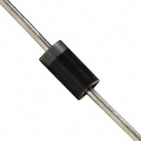
DO-41
0.107(2.7) 0.080(2.0) DIA.
1.0(25.4) MIN.
0.205(5.2) 0.166(4.2)
Mechanical Data
· Case : JEDEC DO-41 molded plastic body · Terminals : Plated axial lead solderable per MIL-STD-750, method 2026 · Polarity : Color band denotes cathode end · Mounting Position : Any · Weight : 0.012 ounce, 0.34 gram
0.034(0.9) 0.028(0.7) DIA. 1.0(25.4) MIN.
Dimensions in inches and (millimeters)
Maximum Ratings And Electrical Characteristics
(Ratings at 25℃ ambient temperature unless otherwise specified, Single phase, half wave 60Hz, resistive or inductive load. For capacitive load, derate by 20%)
Symbols
Maximum recurrent peak reverse voltage Maximum RMS voltage Maximum DC blocking voltage Maximum average forward rectified current 0.375"(9.5mm) lead length TA=75℃ Peak forward surge current 8.3ms single half sine-wave superimposed on rated load (JEDEC method) at TA=75℃ Maximum instantaneous forward voltage at 1.0A Maximum DC reverse current at rated DC blocking voltage Maximum full load reverse current full cycle average. 0.375"(9.5mm) lead length at TL=55℃ Maximum reverse recovery time (Note 1) Typical junction capacitance (Note 2) Operating junction and storage temperature range IR VRRM VRMS VDC I(AV) IFSM VF
1N4933
50 35 50
1N4934
100 70 100
1N4935
200 140 200 1.0 30.0 1.3 5.0
1N4936
400 280 400
1N4937
600 420 600
Units
Volts Volts Volts Amp Amps Volts
μA 100
Trr CJ TJ TSTG
150 15.0 -65 to +150
ns pF ℃
Notes:
(1) Test conditions: IF=1.0A, VR=30V, di/dt=50A/μS, and Irr=10%IRM. (2) Measured at 1MHz and applied reverse voltage of 4.0 Volts.
�RATINGS AND CHARACTERISTIC CURVES 1N4933 THRU 1N4937
FIG.1-TYPICAL FORWARD CURRENT DERATING CURVE
AVERAGE FORWARD CURRENT(A) 1.0 0.8 0.6 0.4 0.2 0 0 25 50 75 100 125 150 175 AMBIENT TEMPERATURE ( ℃)
SINGLE PHASE HALF WAVE 60Hz RESISTIVE OR INDUCTIVE LOAD
FIG.2-MAXIMUM NON-REPETITIVE FORWARD SURGE CURRENT
50
8.3m SINGLE HALF SINE WAVE (JEDEC Method)
PEAK FORWARD SURGE CURRENT(AMPERES)
40 30 20 10 0
1
2
4
6
8 10
20
40
60
100
NUMBER OF CYCLES AT 60Hz
FIG.3-TYPICAL JUNCTION CAPACITANCE
FIG.4-TYPICAL INSTANTANEOUS FORWARD CHARACTERISTICS
60 40 20 10 6 4 2 1 0.1 0.2 0.4 1 2 4 10 20 40 100
TJ=25℃
INSTANTANEOUS FORWARD CURRENT(AMPERES)
200 100 JUNCTION CAPACITANCE(pF)
20 10
3 1
0.3 0.1
TJ=25℃
REVERSE VOLTAGE. (V)
0.03 0.01 0.4 0.6 0.8
Pulse Width=300mS 1% Duty Cycle
1.0
1.2
1.4
1.6
1.8
FIG.5-TEST CIRCUIT DIAGRAM AND REVERSE RECOVERY TIME CHARACTERISTIC
1 8 2
3.8mH/1.4W
INSTANTANEOUS FORWARD VOLTAGE (VOLTS)
R1
115Va 60Hz
10K 2W
3 7
30W 50W NON-INDUCTIVE UNIT UNDER TEST
Trr
Si(t) di/dt=50A/uS
6 5
C.PCLARE HPG 1002
4
1.0Adc FROM CONSTANT VOLTAGE SUPPLY RIPPLE=3mVrms MAX
IFM 1.0
30Vdc CONSTANT VOLTAGE SUPPLY
1APM SLO.BLO FUSE C1 1.OmF 300V
R2 1W 10W NON-INDUCTIVE C1
0
MINIMIZE ALL LEAD LENGTHS A. TEKTRONIX 545A.K PLUG IN PRE AMP P6000 PROBE OR EQUIVALENT R1-ADJUSTED FOR 1.4W BETWEEN POINT 2 OF RELAY AND RECTIFIER INDUCTIVE=3.8uH +10℃ R2-TEN-1W 10W% CARBON CORE IN PARALLEL TA=25 FOR RECTIFIER -0
Zout 11/2W MAX DC TO 2kHz
IRM (REC)
SET TIME BASE FOR 50/100 ns/cm
�
很抱歉,暂时无法提供与“1N4936”相匹配的价格&库存,您可以联系我们找货
免费人工找货