DS1486/DS1486P
RAMified Watchdog Timekeepers
www.maxim-ic.com
ORDERING INFORMATION
FEATURES
§
§
§
§
§
§
§
§
128 kbytes of User NV RAM
Integrated NV SRAM, Real-Time Clock,
Crystal, Power-Fail Control Circuit and
Lithium Energy Source
Totally Nonvolatile with Over 10 years of
Operation in the Absence of Power
Watchdog Timer Restarts an Out-of-Control
Processor
Alarm Function Schedules Real-Time-Related
Activities such as System Wakeup
Programmable Interrupts and Square-Wave
Output
All Registers are Individually Addressable
Through the Address and Data Bus
Interrupt Signals Active in Power-Down
Mode
TEMP
RANGE
0°C to
+70°C
0°C to
+70°C
0°C to
+70°C
0°C to
+70°C
0°C to
+70°C
0°C to
+70°C
PART
DS1486-120
DS1486-120+
DS1486P-120
DS1486P-120+
DS9034PCX
DS9034PCX+
PINPACKAGE
TOP
MARK**
32 EDIP (0.740”)
DS1486-120
32 EDIP (0.740”)
DS1486-120
34 PowerCap®*
34 PowerCap*
DS1486P120
DS1486P120
PowerCap
DS9034PC
PowerCap
DS9034PC
*DS9034PCX PowerCap required (must be ordered separately).
**A ‘+’ indicates lead-free. The top mark will include a ‘+’ symbol
on lead-free devices.
PowerCap is a registered trademark of Dallas Semiconductor.
PIN CONFIGURATIONS
TOP VIEW
1
2
3 DS1486
4
5
6
7
8
9
10
11
12
32
31
30
29
28
27
26
25
24
23
22
21
VCC
A15
DQ0
13
20
DQ6
DQ1
DQ2
14
19
DQ5
15
18
DQ4
GND
16
17
DQ3
INTB (INTB)
A16
A14
A12
A7
A6
A5
A4
A3
A2
A1
A0
INTA/SQW
WE
A13
A8
A9
A11
OE
A10
CE
DQ7
INTB (INTB)
A15
A16
PFO
VCC
WE
OE
CE
DQ7
DQ6
DQ5
DQ4
DQ3
DQ2
DQ1
DQ0
GND
1
2
3
4
5
6
7
8
9
10
11
12
13
14
15
16
17
DS1486P
X1
GND VBAT
X2
34
33
32
31
30
29
28
27
26
25
24
23
22
21
20
19
18
INTA
SQW
A14
A13
A12
A11
A10
A9
A8
A7
A6
A5
A4
A3
A2
A1
A0
34-Pin PowerCap Module Board
(Uses DS9034PCX PowerCap)
128k x 8
32-Pin Encapsulated Package
(32 PIN 740)
1 of 14
REV: 012505
�DS1486/DS1486P
PIN DESCRIPTION
PDIP
PIN
PowerCap
NAME
FUNCTION
1
1
INTB (INTB)
2
3
4
5
6
7
8
9
10
11
12
23
25
26
27
28
31
13
14
15
17
18
19
20
21
3
32
30
25
24
23
22
21
20
19
18
28
29
27
26
31
2
16
15
14
13
12
11
10
9
A16
A14
A12
A7
A6
A5
A4
A3
A2
A1
A0
A10
A11
A9
A8
A13
A15
DQ0
DQ1
DQ2
DQ3
DQ4
DQ5
DQ6
DQ7
16
17
GND
22
8
CE
Active-Low Chip Enable
24
7
OE
Active-Low Output Enable
29
6
WE
30
—
INTA/SQW
32
5
VCC
—
4
PFO
—
33
SQW
—
34
INTA
Active-Low Write Enable
Active-Low, Interrupt A, Open-Drain Output and Square-Wave
Output, Shared. Note: Both functions must not be enabled at the same
time, or a conflict could occur.
Power-Supply Input
Active-Low Power-Fail Output, Open Drain. Requires a pullup
resistor for proper operation.
Square-Wave Output
Active-Low Interrupt A, Output, Open Drain. Requires a pullup
resistor for proper operation.
—
X1, X2, VBAT
Active-Low Interrupt B, Output, Push-Pull
Address Input
Data Input/Output
Ground
Crystal Connections and Battery Connection
2 of 14
�DS1486/DS1486P
DESCRIPTION
The DS1486 is a nonvolatile static RAM with a full-function real-time clock (RTC), alarm, watchdog
timer, and interval timer, which are all accessible in a byte-wide format. The DS1486 contains a lithium
energy source and a quartz crystal, which eliminate the need for any external circuitry. Data contained
within 128K by 8-bit memory and the timekeeping registers can be read or written in the same manner as
byte-wide static RAM. The timekeeping registers are located in the first 14 bytes of memory space. Data
is maintained in the RAMified timekeeper by intelligent control circuitry, which detects the status of VCC
and write-protects memory when VCC is out of tolerance. The lithium energy source can maintain data and
real time for over 10 years in the absence of VCC. Timekeeper information includes hundredths of
seconds, seconds, minutes, hours, day, date, month, and year. The date at the end of the month is
automatically adjusted for months with fewer than 31 days, including correction for leap year. The
RAMified timekeeper operates in either 24-hour or 12-hour format with an AM/PM indicator. The
watchdog timer provides alarm interrupts and interval timing between 0.01 seconds and 99.99 seconds.
The real time alarm provides for preset times of up to one week. Interrupts for both watchdog and RTC
will operate when the system is powered down. Either can provide system “wake-up” signals.
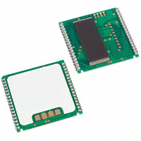
PACKAGES
The DS1486 is available in two packages: a 32-pin DIP module and 34-pin PowerCap module. The 32pin DIP-style module integrates the crystal, lithium energy source, and silicon all in one package. The 32pin PowerCap Module Board is designed with contacts for connection to a separate PowerCap
(DS90934PCX) that contains the crystal and battery. The design allows the PowerCap to be mounted on
top of the DS1486P after the completion of the surface mount process. Mounting the PowerCap after the
surface mount process prevents damage to the crystal and battery due to high temperatures required for
solder reflow. The PowerCap is keyed to prevent reverse insertion. The PowerCap Module Board and
PowerCap are ordered separately and shipped in separate containers. The part number for the PowerCap
is DS9034PCX.
Table 1. Truth Table
VCC
5V ±10%
VBAT
很抱歉,暂时无法提供与“DS1486P-120”相匹配的价格&库存,您可以联系我们找货
免费人工找货