DS1810
5V EconoReset with Push-Pull Output
www.maxim-ic.com
FEATURES
§
§
§
§
§
§
§
PIN ASSIGNMENT
Automatically restarts a microprocessor after
power failure
Maintains reset for 150 ms after VCC returns
to an in-tolerance condition
Reduces need for discrete components
Precision temperature-compensated voltage
reference and voltage sensor
Low-cost TO-92 or space saving surface
mount SOT-23 packages available
Push-Pull output for low current operation
Operating temperature -40°C to +85°C
3
DALLAS
DS1810
Econo
Reset
1 2 3
1
2
TOP VIEW
SOT-23 PACKAGE
See Mech.
Drawings Section
On Website
1 2 3
BOTTOM VIEW
TO-92 PACKAGE
See Mech.
Drawings Section
On Website
PIN DESCRIPTION
TO-92
1
2
3
RST
VCC
GND
Active Low Reset Output
Power Supply
Ground
SOT-23
1
2
3
RST
VCC
GND
Active Low Reset Output
Power Supply
Ground
DESCRIPTION
The DS1810 EconoReset uses a precision temperature reference and comparator circuit to monitor the
status of the power supply (VCC). When an out-of-tolerance condition is detected, an internal power-fail
signal is generated which forces reset to the active state. When VCC returns to an in-tolerance condition,
the reset signal is kept in the active state for approximately 150 ms to allow the power supply and
processor to stabilize.
1 of 5
041002
�DS1810
OPERATION - POWER MONITOR
The DS1810 provides the function of detecting out-of-tolerance power supply conditions and warning a
processor-based system of impending power failure. When VCC is detected as out-of-tolerance, the RST
signal is asserted. On power-up, RST is kept active for approximately 150 ms after the power supply has
reached the selected tolerance. This allows the power supply and microprocessor to stabilize before RST
is released.
BLOCK DIAGRAM (PUSH-PULL OUTPUT) Figure 1
APPLICATION EXAMPLE Figure 2
OUTPUT VALID CONDITIONS
All versions of the DS1810 can maintain a valid output as long as VCC remains above 1.2 volt. However,
the RST outputs on the DS1810 use a push-pull structure which can maintain a valid output below 1.2
volts on an input. To sink current below 1.2 volts, a resistor can be connected from RST to Ground (see
Figure 3). This arrangement will maintain a valid value on the RST outputs even it VCC approaches 0
volts. During both power-up and -down this arrangement will draw current when RST is in the high state.
A value of about 100 kV should be adequate to maintain a valid condition.
2 of 5
�DS1810
APPLICATION DIAGRAM:
RST VALID TO 0 VOLTS VCC ON THE DS1810 Figure 3
TIMING DIAGRAM: POWER-UP Figure 4
TIMING DIAGRAM: POWER-DOWN Figure 5
3 of 5
�DS1810
ABSOLUTE MAXIMUM RATINGS*
Voltage on VCC Pin Relative to Ground
Voltage on RST Relative to Ground
Operating Temperature
Storage Temperature
Soldering Temperature
*
-0.5V to +7.0V
-0.5V to VCC +0.5V
-40°C to +85°C
-55°C to +125°C
260°C for 10 seconds
This is a stress rating only and functional operation of the device at these or any other conditions
above those indicated in the operation sections of this specification is not implied. Exposure to
absolute maximum rating conditions for extended periods of time may affect reliability.
RECOMMENDED DC OPERATING CONDITIONS
PARAMETER
Supply Voltage
SYMBOL
VCC
MIN
1.2
DC ELECTRICAL CHARACTERISTICS
PARAMETER
SYMBOL
Output Voltage @ 0-500 mA
VOH
Output Current @ 2.4V
IOH
Output Current @ 0.4V
IOL
Operating Current VCC < 5.5
ICC
VCC Trip Point (DS1810-5)
VCCTP
VCC Trip Point (DS1810-10)
(-40°C to +85°C)
TYP
MAX
5.5
UNITS
V
NOTES
1
(-40°C to +85°C; VCC=1.2V to 5.5V)
MIN
TYP
MAX
VCC-0.5V VCC-0.1V
350
+10
UNITS
NOTES
V
1
mA
2
mA
2
30
40
mA
3
4.50
4.62
4.75
V
1
VCCTP
4.25
4.37
4.49
V
1
VCC Trip Point (DS1810-15)
VCCTP
4.00
4.12
4.24
V
1
Output Capacitance
COUT
10
pF
AC ELECTRICAL CHARACTERISTICS
PARAMETER
(-40°C to +85°C; VCC=1.2V to 5.5V)
SYMBOL
MIN
TYP
MAX
UNITS
RESET Active Time
tRST
100
150
300
ms
VCC Detect to RST
tRPD
2
5
ms
VCC Slew Rate
(VCCTP (MAX) to VCCTP (MIN))
tF
300
ms
VCC Slew Rate
(VCCTP (MIN) to VCCTP (MAX))
tR
0
ns
tRPU
100
VCC Detect to RST
4 of 5
150
300
ms
NOTES
4
�DS1810
NOTES:
1. All voltages are referenced to ground.
2. Measured with VCC ³ 2.7 volts.
3. Measured with RST output open.
4. tR = 5 ms.
PART MARKING CODES
SOT-23 PACKAGE
“A”, “B”, &“C” represent the device type.
810
DS1810
811
DS1811
812
DS1812
813
DS1813
815
DS1815
816
DS1816
817
DS1817
818
DS1818
“D” represents the device tolerance.
A
5%
B
10%
C
15%
D
20%
5 of 5
�ENGLISH • ???? • ??? • ???
WHAT'S NEW PRODUCTS SOLUTIONS
DESIGN
APPNOTES
SUPPORT
BUY
COMPANY
MEMBERS
DS1810
Part Number Table
Notes:
1. See the DS1810 QuickView Data Sheet for further information on this product family or download the DS1810 full data sheet
(PDF, 128kB).
2. Other options and links for purchasing parts are listed at: http://www.maxim-ic.com/sales.
3. Didn't Find What You Need? Ask our applications engineers. Expert assistance in finding parts, usually within one business day.
4. Part number suffixes: T or T&R = tape and reel; + = RoHS/lead-free; # = RoHS/lead-exempt. More: See full data sheet or Part
Naming Conventions.
5. * Some packages have variations, listed on the drawing. "PkgCode/Variation" tells which variation the product uses.
Part Number
Notes
DS1810R-10+T&R-W
Free
Sample
Buy
Temp
Package: TYPE PINS SIZE
Direct
DRAWING CODE/VAR *
RoHS/Lead-Free?
Materials Analysis
SOT23;3 pin;50
Dwg: 21-0051G (PDF)
Use pkgcode/variation: U3+4*
-40C to +85C RoHS/Lead-Free: Yes
Materials Analysis
DS1810R-15+T&R
5V15%
SOT23;3 pin;50
Dwg: 21-0051G (PDF)
Use pkgcode/variation: U3+4*
-40C to +85C RoHS/Lead-Free: Yes
Materials Analysis
DS1810R-5+T&R
5V-5%
SOT23;3 pin;50
Dwg: 21-0051G (PDF)
Use pkgcode/variation: U3+4*
-40C to +85C RoHS/Lead-Free: Yes
Materials Analysis
DS1810R-15-U
5V15%
SOT23;3 pin;50
Dwg: 21-0051G (PDF)
Use pkgcode/variation: U3-4*
-40C to +85C RoHS/Lead-Free: No
Materials Analysis
�DS1810R-10-U
5V10%
SOT23;3 pin;50
Dwg: 21-0051G (PDF)
Use pkgcode/variation: U3-4*
-40C to +85C RoHS/Lead-Free: No
Materials Analysis
DS1810R-5-U
5V-5%
SOT23;3 pin;50
Dwg: 21-0051G (PDF)
Use pkgcode/variation: U3-4*
-40C to +85C RoHS/Lead-Free: No
Materials Analysis
DS1810R-15/T&R
5V15%
SOT23;3 pin;50
Dwg: 21-0051G (PDF)
Use pkgcode/variation: U3-4*
-40C to +85C RoHS/Lead-Free: No
Materials Analysis
DS1810R-10/T&R
5V10%
SOT23;3 pin;50
Dwg: 21-0051G (PDF)
Use pkgcode/variation: U3-4*
-40C to +85C RoHS/Lead-Free: No
Materials Analysis
DS1810R-5/T&R
5V-5%
SOT23;3 pin;50
Dwg: 21-0051G (PDF)
Use pkgcode/variation: U3-4*
-40C to +85C RoHS/Lead-Free: No
Materials Analysis
DS1810R-10-U+
SOT23;3 pin;50
Dwg: 21-0051G (PDF)
Use pkgcode/variation: U3+4*
-40C to +85C RoHS/Lead-Free: Yes
Materials Analysis
DS1810R-15-U+
SOT23;3 pin;50
Dwg: 21-0051G (PDF)
Use pkgcode/variation: U3+4*
-40C to +85C RoHS/Lead-Free: Yes
Materials Analysis
DS1810R-5-U+
SOT23;3 pin;50
Dwg: 21-0051G (PDF)
Use pkgcode/variation: U3+4*
-40C to +85C RoHS/Lead-Free: Yes
Materials Analysis
DS1810R-10+T&R
5V10%
SOT23;3 pin;50
Dwg: 21-0051G (PDF)
Use pkgcode/variation: U3+4*
-40C to +85C RoHS/Lead-Free: Yes
Materials Analysis
DS1810-15+T&R
5V15%
TO92;3 pin;185
Dwg: 56-G0006-003A (PDF)
Use pkgcode/variation: Q3+4*
-40C to +85C RoHS/Lead-Free: Yes
Materials Analysis
DS1810-5+T&R
5V-5%
TO92;3 pin;185
Dwg: 56-G0006-003A (PDF)
Use pkgcode/variation: Q3+4*
-40C to +85C RoHS/Lead-Free: Yes
Materials Analysis
�DS1810-10+T&R
5V10%
TO92;3 pin;185
Dwg: 56-G0006-003A (PDF)
Use pkgcode/variation: Q3+4*
-40C to +85C RoHS/Lead-Free: Yes
Materials Analysis
DS1810-15/T&R
5V15%
TO92;3 pin;185
Dwg: 56-G0006-003A (PDF)
Use pkgcode/variation: Q3-4*
-40C to +85C RoHS/Lead-Free: No
Materials Analysis
DS1810-10/T&R
5V10%
TO92;3 pin;185
Dwg: 56-G0006-003A (PDF)
Use pkgcode/variation: Q3-4*
-40C to +85C RoHS/Lead-Free: No
Materials Analysis
DS1810-5/T&R
5V-5%
TO92;3 pin;185
Dwg: 56-G0006-003A (PDF)
Use pkgcode/variation: Q3-4*
-40C to +85C RoHS/Lead-Free: No
Materials Analysis
DS1810-15
5V10%
Monitor
TO92;3 pin;185
Dwg: 56-G0006-001A (PDF)
Use pkgcode/variation: Q3-1*
-40C to +85C RoHS/Lead-Free: No
Materials Analysis
DS1810-10
5V15%
Monitor
TO92;3 pin;185
Dwg: 56-G0006-001A (PDF)
Use pkgcode/variation: Q3-1*
-40C to +85C RoHS/Lead-Free: No
Materials Analysis
DS1810-5
5V-5%
Monitor
TO92;3 pin;185
Dwg: 56-G0006-001A (PDF)
Use pkgcode/variation: Q3-1*
-40C to +85C RoHS/Lead-Free: No
Materials Analysis
DS1810-15+
TO92;3 pin;185
Dwg: 56-G0006-001A (PDF)
Use pkgcode/variation: Q3+1*
-40C to +85C RoHS/Lead-Free: Yes
Materials Analysis
DS1810-5+
TO92;3 pin;185
Dwg: 56-G0006-001A (PDF)
Use pkgcode/variation: Q3+1*
-40C to +85C RoHS/Lead-Free: Yes
Materials Analysis
DS1810-10+
TO92;3 pin;185
Dwg: 56-G0006-001A (PDF)
Use pkgcode/variation: Q3+1*
-40C to +85C RoHS/Lead-Free: Yes
Materials Analysis
Didn't Find What You Need?
�CONTACT US: SEND US AN EMAIL
Copyright 2007 by Maxim Integrated Products, Dallas Semiconductor • Legal Notices • Privacy Policy
�
很抱歉,暂时无法提供与“DS1810-5+TR”相匹配的价格&库存,您可以联系我们找货
免费人工找货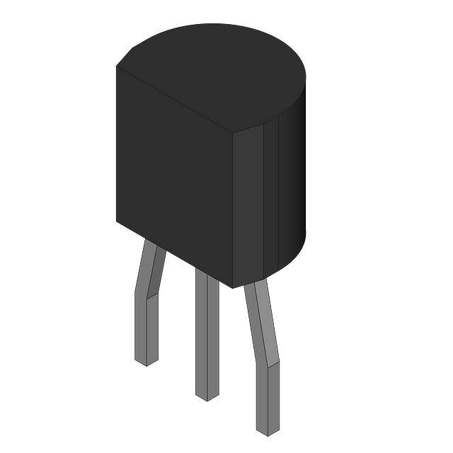


 工商网监
湘ICP备2023018690号
工商网监
湘ICP备2023018690号
