19-4318; Rev 0; 11/08
MAX14502 Evaluation Kit
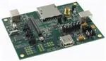
The MAX14502 evaluation kit (EV kit) provides a proven
design to evaluate the MAX14502 Hi-Speed USB-to-SD
card reader. The EV kit includes Windows® 2000/XPand Windows Vista®-compatible software that provides
a simple graphical user interface (GUI) for exercising
the features of the MAX14502.
The MAX14502 EV kit has a built-in USB-to-I2C bridge,
allowing a PC to access the internal I2C registers of the
MAX14502, as well as providing the power for the EV kit.
The MAX14502 EV kit PCB comes with a
MAX14502AETL+ installed. The EV kit can also be used
to evaluate the MAX14500AETL+, MAX14501AETL+, and
MAX14503AETL+ by replacing the MAX14502AETL+,
and changing the crystal oscillator frequency according
to the device used or by applying an appropriate external
clock on the SMA connector. Contact the factory for free
samples of the MAX14500AETL+, MAX14501AETL+, and
MAX14503AETL+.
Windows and Windows Vista are registered trademarks of
Microsoft Corp.
Features
♦ Simple and I2C Control Modes
♦ On-Board SD Card Socket, USB Type-A, and USB
Type-B Connectors
♦ Default 19.2MHz Input Clock, Alternative Input
Clock Connector Provided
♦ External Microprocessor Connections Provided
♦ Windows 2000/XP- and Windows Vista
(32-Bit)-Compatible Software
♦ On-Board USB-to-I2C Bridge
♦ USB Powered (Cable Included)
♦ Lead(Pb)-Free and RoHS Compliant
♦ Proven PCB Layout
♦ Fully Assembled and Tested
Ordering Information
PART
TYPE
MAX14502EVKIT+
EV Kit
+Denotes lead(Pb)-free and RoHS compliant.
Component List
DESIGNATION
QTY
C1–C9, C13,
C14, C16–C19,
C22, C23, C30
18
1μF ±10%, 10V X5R ceramic
capacitors (0603)
Murata GRM188R61A105K
C10, C11, C15
3
47μF ±10%, 10V tantalum
capacitors (Size D)
KEMET B45197A2476K409
5
4.7μF ±10%, 10V X5R ceramic
capacitors (0805)
Murata GRM219R61A475K
C12, C26–C29
DESCRIPTION
C20, C21, C24,
C25
4
18pF ±5%, 50V C0G ceramic
capacitors (0603)
Murata GRM1885C1H180J
C31
1
0.01μF ±10%, 16V X7R ceramic
capacitor (0603)
Murata GRM188R71C103K
1
0.1μF ±10%, 16V X7R ceramic
capacitor (0603)
Murata GRM188R71C104K
C32
D1, D2
2
Green LEDs (0603)
D3
1
Red LED (0603)
D4
1
Yellow LED (0603)
DESIGNATION
QTY
FB1–FB8
8
120 at 100MHz, 200mA ferrite
beads (0603)
Murata BLM18RK121SN1
J1
1
SD memory card standard
connector
J2, J6
2
USB type-B right-angle receptacles
J3
1
USB type-A right-angle receptacle
J4
1
Dual-row (2 x 15) 30-pin header
J5
1
SMA PC-mount connector
J7
0
Not installed, dual-row (2 x 5)
10-pin header
JU1, JU5, JU6,
JU9–JU16
11
2-pin headers
JU2, JU17,
JU18
3
3-pin headers
JU3, JU4, JU7,
JU8
4
4-pin headers
JU19–JU24
0
Not installed, 3-pin headers
2
n-channel low-threshold-voltage
FETs (3 SOT23)
Q1, Q2
DESCRIPTION
________________________________________________________________ Maxim Integrated Products
For information on other Maxim products, visit Maxim’s website at www.maxim-ic.com.
1
Evaluates: MAX14502
General Description
�Evaluates: MAX14502
MAX14502 Evaluation Kit
Component List (continued)
DESIGNATION
QTY
DESIGNATION
DESCRIPTION
R1, R5, R6, R7,
R13, R18, R19,
R22
8
10k� ±5% resistors (0603)
R2
1
68.1k� ±1% resistor (0603)
R3
1
27.4k� ±1% resistor (0603)
R4
1
6.19k� ±1% resistor (0603)
R8, R14–R17
5
300� ±5% resistors (0603)
R9, R25
2
10.5k� ±1% resistors (0603)
R10, R26
2
6.49k� ±1% resistors (0603)
R11, R12, R27,
R28
4
100k� ±5% resistors (0603)
R20, R21
2
3.9k� ±5% resistors (0603)
R23, R24
2
33.2� ±1% resistors (0603)
QTY
DESCRIPTION
U3
1
Single CMOS switch debouncer
(4 SOT143)
Maxim MAX6816EUS+
U4
1
USB peripheral controller
(24 TQFN-EP*)
Maxim MAX3420EETG+
U5
1
Microcontroller (68 QFN-EP*)
Maxim MAXQ2000-RAX+
U6
1
2.5V LDO regulator (5 SC70)
Maxim MAX8511EXK25+
U8
1
3.0V LDO regulator (5 SC70)
Maxim MAX8510EXK30+
U9
1
Dual buffer with Schmitt trigger
inputs (6 SC70)
VCC, VIO,
VIO_U1, VOSC,
VSD, VSD_C,
VTM
7
Test points, white
R29
0
Not installed, resistor (0603)
R30–R41
12
0� ±5% resistors (0603)
R42, R43
0
Not installed, resistors (0402)
SW1
1
SPDT slide switch
SW2
1
Momentary pushbutton switch
Y1
1
19.2MHz crystal oscillator
1
12MHz crystal
TP1
1
Test point, red
Y2
TP2
1
Test point, black
Y3
1
20MHz crystal
—
18
Shunts
1
Hi-Speed USB-to-SD card reader
(40 TQFN-EP*)
Maxim MAX14502AETL+
—
1
PCB: MAX14502 Evaluation Kit+
2
200mA adjustable output LDO
regulators
(6 SOT23)
Maxim MAX8880EUT+
U1
U2, U7
*EP = Exposed pad.
Component Suppliers
SUPPLIER
PHONE
WEBSITE
KEMET Corp.
864-963-6300
www.kemet.com
Murata Electronics North America, Inc.
770-436-1300
www.murata-northamerica.com
Note: Indicate that you are using the MAX14502 when contacting these component suppliers.
MAX14502 EV Kit Files
FILE
INSTALL.EXE
MAX14502.EXE
UNINST.INI
2
DESCRIPTION
Installs the EV kit files on your computer
Application program
Uninstalls the EV kit software
_______________________________________________________________________________________
�MAX14502 Evaluation Kit
5)
Insert the SD card into the SD card socket (J1).
6)
Before beginning, the following equipment is needed:
•
MAX14502 EV kit (USB cables included)
Connect the USB type-B connector (J6) to one of
the PC USB ports.
7)
Verify that the D2 green LED and the D4 yellow
LED on the EV kit board are lit.
•
A user-supplied Windows 2000-/XP-/Vista-compatible PC with two spare USB ports
8)
Connect the USB mouse to the type-A USB connector (J3).
•
A user-supplied SD card
9)
•
A user-supplied USB mouse (or other low-/fullspeed USB device)
Connect the USB type-B connector (J2) to another
PC USB port.
10) Verify that the PC recognizes the USB mouse.
Required Equipment
Note: In the following sections, software-related items
are identified by bolding. Text in bold refers to items
directly from the EV kit software. Text in bold and
underlined refers to items from the Windows operating
system.
Procedure
The MAX14502 EV kit is fully assembled and tested.
Follow the steps below to verify board operation:
1) Visit www.maxim-ic.com/evkitsoftware to download the latest version of the EV kit software,
14502Rxx.ZIP. Save the EV kit software to a temporary folder and uncompress the ZIP file.
2)
Install the EV kit software on your computer by running the INSTALL.EXE program inside the temporary folder. The program files are copied and icons
are created in the Windows Start | Programs
menu.
3)
Verify that all jumpers are in their default positions,
as shown in Table 1.
4)
Move slider switch SW1 to the on position.
11) Start the MAX14502 EV kit software by opening its
icon in the Start | Programs menu.
12) The EV kit software main window appears, as shown
in Figure 1. Verify that Hardware: Connected is displayed on the status bar at the bottom of the software main window.
13) In the Bridge Mode group box, select the Pass
Thru radio button to set the MAX14502 in pass thru
mode. Verify that MAX14502: Simple Control/Pass
Thru Mode is displayed on the status bar.
14) In the Bridge Mode group box, select the Card
Reader radio button to set the MAX14502 in card
reader mode. Verify that MAX14502: Simple
Control/Card Reader Mode is displayed on the
status bar.
15) Verify that the PC recognizes the SD card.
16) On the EV kit board, verify that the D1 green LED
is lit, indicating that the internal microcontroller in
the MAX14502 is activated in card reader mode.
Figure 1. MAX14502 Software Main Window (Simple Control Mode)
_______________________________________________________________________________________
3
Evaluates: MAX14502
Quick Start
�Evaluates: MAX14502
MAX14502 Evaluation Kit
Figure 2. MAX14502 Software Main Window (Graphical View Tab)
17) Press the Change To I2C Control button to set the
MAX14502 in I 2 C control mode. Verify that
MAX14502 Connected on Address: 0xE0 is displayed on the status bar. All the I2C register controls are available on the GUI, as shown in Figure 2.
18) Verify that the PC recognizes the USB mouse.
4
Detailed Description of Software
The software sets the MAX14502 in either simple or I2C
control mode.
In simple control mode, the user can set the device in
either pass thru or card reader mode. When the EV kit
is connected correctly, the software automatically monitors the status of the BERR pin.
There are two tabs when the software works in I2C control mode.
_______________________________________________________________________________________
�MAX14502 Evaluation Kit
Software Menu Bar
Select File | Exit to exit the application.
The Help menu item gives information about this EV kit
software.
The embedded picture shows the current mode of the
device. A command log window displays the read and
write operations on the MAX14502.
The status register (0x12) bit values are displayed in
the Status group box. When the solid circle is green, it
indicates a value of 1. When the solid circle is gray, it
indicates a value of 0.
When the INT pin is asserted, the solid circle beside the
INT Pin label turns red. Otherwise, it is gray.
When the on-board USB-to-I2C bridge detects the presence of the MAX14502, the solid circle beside the
Ready label turns green. If the EV kit is not connected
correctly, the circle is gray.
Detailed Description of Hardware
The MAX14502 operates in pass thru and card reader
mode. The device can be controlled in two ways: simple control method and I2C control method.
The MAX14502 EV kit board provides a proven layout
for evaluating the device. The EV kit comes with one
MAX14502AETL+ installed.
Power Supplies
By default, the EV kit is powered by USB (J6). The different power supplies for the MAX14502 can be
applied according to user requirements. See Table 1
for possible power-supply configurations.
Press the Query button to read all the register values.
Press the Load… button to load the register settings
from a text file.
Press the Save… button to save the current register
settings to a text file.
By default, the MAX14502 uses the on-board 19.2MHz
crystal oscillator output as the input clock. The user can
apply alternative clocks on the SMA connector (J5) and
set the shunt of jumper JU2 in the 2-3 position.
Press the Reset EVKIT button to reset the EV kit,
including the USB re-enumeration on J6. The
MAX14502 is reset to its power-on-reset (POR) state.
The MAX14502 is reset by pressing and releasing
switch SW2.
Alternative Input Clock
Reset MAX14502
Register View Tab
On the Register View tab (Figure 3), detailed names
and values of the registers are displayed.
Refer to the MAX14500–MAX14503 IC data sheet for
the detailed descriptions of all the registers available in
I2C control mode.
_______________________________________________________________________________________
5
Evaluates: MAX14502
Graphical View Tab
When the Graphical View tab (Figure 2) is selected, a
user has access to all of the I2C registers through the
on-board USB-to-I2C bridge.
�Evaluates: MAX14502
MAX14502 Evaluation Kit
Figure 3. MAX14502 Software Main Window (Register View Tab)
6
_______________________________________________________________________________________
�MAX14502 Evaluation Kit
Evaluates: MAX14502
Table 1. MAX14502 EV Kit Jumper Descriptions (JU1–JU18)
JUMPER
JU1
JU2
JU3
JU4
JU5
JU6
JU7
JU8
JU9
JU10
JU11
JU12
JU13
JU14
JU15
JU16
JU17
SHUNT
1-2*
Open
CCRD_PRST pin pulled up to VSD by R1
CCRD_PRST pin has no pullup resistor
1-2*
Input clock is on-board 19.2MHz crystal oscillator output
2-3
1-2
Input clock is applied on SMA connector
EV kit powered by EXT_5V power supply
1-3*
EV kit powered by USB power supply on J6
1-4
EV kit powered by USB power supply on J2
1-2
1-3
I2C_SEL pin connected to GND
I2C_SEL pin connected to VIO
1-4*
I2C_SEL pin controlled by MAXQ2000 GPO pin
1-2*
SCL pin connected to the on-board USB-to-I2C bridge
Open
1-2*
SCL pin disconnected from the on-board USB-to-I2C bridge
SDA pin connected to the on-board USB-to-I2C bridge
Open
SDA pin disconnected from the on-board USB-to-I2C bridge
1-2
ADD pin connected to GND
1-3
1-4*
ADD pin connected to VIO
ADD pin controlled by MAXQ2000 GPO pin
1-2
MODE pin connected to GND
1-3
MODE pin connected to VIO
1-4*
1-2*
MODE pin controlled by MAXQ2000 GPO pin
BERR/INT pin connected to MAXQ2000 GPI pin
Open
1-2*
BERR/INT pin disconnected from MAXQ2000 GPI pin
BUSY pin connected to MAXQ2000 GPI pin
Open
1-2*
BUSY pin disconnected from MAXQ2000 GPI pin
RST pin controlled by MAXQ2000 GPO pin
Open
RST pin disconnected from MAXQ2000 GPO pin
1-2*
VCC connected to on-board +3.3V power supply
Open
1-2*
VCC applied externally on the VCC test point
VTM connected to on-board +3.3V power supply
Open
1-2*
Open
1-2*
Open
VTM applied externally on the VTM test point
On-board crystal oscillator powered by on-board +3V power supply
On-board crystal oscillator powered externally on the VOSC test point
VSD connected to on-board +3.3V power supply
VSD applied externally on the VSD test point
1-2*
SD card powered by on-board +3.3V power supply
Open
1-2*
SD card powered externally on the VSD_C test point
VIO connected to on-board +3.3V power supply
2-3
Open
JU18
DESCRIPTION
VIO connected to MAXQ2000 VDDIO
VIO applied externally on the VIO test point
1-2*
2-3
VIO_U1 connected to on-board +3.3V power supply
VIO_U1 connected to MAXQ2000 VDDIO
Open
VIO_U1 applied externally on the VIO_U1 test point
*Default position.
_______________________________________________________________________________________
7
�Evaluates: MAX14502
MAX14502 Evaluation Kit
Figure 4a. MAX14502 EV Kit Schematic (Sheet 1 of 3)
8
_______________________________________________________________________________________
�MAX14502 Evaluation Kit
Evaluates: MAX14502
Figure 4b. MAX14502 EV Kit Schematic (Sheet 2 of 3)
_______________________________________________________________________________________
9
�Evaluates: MAX14502
MAX14502 Evaluation Kit
Figure 4c. MAX14502 EV Kit Schematic (Sheet 3 of 3)
10
______________________________________________________________________________________
�MAX14502 Evaluation Kit
Evaluates: MAX14502
Figure 5. MAX14502 EV Kit Component Placement Guide—Component Side
______________________________________________________________________________________
11
�Evaluates: MAX14502
MAX14502 Evaluation Kit
Figure 6. MAX14502 EV Kit PCB Layout—Component Side
12
______________________________________________________________________________________
�MAX14502 Evaluation Kit
Evaluates: MAX14502
Figure 7. MAX14502 EV Kit PCB Layout—Inner Layer 2
______________________________________________________________________________________
13
�Evaluates: MAX14502
MAX14502 Evaluation Kit
Figure 8. MAX14502 EV Kit PCB Layout—Inner Layer 3
14
______________________________________________________________________________________
�MAX14502 Evaluation Kit
Evaluates: MAX14502
Figure 9. MAX14502 EV Kit PCB Layout—Solder Side
Maxim cannot assume responsibility for use of any circuitry other than circuitry entirely embodied in a Maxim product. No circuit patent licenses are
implied. Maxim reserves the right to change the circuitry and specifications without notice at any time.
Maxim Integrated Products, 120 San Gabriel Drive, Sunnyvale, CA 94086 408-737-7600 ____________________ 15
© 2008 Maxim Integrated Products
is a registered trademark of Maxim Integrated Products, Inc.
�


 工商网监
湘ICP备2023018690号
工商网监
湘ICP备2023018690号
