19-3097; Rev 2; 8/05
KIT
ATION
EVALU
E
L
B
A
AVAIL
White LED 1x/1.5x Charge Pump
for Main and Sub-Displays
The MAX1575 charge pump drives up to four white
LEDs in the main display and up to two white LEDs in
the sub-display with regulated constant current for uniform intensity. By utilizing adaptive 1x/1.5x chargepump modes and very-low-dropout current regulators,
it achieves high efficiency over the full 1-cell lithiumbattery input voltage range. A 1MHz fixed-frequency
switching allows for tiny external components, and the
regulation scheme is optimized to ensure low EMI and
low input ripple.
The MAX1575 uses an external resistor to set the fullscale 100% LED current. Two enable inputs, ENM and
ENS, are used for simple on/off controls for the main and
sub-displays, respectively. By repeatedly pulsing either
enable input, the LEDs can be dimmed in multiple steps
down to 5%. Once the desired brightness is set, the
MAX1575 maintains that brightness setting as long as
the enable input is kept high. If an enable input is kept
low for more than 2ms, the LED current for the respective display is set to zero. If both enable inputs are kept
low for more than 2ms, the MAX1575 enters shutdown.
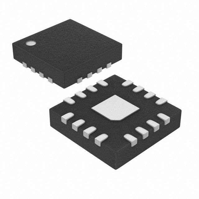
The MAX1575 is available in a 16-pin 4mm x 4mm thin
QFN package (0.8mm max height).
Applications
Cell Phones with Main and Sub-Displays
Features
♦ Powers Main and Sub-Display LEDs
♦ 85% Average Efficiency (PLED / PBATT) Over Li+
Battery Discharge
♦ 2% LED Current Matching
♦ Up to 30mA/LED Drive Capability
♦ Adaptive 1x/1.5x Mode Switchover
♦ Low Input Ripple and EMI
♦ Individual 5% to 100% Dimming Through
Single-Wire Serial Pulse Interface
♦ Low 0.1µA Shutdown Current
♦ 2.7V to 5.5V Supply Voltage Range
♦ Soft-Start Limits Inrush Current
♦ Output-Overvoltage Protection
♦ Thermal-Shutdown Protection
♦ 16-Pin Thin QFN 4mm x 4mm Package
Ordering Information
PART
TEMP RANGE
PIN-PACKAGE
MAX1575ETE
-40°C to +85°C
16 Thin QFN 4mm x 4mm
MAX1575ETE+
-40°C to +85°C
16 Thin QFN 4mm x 4mm
+ Denotes lead-free package.
Typical Operating Circuit
PDAs/Smart Phones with Up to Six White LEDs
1μF
Pin Configuration
C1P
GND
LED1
LED2
LED3
TOP VIEW
12
11
10
9
2.7V TO 5.5V
LED4
IN 14
7
LED5
6
LED6
5
ENM
1
2
3
4
OUT
SET
ENS
+
C2P
C1P 16
THIN QFN
4mm x 4mm
1μF
MAX1575
8
MAX1575
OUT
IN
1μF
C1N 13
C2N 15
C1N
GND
MAIN
LED1
LED2
ENABLE MAIN
ON/OFF
AND DIMMING
ENM
ENABLE SUB
ON/OFF
AND DIMMING
ENS
LED3
LED4
LED5
SUB
SET
LED6
RSET
C2P
C2N
1μF
________________________________________________________________ Maxim Integrated Products
For pricing, delivery, and ordering information, please contact Maxim/Dallas Direct! at
1-888-629-4642, or visit Maxim’s website at www.maxim-ic.com.
1
MAX1575
General Description
�MAX1575
White LED 1x/1.5x Charge Pump
for Main and Sub-Displays
ABSOLUTE MAXIMUM RATINGS
IN, OUT, ENM, ENS to GND..................................-0.3V to +6.0V
SET, LED_, C1N, C2N to GND.....................-0.3V to (VIN + 0.3V)
C1P, C2P to GND.............................................................-0.3V to
the greater of (VOUT + 1V) or (VIN + 1V)
OUT Short Circuit to GND ..........................................Continuous
Continuous Power Dissipation (TA = +70°C)
16-Pin Thin QFN 4mm x 4mm
(derate 16.9 mW/°C above +70°C) ............................1349mW
Junction Temperature ......................................................+150°C
Storage Temperature Range .............................-65°C to +150°C
Lead Temperature (soldering, 10s) .................................+300°C
Stresses beyond those listed under “Absolute Maximum Ratings” may cause permanent damage to the device. These are stress ratings only, and functional
operation of the device at these or any other conditions beyond those indicated in the operational sections of the specifications is not implied. Exposure to
absolute maximum rating conditions for extended periods may affect device reliability.
ELECTRICAL CHARACTERISTICS
(VIN = 3.6V, VGND = 0V, ENM = ENS = IN, RSET = 6.81kΩ, CIN = C1 = C2 = COUT = 1µF, TA = -40°C to +85°C, unless otherwise
noted. Typical values are at TA = +25°C.) (Note 1)
PARAMETER
CONDITIONS
IN Operating Voltage
Undervoltage-Lockout Threshold
MIN
No-Load Supply Current
Shutdown Supply Current
2.25
SET-to-LED_ Current Ratio (ILED_ / ISET)
LED Current Accuracy
LED-to-LED Current Matching (Note 2)
Maximum LED_ Sink Current
V
5
V
1MHz switching in 1.5x mode
2
No switching in 1x mode,10% setting
0.5
ENM = ENS = OUT = GND
0.1
ENM = ENS = GND
mA
2
ms
0.6
V
0.01
1
10
130
TA = -40°C to +85°C
30
130
100% setting
234
TA = +25°C to +85°C
-8
TA = -40°C to +85°C
-9.5
µA
2
TA = 0°C to +85°C
±2
µA
A/A
+8
+9.5
±1.5
µA
-5
TA = -40°C to +85°C
-6.5
RSET = 4.53kΩ
27.4
30.0
60
100
mV
90
100
110
mV
0.01
1
µA
1
2.5
4.2
10
(Note 3)
VLED falling
LED Leakage in Shutdown
ENM = ENS = GND, VLED_ = 5.5V
Maximum OUT Current
VIN ≥ 3.4V, VOUT = 3.9V, 100% setting
1.5x mode (1.5 x VIN - VOUT) / IOUT
Switching Frequency
ENM = ENS = GND
ENM, ENS High Voltage
VIN = 2.7V to 5.5V
ENM, ENS Low Voltage
VIN = 2.7V to 5.5V
ENM, ENS Input Current
VEN_ = 0V or 5.5V
Shutdown Delay
From falling edge of ENM and ENS
+6.5
mA
Ω
1
MHz
5
kΩ
1.6
1.0
%
mA
120
1x mode (VIN - VOUT) / IOUT
OUT Pulldown Resistance
+5
%
TA = +25°C to +85°C
LED_ 1x-to-1.5x Transition Threshold
2
V
2.60
VOUT rising
LED_ Dropout Voltage
Open-Loop OUT Resistance
5.5
2.45
mV
SET Bias Voltage
SET Current Range
UNITS
35
Soft-Start Time
SET Leakage in Shutdown
MAX
2.7
VIN falling
Undervoltage-Lockout Hysteresis
OUT Overvoltage-Protection Threshold
TYP
V
0.4
V
0.01
1
µA
2
3.3
ms
_______________________________________________________________________________________
�White LED 1x/1.5x Charge Pump
for Main and Sub-Displays
(VIN = 3.6V, VGND = 0V, ENM = ENS = IN, RSET = 6.81kΩ, CIN = C1 = C2 = COUT = 1µF, TA = -40°C to +85°C, unless otherwise
noted. Typical values are at TA = +25°C.) (Note 1)
PARAMETER
CONDITIONS
MIN
TYP
MAX
UNITS
500
µs
tLO (ENM, ENS) (Figure 1)
0.5
tHI (ENM, ENS) (Figure 1)
0.5
µs
50
µs
Initial tHI (ENM, ENS) (Figure 1)
Only required for first EN_ pulse
Thermal-Shutdown Threshold
+160
°C
Thermal-Shutdown Hysteresis
20
°C
Note 1: Specifications to -40°C are guaranteed by design and not production tested.
Note 2: LED current matching is defined as: (ILED - IAVG) / IAVG
Note 3: Dropout voltage is defined as the LED_-to-GND voltage at which current into the LED drops 10% from the LED current at
VLED_ = 0.2V.
Typical Operating Characteristics
(VIN = 3.6V, ENM = ENS = IN, circuit of Figure 2, TA = +25°C, unless otherwise noted.)
INPUT CURRENT vs. SUPPLY VOLTAGE
DRIVING SIX WHITE LEDs
20mA/LED
60
50
2mA/LED
8mA/LED
40
140
120
100
SUPPLY VOLTAGE FALLING
8mA/LED
80
200
180
60
40
30
20
3.0
3.3
3.6
3.9
100
80
60
8mA/LED
2mA/LED
20
0
2.7
4.2
20mA/LED
120
3.0
3.3
3.6
4.2
3.9
2.7
3.0
3.3
3.6
3.9
SUPPLY VOLTAGE (V)
SUPPLY VOLTAGE (V)
SUPPLY VOLTAGE (V)
INPUT CURRENT vs. SUPPLY VOLTAGE
DRIVING TWO WHITE LEDs
INPUT RIPPLE vs. SUPPLY VOLTAGE
DRIVING SIX WHITE LEDs
LED CURRENT MATCHING
vs. SUPPLY VOLTAGE
120
100
8mA/LED
80
2mA/LED
60
50
20mA/LED
40
30
8mA/LED
20
40
0
3.0
3.3
3.6
SUPPLY VOLTAGE (V)
3.9
4.2
MAX1575 toc06
20
19
17
0
2.7
4.2
18
2mA/LED
10
20
21
LED CURRENT (mA)
20mA/LED
140
60
INPUT RIPPLE (mVP-P)
SUPPLY VOLTAGE FALLING
160
22
MAX1575 toc05
180
70
MAX1575 toc04
200
INPUT CURRENT (mA)
2mA/LED
0
2.7
140
40
20
SUPPLY VOLTAGE FALLING
SUPPLY VOLTAGE FALLING
160
INPUT CURRENT (mA)
70
20mA/LED
160
INPUT CURRENT (mA)
80
180
MAX1575 toc02
90
EFFICIENCY (%)
200
MAX1575 toc01
100
INPUT CURRENT vs. SUPPLY VOLTAGE
DRIVING FOUR WHITE LEDs
MAX1575 toc03
EFFICIENCY vs. SUPPLY VOLTAGE
DRIVING SIX WHITE LEDs
2.7
3.1
3.5
3.9
4.3
4.7
SUPPLY VOLTAGE (V)
5.1
5.5
2.7
3.1
3.5
3.9
4.3
4.7
5.1
5.5
SUPPLY VOLTAGE (V)
_______________________________________________________________________________________
3
MAX1575
ELECTRICAL CHARACTERISTICS (continued)
�Typical Operating Characteristics (continued)
(VIN = 3.6V, ENM = ENS = IN, circuit of Figure 2, TA = +25°C, unless otherwise noted.)
OUTPUT CURRENT vs. SUPPLY VOLTAGE
DRIVING SIX LEDs AT 20mA EACH
LED CURRENT (mA)
121
120
119
MAX1575 toc09
MAX1575 toc08
122
OPERATING WAVEFORMS (1x)
LED CURRENT vs. RSET
100
MAX1575 toc07
123
OUTPUT CURRENT (mA)
MAX1575
White LED 1x/1.5x Charge Pump
for Main and Sub-Displays
VOUT
200mV/div
AC-COUPLED
VIN
50mV/div
AC-COUPLED
IIN
50mA/div
10
118
100% BRIGHTNESS SETTING
0mA
1
117
2.7
3.1
3.5
3.9
4.3
4.7
5.1
1
5.5
10
RSET (kΩ)
SUPPLY VOLTAGE (V)
MAX1575 toc12
MAX1575 toc11
MAX1575 toc10
VIN
MAIN STARTUP WITH SUB-DISPLAY ON
STARTUP WAVEFORMS
OPERATING WAVEFORMS (1.5x)
VOUT
400ns/div
100
VENM
200mV/div
AC-COUPLED AND VENS
5V/div
50mV/div
AC-COUPLED
100mA/div
IIN
5V/div
VENM
IIN
100mA/div
0
0
50mA/div
IIN
2V/div
VOUT
VOUT
500mV/div
0
0
1ms/div
1ms/div
400ns/div
DIMMING RESPONSE
LINE TRANSIENT 3.8V TO 3.3V TO 3.8V
MAX1575 toc13
MAX1575 toc14
2V/div
VENM
AND VENS
50mA/div
VIN
1V/div
1V/div
AC-COUPLED
VOUT
IOUT
0
50mA/div
IOUT
2V/div
VOUT
0mA
10ms/div
4
40μs/div
_______________________________________________________________________________________
�White LED 1x/1.5x Charge Pump
for Main and Sub-Displays
PIN
NAME
1
C2P
Transfer-Capacitor 2 Positive Connection. Connect a 1µF ceramic capacitor from C2P to C2N.
2
OUT
Output. Connect a 1µF ceramic capacitor from OUT to GND. Connect OUT to the anodes of all the LEDs.
OUT is internally pulled down with 5kΩ during shutdown.
3
SET
Current-Set Input. Connect a resistor (RSET) from SET to GND to set the maximum LED current. ILED(MAX) =
234 × 0.6V / RSET. SET is internally biased to 0.6V. SET is high impedance during shutdown.
ENS
Enable and Dimming Control for LED5 and LED6 (Sub-Display). The first time ENS goes high (50µs min),
LED5 and LED6 turn on at 100% brightness. Pulsing ENS low dims the LEDs in multiple steps. If ENS is held
low for more than 2ms (typ), LED5 and LED6 turn off. When ENM and ENS are both held low for more than
2ms (typ), the IC goes into shutdown mode. See Figure 1.
5
ENM
Enable and Dimming Control for LED1–LED4 (Main Display). The first time ENM goes high (50µs min),
LED1–LED4 turn on at 100% brightness. Pulsing ENM low dims the LEDs in multiple steps. If ENM is held low for
more than 2ms (typ), LED1–LED4 turn off. When ENM and ENS are both held low for more than 2ms (typ), the IC
goes into shutdown mode. See Figure 1.
6
LED6
7
LED5
8
LED4
9
LED3
10
LED2
11
LED1
12
GND
13
C1N
4
14
IN
15
C2N
16
C1P
—
EP
FUNCTION
Sub-Display LEDs Cathode Connection. Current flowing into LED_ is described in the ENS and SET
descriptions above. The charge pump regulates the lowest-enabled LED_ voltage to 180mV. Connect LED_
to IN if the LED is not populated. LED_ is high impedance during shutdown.
Main-Display LEDs Cathode Connection. Current flowing into LED_ is described in the ENM and SET
descriptions above. The charge pump regulates the lowest-enabled LED_ voltage to 180mV. Connect LED_
to IN if the LED is not populated. LED_ is high impedance during shutdown.
Ground. Connect GND as close as possible to system ground and to the ground of the input bypass
capacitor.
Transfer-Capacitor 1 Negative Connection. Connect a 1µF ceramic capacitor from C1P to C1N.
Supply Voltage Input. Connect a 1µF ceramic capacitor from IN to GND. The input voltage range is 2.7V to
5.5V. IN is high impedance during shutdown.
Transfer-Capacitor 2 Negative Connection. Connect a 1µF ceramic capacitor from C2P to C2N.
Transfer-Capacitor 1 Positive Connection. Connect a 1µF ceramic capacitor from C1P to C1N.
Exposed Paddle. Connect the exposed paddle to GND.
Detailed Description
The MAX1575 charge pump drives up to four white
LEDs in the main display and up to two white LEDs in
the sub-display with regulated constant current for
uniform intensity. By utilizing adaptive 1x/1.5x chargepump modes and very-low-dropout current regulators, it
achieves high efficiency over the 1-cell lithium-battery
input voltage range. 1MHz fixed-frequency switching
allows for tiny external components and low input ripple.
1x to 1.5x Switchover
When VIN is higher than VOUT, the MAX1575 operates in
1x mode and VOUT is pulled up to VIN. The internal current regulators regulate the LED current. As VIN drops,
VLED_ eventually falls below the switchover threshold of
100mV and the MAX1575 starts switching in 1.5x mode.
When the input voltage rises above VOUT by about 50mV,
the MAX1575 switches back to 1x mode.
Soft-Start
The MAX1575 includes soft-start circuitry to limit inrush
current at turn-on. When starting up, the output capacitor
is charged directly from the input with a ramped current
source (with no charge-pump action) until the output voltage approaches the input voltage. Once this occurs, the
charge pump determines if 1x or 1.5x mode is required.
In the case of 1x mode, the soft-start is terminated and
normal operation begins. During the soft-start time, the
output current is set to 5% of the maximum set by RSET.
In the case of 1.5x mode, soft-start operates until the lowest of LED1–LED6 reaches regulation. If an overload condition occurs, soft-start repeats every 2ms. If the output is
shorted to ground (or


 工商网监
湘ICP备2023018690号
工商网监
湘ICP备2023018690号
