EVALUATION KIT AVAILABLE
MAX16909
36V, 220kHz to 1MHz Step-Down Converter
with Low Operating Current
General Description
Features
The MAX16909 is a 3A, current-mode, step-down converter with an integrated high-side switch. The device is
designed to operate with input voltages from 3.5V to 36V
while using only 30FA quiescent current at no load. The
switching frequency is adjustable from 220kHz to 1MHz
by an external resistor and can be synchronized to an
external clock. The output voltage is pin selectable to
be 5V fixed or adjustable from 1V to 10V. The wide input
voltage range along with its ability to operate at high duty
cycle during undervoltage transients make the device
ideal for automotive and industrial applications.
S Wide 3.5V to 36V Input Voltage Range
The device operates in skip mode for reduced current
consumption in light-load applications. Protection features
include overcurrent limit, overvoltage, and thermal shutdown with automatic recovery. The device also features
a power-good monitor to ease power-supply sequencing.
S Frequency Synchronization Input
The device operates over the -40NC to +125NC automotive temperature range, and is available in 16-pin TSSOP
and TQFN (5mm x 5mm) packages with exposed pads.
Applications
S 42V Input Transients Tolerance
S High Duty Cycle During Undervoltage Transients
S 5V Fixed or 1V to 10V Adjustable Output Voltage
S Integrated 3A Internal High-Side (70mI typ)
Switch
S Fast Load-Transient Response and Current-Mode
Architecture
S Adjustable Switching Frequency (220kHz to 1MHz)
S 30µA Standby Mode Operating Current
S 5µA Typical Shutdown Current
S Overvoltage, Undervoltage, Overtemperature, and
Short-Circuit Protections
Ordering Information appears at end of data sheet.
Automotive
Industrial
High-Voltage Input DC-DC Converter
Point-of-Load Applications
Typical Application Circuit
VBAT
CIN1
47µF
CIN2
4.7µF
SUP
SUPSW
BST
EN
LX
FSYNC
CCOMP1
2.7nF
RCOMP
47kI
COMP
CCOMP2
10pF
MAX16909
L1
10µH
VOUT
VOUT
5V AT 3A
COUT
100µF
D1
OUT
VBIAS
RFOSC
65kI
VBIAS
FOSC
CBIAS
1µF
CBST
0.1µF
FB
BIAS
GND
PGOOD
RPGOOD
10kI
POWER GOOD
For pricing, delivery, and ordering information, please contact Maxim Direct
at 1-888-629-4642, or visit Maxim’s website at www.maximintegrated.com.
19-5777; Rev 4; 1/17
�MAX16909
36V, 220kHz to 1MHz Step-Down Converter
with Low Operating Current
ABSOLUTE MAXIMUM RATINGS
SUP, SUPSW, LX, EN to GND................................-0.3V to +42V
SUP to SUPSW......................................................-0.3V to +0.3V
BST to GND............................................................-0.3V to +47V
BST to LX ................................................................-0.3V to +6V
OUT to GND...........................................................-0.3V to +12V
FOSC, COMP, BIAS, FSYNC, I.C., PGOOD,
FB to GND.............................................................-0.3V to +6V
LX Continuous RMS Current....................................................4A
Output Short-Circuit Duration.....................................Continuous
Continuous Power Dissipation (TA = +70NC)
TSSOP (derate 26.1mW/oC above +70NC)........... 2088.8mW*
TQFN (derate 28.6mW/oC above +70NC)............. 2285.7mW*
Operating Temperature Range......................... -40NC to +125NC
Junction Temperature......................................................+150NC
Storage Temperature Range............................. -65NC to +150NC
Lead Temperature (soldering, 10s).................................+300NC
Soldering Temperature (reflow)...................................... +260oC
*As per the JEDEC 51 standard (multilayer board).
Stresses beyond those listed under “Absolute Maximum Ratings” may cause permanent damage to the device. These are stress ratings only, and functional operation of the device at these or any other conditions beyond those indicated in the operational sections of the specifications is not implied. Exposure to absolute
maximum rating conditions for extended periods may affect device reliability.
PACKAGE THERMAL CHARACTERISTICS (Note 1)
TSSOP
Junction-to-Ambient Thermal Resistance (BJA)........38.3NC/W
Junction-to-Case Thermal Resistance (BJC)..................3NC/W
TQFN
Junction-to-Ambient Thermal Resistance (BJA)...........35NC/W
Junction-to-Case Thermal Resistance(BJC)................2.7NC/W
Note 1: Package thermal resistances were obtained using the method described in JEDEC specification JESD51-7, using a four-layer
board. For detailed information on package thermal considerations, refer to www.maximintegrated.com/thermal-tutorial.
ELECTRICAL CHARACTERISTICS
(VSUP = VSUPSW = 14V, VEN = 14V, RFOSC = 66.5kI, TA = TJ = -40NC to +125NC, unless otherwise noted. Typical values are at
TA = +25NC.)
PARAMETER
SYMBOL
Supply Voltage Range
VSUP,
VSUPSW
Load-Dump Event Supply
Voltage
VSUP_LD
ISUP
Supply Current
CONDITIONS
TYP
3.5
tLD < 1s
MAX
UNITS
36
V
42
V
ILOAD = 1.5A
3.5
Standby mode, no load, VOUT = 5V
30
60
ISUP_STANDBY Standby mode, no load, VOUT = 5V,
TA = +25°C
30
45
Shutdown Supply Current
ISHDN
VEN = 0V
BIAS Regulator Voltage
VBIAS
VSUP = VSUPSW = 6V to 36V
VBIAS rising
BIAS Undervoltage Lockout
MIN
VUVBIAS
mA
FA
5
12
FA
4.7
5
5.5
V
2.9
3.1
3.3
V
BIAS Undervoltage-Lockout
Hysteresis
400
mV
Thermal-Shutdown Threshold
+175
NC
Thermal-Shutdown Threshold
Hysteresis
15
NC
OUTPUT VOLTAGE (OUT)
Output Voltage
Maxim Integrated
VOUT
VFB = VBIAS, normal operation
4.925
5
5.075
V
2
�MAX16909
36V, 220kHz to 1MHz Step-Down Converter
with Low Operating Current
ELECTRICAL CHARACTERISTICS (continued)
(VSUP = VSUPSW = 14V, VEN = 14V, RFOSC = 66.5kI, TA = TJ = -40NC to +125NC, unless otherwise noted. Typical values are at
TA = +25NC.)
PARAMETER
SYMBOL
CONDITIONS
Skip-Mode Output Voltage
VOUT_SKIP
No load, VFB = VBIAS
Adjustable Output Voltage
Range
VOUT_ADJ
FB connected to external resistive divider
MIN
TYP
MAX
UNITS
4.925
5
5.15
V
10
V
1
Load Regulation
VFB = VBIAS, 30mA < ILOAD < 3A
0.5
%
Line Regulation
VFB = VBIAS, 6V < VSUPSW < 36V
High-side on, VBST - VLX = 5V
0.02
%/V
BST Input Current
IBST_ON
LX Current Limit
Skip-Mode Threshold
ILX
(Note 2)
3.4
ISKIP_TH
Power-Switch On-Resistance
RON
High-Side Switch Leakage
Current
1.5
2.5
mA
4.1
6
A
300
RON measured between SUPSW and LX,
ILX = 1A, VBIAS = 5V
70
VSUP = 36V, VLX = 0V, TA = +25°C
mA
150
mI
1
FA
TRANSCONDUCTANCE AMPLIFIER (COMP)
FB Input Current
IFB
FB Regulation Voltage
VFB
FB Line Regulation
DVLINE
Transconductance (from FB to
COMP)
gm
Minimum On-Time
tON_MIN
Maximum Duty Cycle
DCMAX
10
FB connected to an external resistive
divider; 0°C < TA < +125°C
-40°C < TA < +125°C
6V < VSUP < 36V
nA
0.99
1.0
1.01
0.985
1.0
1.015
V
0.02
%/V
VFB = 1V, VBIAS = 5V (Note 2)
900
FS
(Note 2)
110
ns
fSW = 1MHz
98
fSW = 220kHz
99
%
OSCILLATOR FREQUENCY
Oscillator Frequency
RFOSC = 66.5kI
360
400
444
kHz
1
FA
EXTERNAL CLOCK INPUT (FSYNC)
FSYNC Input Current
External Input Clock Acquisition
Time
TA = +25°C
tFSYNC
External Input Clock Frequency
1
(Note 2)
External Input Clock
High Threshold
VFSYNC_HI
VFSYNC rising
External Input Clock
Low Threshold
VFSYNC_LO
VFSYNC falling
Soft-Start Time
Maxim Integrated
tSS
Cycles
fOSC +
10%
Hz
1.4
V
0.4
8.5
V
ms
3
�MAX16909
36V, 220kHz to 1MHz Step-Down Converter
with Low Operating Current
ELECTRICAL CHARACTERISTICS (continued)
(VSUP = VSUPSW = 14V, VEN = 14V, RFOSC = 66.5kI, TA = TJ = -40NC to +125NC, unless otherwise noted. Typical values are at
TA = +25NC.)
PARAMETER
SYMBOL
CONDITIONS
MIN
TYP
MAX
UNITS
ENABLE INPUT (EN)
Enable Input-High Threshold
VEN_HI
Enable Input-Low Threshold
VEN_LO
Enable Threshold Voltage
Hysteresis
VEN,HYS
Enable Input Current
IEN
2
V
0.9
0.2
TA = +25°C
V
V
1
FA
110
115
%VFB
RESET
Output Overvoltage Trip
Threshold
PGOOD Switching Level
VOUT_OV
105
VTH_RISING
VFB rising, VPGOOD = high
93
95
97
VTH_FALLING
VFB falling, VPGOOD = low
90
92.5
95
10
35
PGOOD Debounce
PGOOD Output Low Voltage
ISINK = 5mA
PGOOD Leakage Current
VOUT in regulation, TA = +25NC
%VFB
60
Fs
0.4
V
1
FA
Note 2: Guaranteed by design; not production tested.
Maxim Integrated
4
�MAX16909
36V, 220kHz to 1MHz Step-Down Converter
with Low Operating Current
Typical Operating Characteristics
(VSUP = VSUPSW = VEN = 14V, VOUT = 1.8V, R1 = 80.6kΩ, R2 = 100kΩ, TA = +25NC (Figure 4), unless otherwise noted.)
STARTUP INTO HEAVY LOAD
(1.8V/400kHz)
STARTUP INTO NO LOAD
(1.8V/400kHz)
MAX16909 toc01
MAX16909 toc02
5V/div
0.6I RESISTIVE LOAD
5V/div
VIN
VIN
0V
0V
1V/div
1V/div
VOUT
0V
2A/div
0A
5V/div
0V
ILOAD
VPGOOD
EFFICIENCY vs. LOAD CURRENT
VIN = 14V
EFFICIENCY vs. LOAD CURRENT
VIN = 14V
3.3V
5V
8V
1.8V
60
50
40
5V
90
80
EFFICIENCY (%)
70
MAX16909 toc04
100
MAX16909 toc03
80
30
3.3V
70
60
1.8V
50
40
8V
30
DIODE: B360B-13-F FROM DIODES
INDUCTOR: DRA125-150-R,
COOPER BUSSMANN
10
10
0
0
0.5
1.0
1.5
2.0
2.5
0
3.0
0
0.0001
0.001
0.01
0.1
LOAD CURRENT (A)
LOAD CURRENT (A)
SWITCHING FREQUENCY vs. RFOSC
SWITCHING FREQUENCY vs. ILOAD
(1.8V/400kHz)
0.9
0.8
0.7
0.6
0.5
0.4
0.3
0.2
400
399
SWITCHING FREQUENCY (kHz)
MAX16909 toc05
1.0
398
397
396
395
394
393
392
VIN = 14V
391
VIN = 14V
0.1
D1: B360B-13-F, DIODES
L1: DRA125-150-R,
COOPER BUSSMANN
20
MAX16909 toc06
20
SWITCHING FREQUENCY (MHz)
5V/div
0V
VPGOOD
2ms/div
90
390
0
20
30
40
50
60
70
RFOSC (kI)
Maxim Integrated
0V
2ms/div
100
EFFICIENCY (%)
VOUT
80
90 100 110
0
0.5
1.0
1.5
2.0
2.5
3.0
ILOAD (A)
5
�MAX16909
36V, 220kHz to 1MHz Step-Down Converter
with Low Operating Current
Typical Operating Characteristics (continued)
(VSUP = VSUPSW = VEN = 14V, VOUT = 1.8V, R1 = 80.6kΩ, R2 = 100kΩ, TA = +25NC (Figure 4), unless otherwise noted.)
PWM MODE LOAD-TRANSIENT
RESPONSE (1.8V/400kHz)
SKIP-MODE LOAD-TRANSIENT
RESPONSE (1.8V/400kHz)
MAX16909 toc07
MAX16909 toc08
VIN = 14V
VIN = 14V
VOUT
AC-COUPLED
200mV/div
VOUT
AC-COUPLED
50mV/div
1A/div
10mA/div
ILOAD
ILOAD
0.5A
0A
0A
100µs/div
100µs/div
FSYNC TRANSITION FROM INTERNAL
TO EXTERNAL FREQUENCY (1.8V/400kHz)
UNDERVOLTAGE PULSE (1.8V/400kHz)
MAX16909 toc09
MAX16909 toc10
fFSYNC = 440kHz
5V/div
VSUPSW
5V/div
VFSNC
0V
10V/div
VLX
0V
SUP = 5V
RESISITIVE LOAD = 0.6I
0V
2V/div
0V
20V/div
0V
VOUT
VLX
5A/div
ILOAD
0A
2µs/div
20ms/div
LOAD DUMP TEST (1.8V/400kHz)
OUTPUT RESPONSE TO SLOW INPUT
(ILOAD = 3A)
MAX16909 toc12
MAX16909 toc11
42V
VIN
VIN
10V/div
10V/div
1.8V/400kHz
0.6I RESISTIVE LOAD
2V/div
VOUT
0V
14V
0V
VOUT
2V/div
0V
10ms/div
Maxim Integrated
0V
10V/div
VLX
0V
5V/div
VPGOOD
0V
2s/div
6
�MAX16909
36V, 220kHz to 1MHz Step-Down Converter
with Low Operating Current
Typical Operating Characteristics (continued)
(VSUP = VSUPSW = VEN = 14V, VOUT = 1.8V, R1 = 80.6kΩ, R2 = 100kΩ, TA = +25NC (Figure 4), unless otherwise noted.)
SHORT CIRCUIT TO GROUND TEST
(1.8V/400kHz)
VOUT LOAD REGULATION (1.8V/400kHz)
MAX16909 toc13
VIN = 14V
1.84
1V/div
VOUT
MAX16909 toc14
1.85
1.83
0V
1.82
VPGOOD
VOUT (V)
5V/div
0V
2A/div
1.81
1.80
1.79
1.78
ILX
1.77
0A
1.76
1.75
10ms/div
0
0.5
1.0
1.5
2.0
2.5
3.0
ILOAD (A)
VOUT vs. SUPPLY VOLTAGE
(1.8V/400kHz)
1.86
1.83
VOUT (V)
1.82
1.80
1.78
ILOAD = 3A
ILOAD = 3A
1.84
ILOAD = 0A
1.84
VOUT (V)
1.85
1.85
1.83
1.82
1.82
1.81
1.81
1.80
1.79
1.80
1.79
1.76
1.78
1.78
1.74
1.77
1.77
1.72
1.76
1.76
1.70
1.75
1.75
-40 -25 -10 5 20 35 50 65 80 95 110 125
TEMPERATURE (°C)
Maxim Integrated
0
6
12
18
24
SUPPLY VOLTAGE (V)
30
36
ILOAD = 0A
1.84
VOUT (V)
VIN = 14V
MAX16909 toc16
1.88
MAX16909 toc15
1.90
VOUT vs. SUPPLY VOLTAGE
(1.8V/400kHz)
MAX16909 toc17
VOUT vs. TEMPERATURE
(1.8V/400kHz)
0
6
12
18
24
30
36
SUPPLY VOLTAGE (V)
7
�MAX16909
36V, 220kHz to 1MHz Step-Down Converter
with Low Operating Current
Typical Operating Characteristics (continued)
(VSUP = VSUPSW = VEN = 14V, VOUT = 1.8V, R1 = 80.6kΩ, R2 = 100kΩ, TA = +25NC (Figure 4), unless otherwise noted.)
ISHDN vs. SUPPLY VOLTAGE
16
6
TA = 25°C
TA = 125°C
5
TA = 125°C
10
8
TA = -40°C
6
2
4
6
8
10 12 14 16 18 20
5
5
5
5
4
4
2
0
ISHDN (µA)
12
0
4
TA = 25°C
4
3
10
IBIAS (mA)
17
24
31
38
-40 -25 -10 5 20 35 50 65 80 95 110 125
45
TEMPERATURE (°C)
SUPPLY VOLTAGE (V)
DIPS AND DROP TEST
(1.8V/400kHz)
LINE TRANSIENT TEST
(1.8V/400kHz)
MAX16909 toc21
MAX16909 toc22
10V/div
VIN
0.6I RESISTIVE LOAD
VIN
0V
10V/div
VLX
10V/div
1.8V/400kHz
0.6I LOAD
0V
2V/div
VOUT
0V
2V/div
VOUT
0V
10V/div
VLX
0V
0V
5V/div
VPGOOD
5V/div
VPGOOD
0V
0V
10ms/div
Maxim Integrated
VEN = 0V
6
14
TA = -40°C
MAX16909 toc20
VEN = 0V
VIN = 14V
18
ISHDN vs. TEMPERATURE
6
MAX16909 toc19
20
MAX16909 toc18
5.20
5.18
5.16
5.14
5.12
5.10
5.08
5.06
5.04
5.02
5.00
4.98
4.96
4.94
4.92
4.90
ISHDN (µA)
VBIAS (V)
VBIAS LOAD REGULATION
(1.8V/400kHz)
10ms/div
8
�MAX16909
36V, 220kHz to 1MHz Step-Down Converter
with Low Operating Current
SUPSW
SUPSW
LX
LX
16 15 14 13 12 11 10
TOP VIEW
BST
SUP
LX
LX
SUPSW
EN
I.C.
TOP VIEW
SUPSW
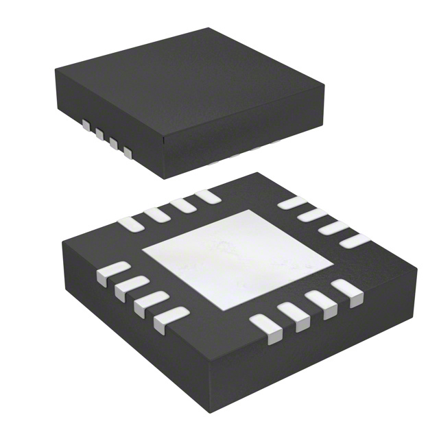
Pin Configurations
12
11
10
9
9
EN 13
I.C. 14
MAX16909
MAX16909
FSYNC 15
8
1
TSSOP
2
3
SUP
7
BST
6
GND
5
BIAS
4
TQFN
(5mm × 5mm)
COMP
7
PGOOD
PGOOD
6
GND
FOSC
5
BIAS
FSYNC
4
COMP
3
FB
2
OUT
1
EP
+
FB
FOSC 16
OUT
EP
+
8
Pin Descriptions
PIN
NAME
FUNCTION
15
FSYNC
Synchronization Input. The device synchronizes to an external signal applied to FSYNC.
The external clock frequency must be 10% greater than the internal clock frequency for
proper operation. Connect FSYNC to GND if the internal clock is used.
2
16
FOSC
Resistor-Programmable Switching-Frequency Setting Control Input. Connect a resistor
from FOSC to GND to set the switching frequency.
3
1
PGOOD
Open-Drain, Active-Low Output. PGOOD asserts when VOUT is below the 92.5% regulation point. PGOOD deasserts when VOUT is above the 95% regulation point.
4
2
OUT
Switch Regulator Output. OUT also provides power to the internal circuitry when the output voltage of the converter is set between 3V and 5V during standby mode.
5
3
FB
6
4
COMP
7
5
BIAS
Linear Regulator Output. BIAS powers up the internal circuitry. Bypass with a 1FF
capacitor to ground.
8
6
GND
Ground
9
7
BST
High-Side Driver Supply. Connect a 0.1FF capacitor between LX and BST for proper
operation.
TSSOP
TQFN
1
Maxim Integrated
Feedback Input. Connect an external resistive divider from OUT to FB and GND to set
the output voltage. Connect to BIAS to set the output voltage to 5V.
Error-Amplifier Output. Connect an RC network from COMP to GND for stable operation.
See the Compensation Network section for more details.
9
�MAX16909
36V, 220kHz to 1MHz Step-Down Converter
with Low Operating Current
Pin Descriptions (continued)
PIN
NAME
FUNCTION
TSSOP
TQFN
10
8
SUP
11, 12
9, 10
LX
13, 14
11, 12
SUPSW
15
13
EN
SUP Voltage-Compatible Enable Input. Drive EN low to disable the device. Drive EN
high to enable the device.
16
14
I.C.
Internally Connected. Connect to ground for proper operation.
—
—
EP
Exposed Pad. Connect EP to a large-area contiguous copper ground plane for effective
power dissipation. Do not use as the only IC ground connection. EP must be connected
to GND.
Voltage Supply Input. SUP powers up the internal linear regulator. Connect a minimum
4.7FF capacitor to ground.
Inductor Switching Node. Connect a Schottky diode between LX and GND.
Internal High-Side Switch-Supply Input. SUPSW provides power to the internal switch.
Connect a 0.1FF decoupling capacitor and a 4.7FF ceramic capacitor to ground.
Internal Block Diagram
OUT
FB
COMP
FBSW
PGOOD
FBOK
EN
SUP
AON
HVLDO
BIAS
SWITCHOVER
BST
SUPSW
EAMP
LOGIC
PWM
HSD
REF
LX
CS
SOFTSTART
SLOPE
COMP
OSC
FSYNC
Maxim Integrated
MAX16909
GND
FOSC
10
�MAX16909
36V, 220kHz to 1MHz Step-Down Converter
with Low Operating Current
Detailed Description
The MAX16909 is a constant-frequency, current-mode,
automotive buck converter with an integrated high-side
switch. The device operates with input voltages from 3.5V
to 36V and tolerates input transients from 3.5V up to 42V.
During undervoltage events, such as cold-crank conditions, the internal pass device maintains 98% duty cycle.
The switching frequency is resistor programmable from
220kHz to 1MHz to allow optimization for efficiency, noise,
and board space. A synchronization input FSYNC allows
the device to synchronize to an external clock frequency.
During light-load conditions, the device enters skip mode
for high efficiency. The 5V fixed output voltage eliminates
the need for external resistors and reduces the supply
current to 30FA. See the Internal Block Diagram for more
information.
Wide Input Voltage Range (3.5V to 36V)
The device includes two separate supply inputs, SUP
and SUPSW, specified for a wide 3.5V to 36V input
voltage range. VSUP provides power to the device and
VSUPSW provides power to the internal switch. When
the device is operating with a 3.5V input supply, certain
conditions such as cold crank can cause the voltage at
SUPSW to drop below the programmed output voltage.
As such, the device operates in a high duty-cycle mode
to maintain output regulation.
Linear Regulator Output (BIAS)
The device includes a 5V linear regulator, BIAS, that
provides power to the internal circuitry. Connect a 1FF
ceramic capacitor from BIAS to GND.
External Clock Input (FSYNC)
The device synchronizes to an external clock signal
applied at FSYNC. The signal at FSYNC must have a
10% higher frequency than the internal clock frequency
for proper synchronization.
Soft-Start
The device includes an 8.5ms fixed soft-start time for up
to 500FF capacitive load with a 3A resistive load.
Minimum On-Time
The device features a 110ns minimum on-time that
ensures proper operation at 1MHz switching frequency
and high differential voltage between the input and the
output. This feature is extremely beneficial in automotive applications where the board space is limited and
Maxim Integrated
the converter needs to maintain a well-regulated output
voltage using an input voltage that varies from 9V to
18V. Additionally, the device incorporates an innovative
design for fast-loop response that further ensures good
output-voltage regulation during transients.
System Enable (EN)
An enable-control input (EN) activates the device from its
low-power shutdown mode. EN is compatible with inputs
from automotive battery level down to 3.3V. The highvoltage compatibility allows EN to be connected to SUP,
KEY/KL30, or the INH pin of a CAN transceiver.
EN turns on the internal regulator. Once VBIAS is above
the internal lockout threshold, VUVL = 3.15V (typ), the
controller activates and the output voltage ramps up
within 8.5ms.
A logic-low at EN shuts down the device. During shutdown, the internal linear regulator and gate drivers turn
off. Shutdown is the lowest power state and reduces the
quiescent current to 5FA (typ). Drive EN high to bring the
device out of shutdown.
Overvoltage Protection
The device includes overvoltage protection circuitry that
protects the device when there is an overvoltage condition at the output. If the output voltage increases by more
than 110% of its set voltage, the device stops switching.
The device resumes regulation once the overvoltage
condition is removed.
Fast Load-Transient Response
Current-mode buck converters include an integrator
architecture and a load-line architecture. The integrator architecture has large loop gain but slow transient
response. The load-line architecture has fast transient
response but low loop gain. The device features an integrator architecture with innovative designs to improve
transient response. Thus, the device delivers high outputvoltage accuracy, plus the output can recover quickly
from a transient overshoot, which could damage other
on-board components during load transients.
Overload Protection
The overload protection circuitry is triggered when the
device is in current limit and VOUT is below the reset
threshold. Under these conditions the device turns the
high-side FET off for 16ms and re-enters soft-start. If the
overload condition is still present, the device repeats the
cycle.
11
�MAX16909
36V, 220kHz to 1MHz Step-Down Converter
with Low Operating Current
Skip Mode/Standby Mode
During light-load operation the device enters skip mode
operation. Skip mode turns off the majority of circuitry
and allows the output to drop below regulation voltage
before the switch is turned on again. The lower the load
current, the longer it takes for the regulator to initiate
a new cycle. Because the converter skips unnecessary cycles and turns off the majority of circuitry, the
converter efficiency increases. When the high-side FET
stops switching for more than 50Fs, most of the internal
circuitry, including LDO, draws power from VOUT (VOUT
= 3V to 5.5V), allowing current consumption from the battery to drop to only 30FA.
Overtemperature Protection
Thermal-overload protection limits the total power dissipation in the device. When the junction temperature
exceeds +175NC (typ), an internal thermal sensor
shuts down the internal bias regulator and the stepVOUT
RFB1
MAX16909
FB
RFB2
Figure 1. Adjustable Output-Voltage Setting
SWITCHING FREQUENCY vs. RFOSC
MAX16909 toc05
1.0
SWITCHING FREQUENCY (MHz)
0.9
0.8
0.7
0.6
Applications Information
Setting the Output Voltage
Connect FB to BIAS for a fixed 5V output voltage. To set
the output to other voltages between 1V and 10V, connect a resistive divider from output (OUT) to FB to GND
(Figure 1). Calculate RFB1 (OUT to FB resistor) with the
following equation:
V
=
R FB1 R FB2 OUT − 1
VFB
where VFB = 1V (see the Electrical Characteristics table).
Internal Oscillator
The switching frequency, fSW, is set by a resistor (RFOSC)
connected from FOSC to GND. See Figure 2 to select the
correct RFOSC value for the desired switching frequency.
For example, a 400kHz switching frequency is set with
RFOSC = 65kI. Higher frequencies allow designs with
lower inductor values and less output capacitance.
Consequently, peak currents and I2R losses are lower
at higher switching frequencies, but core losses, gate
charge currents, and switching losses increase.
Inductor Selection
Three key inductor parameters must be specified for
operation with the device: inductance value (L), inductor
saturation current (ISAT), and DC resistance (RDCR). To
select inductance value, the ratio of inductor peak-topeak AC current to DC average current (LIR) must be
selected first. A good compromise between size and loss
is a 30% peak-to-peak ripple current to average-current
ratio (LIR = 0.3). The switching frequency, input voltage,
output voltage, and selected LIR then determine the
inductor value as follows:
V
(V
− VOUT )
L = OUT SUP
VSUP fSWI OUTLIR
0.5
0.4
0.3
0.2
VIN = 14V
0.1
0
20
30
40
50
60
70
80
RFOSC (kI)
Figure 2. Switching Frequency vs. RFOSC
Maxim Integrated
down converter, allowing the IC to cool. The thermal
sensor turns on the IC again after the junction temperature cools by 15NC.
90 100 110
where VSUP, VOUT, and IOUT are typical values (so that
efficiency is optimum for typical conditions). The switching frequency is set by RFOSC (see the Internal Oscillator
section). The exact inductor value is not critical and can
be adjusted to make trade-offs among size, cost, efficiency, and transient response requirements. Table 1 shows
a comparison between small and large inductor sizes.
12
�MAX16909
36V, 220kHz to 1MHz Step-Down Converter
with Low Operating Current
Table 1. Inductor Size Comparison
INDUCTOR SIZE
SMALLER
LARGER
Lower price
Smaller ripple
Smaller form factor
Higher efficiency
Faster load response
Larger fixed-frequency
range in skip mode
The inductor value must be chosen so that the maximum
inductor current does not reach the device’s minimum
current limit. The optimum operating point is usually
found between 25% and 35% ripple current. When pulse
skipping (FSYNC low and light loads), the inductor value
also determines the load-current value at which PFM/
PWM switchover occurs.
Find a low-loss inductor having the lowest possible
DC resistance that fits in the allotted dimensions. Most
inductor manufacturers provide inductors in standard
values, such as 1.0FH, 1.5FH, 2.2FH, 3.3FH, etc. Also
look for nonstandard values, which can provide a better compromise in LIR across the input voltage range. If
using a swinging inductor (where the no-load inductance
decreases linearly with increasing current), evaluate
the LIR with properly scaled inductance values. For
the selected inductance value, the actual peak-to-peak
inductor ripple current (DIINDUCTOR) is defined by:
VOUT (VSUP − VOUT )
∆IINDUCTOR =
VSUP × fSW × L
where DIINDUCTOR is in A, L is in H, and fSW is in Hz.
Ferrite cores are often the best choices, although powdered iron is inexpensive and can work well at 200kHz.
The core must be large enough not to saturate at the
peak inductor current (IPEAK):
∆I
=
IPEAK ILOAD(MAX) + INDUCTOR
2
Input Capacitor
The input filter capacitor reduces peak currents drawn
from the power source and reduces noise and voltage
ripple on the input caused by the circuit’s switching.
The input capacitor RMS current requirement (IRMS) is
defined by the following equation:
IRMS = ILOAD(MAX)
Maxim Integrated
VOUT (VSUP − VOUT )
VSUP
IRMS has a maximum value when the input voltage
equals twice the output voltage (VSUP = 2VOUT), so
IRMS(MAX) = ILOAD(MAX)/2.
Choose an input capacitor that exhibits less than +10NC
self-heating temperature rise at the RMS input current for
optimal long-term reliability.
The input-voltage ripple is composed of DVQ (caused
by the capacitor discharge) and DVESR (caused by the
equivalent series resistance (ESR) of the capacitor). Use
low-ESR ceramic capacitors with high ripple-current
capability at the input. Assume the contribution from the
ESR and capacitor discharge equal to 50%. Calculate
the input capacitance and ESR required for a specified
input-voltage ripple using the following equations:
∆VESR
ESRIN =
∆I
I OUT + L
2
where
and
(V
− VOUT ) × VOUT
∆IL = SUP
VSUP × fSW × L
I
× D(1 − D)
VOUT
CIN = OUT
and D =
VSUPSW
∆VQ × fSW
where IOUT is the maximum output current, and D is the
duty cycle.
Output Capacitor
The output filter capacitor must have low enough ESR to
meet output ripple and load-transient requirements, yet
have high enough ESR to satisfy stability requirements.
The output capacitance must be high enough to absorb
the inductor energy while transitioning from full-load
to no-load conditions without tripping the overvoltage
fault protection. When using high-capacitance, low-ESR
capacitors, the filter capacitor’s ESR dominates the
output-voltage ripple. So the size of the output capacitor depends on the maximum ESR required to meet the
output-voltage ripple (VRIPPLE(P-P)) specifications:
VRIPPLE(P-P) = ESR × ILOAD(MAX) × LIR
The actual capacitance value required relates to the
physical size needed to achieve low ESR, as well as
to the chemistry of the capacitor technology. Thus, the
capacitor is usually selected by ESR and voltage rating
rather than by capacitance value.
13
�MAX16909
36V, 220kHz to 1MHz Step-Down Converter
with Low Operating Current
When using low-capacity filter capacitors, such as
ceramic capacitors, size is usually determined by the
capacity needed to prevent voltage droop and voltage rise from causing problems during load transients.
Generally, once enough capacitance is added to meet
the overshoot requirement, undershoot at the rising load
edge is no longer a problem. However, low-capacity filter
capacitors typically have high-ESR zeros that can affect
the overall stability.
Rectifier Selection
The device requires an external Schottky diode rectifier as a freewheeling diode. Connect this rectifier close
to the device using short leads and short PCB traces.
Choose a rectifier with a voltage rating greater than the
maximum expected input voltage, VSUPSW. Use a low
forward-voltage-drop Schottky rectifier to limit the negative voltage at LX. Avoid higher than necessary reversevoltage Schottky rectifiers that have higher forwardvoltage drops.
Compensation Network
The device uses an internal transconductance error
amplifier with its inverting input and its output available
to the user for external frequency compensation. The
output capacitor and compensation network determine
the loop stability. The inductor and the output capacitor are chosen based on performance, size, and cost.
Additionally, the compensation network optimizes the
control-loop stability.
The controller uses a current-mode control scheme that
regulates the output voltage by forcing the required current
through the external inductor. The device uses the voltage drop across the high-side MOSFET to sense inductor
The basic regulator loop is modeled as a power modulator, output feedback divider, and an error amplifier. The
power modulator has a DC gain set by gmc x RLOAD,
with a pole and zero pair set by RLOAD, the output
capacitor (COUT), and its ESR. The following equations
allow to approximate the value for the gain of the power
modulator (GAINMOD(DC)), neglecting the effect of the
ramp stabilization. Ramp stabilization is necessary when
the duty cycle is above 50% and is internally done for
the device.
GAINMOD(DC)
= g mc × R LOAD
where RLOAD = VOUT/ILOUT(MAX) in I, fSW is the switching frequency in MHz, L is the output inductance in H,
and gmc = 3S.
In a current-mode step-down converter, the output
capacitor, its ESR, and the load resistance introduce a
pole at the following frequency:
fpMOD =
VOUT
1
2π × C OUT × (R LOAD + ESR)
The output capacitor and its ESR also introduce a zero at:
R1
R2
current. Current-mode control eliminates the double pole
in the feedback loop caused by the inductor and output
capacitor, resulting in a smaller phase shift and requiring
less elaborate error-amplifier compensation than voltagemode control. Only a simple single-series resistor (RC)
and capacitor (CC) are required to have a stable, highbandwidth loop in applications where ceramic capacitors
are used for output filtering (Figure 3). For other types of
capacitors, due to the higher capacitance and ESR, the
frequency of the zero created by the capacitance and
ESR is lower than the desired closed-loop crossover frequency. To stabilize a nonceramic output capacitor loop,
add another compensation capacitor (CF) from COMP to
GND to cancel this ESR zero.
gm
VREF
fzMOD =
COMP
RC
CC
CF
1
2π × ESR × C OUT
When COUT is composed of “n” identical capacitors
in parallel, the resulting COUT = n x COUT(EACH) and
ESR = ESR(EACH)/n. Note that the capacitor zero for a
parallel combination of alike capacitors is the same as
for an individual capacitor.
Figure 3. Compensation Network
Maxim Integrated
14
�MAX16909
36V, 220kHz to 1MHz Step-Down Converter
with Low Operating Current
The feedback voltage-divider has a gain of GAINFB =
VFB/VOUT, where VFB is 1V (typ).
The transconductance error amplifier has a DC gain of
GAINEA(DC) = gm,EA x ROUT,EA, where gm,EA is the erroramplifier transconductance, which is 900FS (typ), and
ROUT,EA is the output resistance of the error amplifier.
A dominant pole (fdpEA) is set by the compensation capacitor (CC) and the amplifier output resistance
(ROUT,EA). A zero (fzEA) is set by the compensation
resistor (RC) and the compensation capacitor (CC).
There is an optional pole (fpEA) set by CF and RC to
cancel the output capacitor ESR zero if it occurs near
the crossover frequency (fC, where the loop gain equals
1 (0dB)). Thus:
1
fdpEA =
2π × C C × (R OUT,EA + R C )
fzEA =
The total loop gain as the product of the modulator gain,
the feedback voltage-divider gain, and the error-amplifier
gain at fC should be equal to 1. So:
VFB
× GAINEA(fC) =
1
VOUT
For the case where fzMOD is greater than fC:
GAINEA(fC) = gm,EA × RC
GAINMOD(fC) ×
Solving for RC:
RC =
Maxim Integrated
fpMOD
fzMOD
The error-amplifier gain at fC is:
f
GAINEA(fC)= g m,EA × R C × zMOD
fC
Therefore:
f
fpMOD


 工商网监
湘ICP备2023018690号
工商网监
湘ICP备2023018690号
