EVALUATION KIT AVAILABLE
MAX16932/MAX16933
General Description
The MAX16932/MAX16933 offer two high-voltage,
synchronous step-down controllers that use only 20µA of
quiescent current with no load. They operate with an input
voltage supply from 3.5V to 42V and can operate in dropout condition by running at 95% duty cycle. The devices
are intended for applications with mid- to high-power
requirements and requiring two independently controlled
output supplies, such as automotive applications.
The MAX16932/MAX16933 step-down controllers operate 180° out-of-phase for reduced input ripple. The
devices also operate with switching frequencies up to
2.2MHz to allow use of small external components and
to guarantee no AM band interference. The FSYNC input
programmability enables three frequency modes for optimized performance: forced fixed-frequency operation,
skip mode with ultra-low quiescent current (20µA), and
synchronization to an external clock. The devices provide
a spread-spectrum option to minimize EMI interference.
2.2MHz, 36V, Dual Buck
with 20µA Quiescent Current
Benefits and Features
●● Meets Stringent OEM Module Power Consumption
and Performance Specifications
• 20µA Quiescent Current in Skip Mode
• ±1% Output-Voltage Accuracy: 5.0V/3.3V Fixed or
Adjustable Between 1V and 10V
●● Enables Crank-Ready Designs
• Wide Input Supply Range from 3.5V to 36V
●● EMI Reduction Features Reduce Interference with
Sensitive Radio Bands without Sacrificing Wide Input
Voltage Range
• 50ns (typ) Minimum On-Time Guarantees SkipFree Operation for 3.3V Output from Car Battery
at 2.2MHz
• Spread-Spectrum Option
• Frequency-Synchronization Input
• Resistor-Programmable Frequency Between
200kHz and 2.2MHz
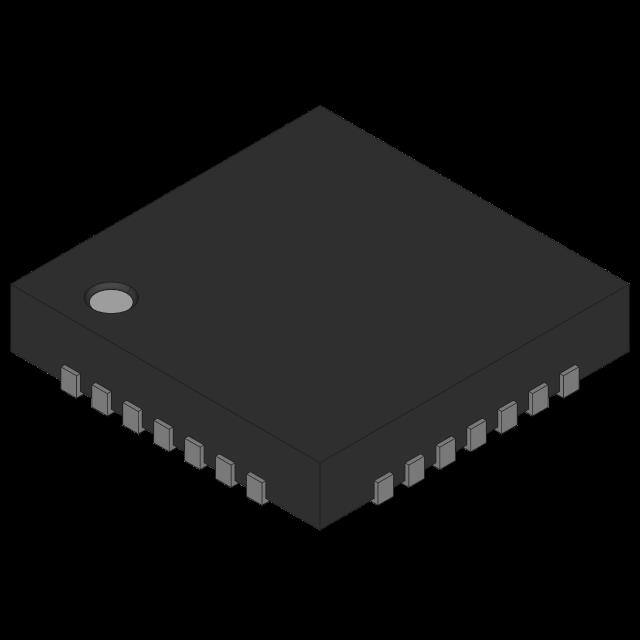
The devices are available in a 28-pin TQFN-EP package
and are specified for operation over the -40°C to +125°C
automotive temperature range.
●● Integration and Thermally Enhanced Packages Save
Board Space and Cost
• Dual, 2MHz Step-Down Controllers
• 180° Out-of-Phase Operation
• Current-Mode Controllers with Forced-Continuous
and Skip Modes
• Thermally Enhanced 28-Pin TQFN-EP Package
Ordering Information and Selector Guide appears at end of
data sheet.
●● Protection Features Improve System Reliability
• Supply Overvoltage and Undervoltage Lockout
• Overtemperature and Short-Circuit Protection
The devices also feature a power-OK monitor and overvoltage and undervoltage lockout. Protection features
include cycle-by-cycle current limit and thermal shutdown.
Applications
●● POL Applications for Automotive Power
●● Distributed DC Power Systems
●● Navigation and Radio Head Units
19-6716; Rev 10; 9/17
�MAX16932/MAX16933
2.2MHz, 36V, Dual Buck
with 20µA Quiescent Current
Absolute Maximum Ratings
IN, EN1, EN2, TERM to PGND_............................-0.3V to +42V
CS1, CS2, OUT1, OUT2 to AGND......................... -0.3V to +11V
CS1 to OUT1.........................................................-0.2V to +0.2V
CS2 to OUT2.........................................................-0.2V to +0.2V
BIAS, FSYNC, FOSC to AGND............................-0.3V to +6.0V
COMP1, COMP2 to AGND...................................-0.3V to +6.0V
FB1, FB2, EXTVCC to AGND...............................-0.3V to +6.0V
DL_ to PGND_......................................................-0.3V to +6.0V
BST_, to LX_.........................................................-0.3V to +6.0V
DH_ to LX_............................................................-0.3V to +6.0V
LX_ to PGND_.......................................................-0.3V to +42V
PGND_ to AGND...................................................-0.3V to +0.3V
PGOOD1, PGOOD2 to AGND..............................-0.3V to +6.0V
Continuous Power Dissipation (TA = +70°C)
TQFN (derate 28.6mW/NC above +70°C)..............2285.7mW
Operating Temperature Range.......................... -40°C to +125°C
Junction Temperature Range...........................................+150°C
Storage Temperature Range............................. -65°C to +150°C
Lead Temperature (soldering, 10s).................................. +300°C
Soldering Temperature (reflow)........................................ +260°C
Stresses beyond those listed under “Absolute Maximum Ratings” may cause permanent damage to the device. These are stress ratings only, and functional operation of the device at these
or any other conditions beyond those indicated in the operational sections of the specifications is not implied. Exposure to absolute maximum rating conditions for extended periods may affect
device reliability.
Package Thermal Characteristics (Note 1)
TQFN
Junction-to-Ambient Thermal Resistance (θJA)...........35°C/W
Junction-to-Case Thermal Resistance (θJC)..................3°C/W
Note 1: Package thermal resistances were obtained using the method described in JEDEC specification JESD51-7, using a four-layer
board. For detailed information on package thermal considerations, refer to www.maximintegrated.com/thermal-tutorial.
Electrical Characteristics
(VIN = 14V, VBIAS = 5V, CBIAS = 6.8µF, TA = TJ = -40°C to +125°C, unless otherwise noted. Typical values are at TA = +25°C under
normal conditions, unless otherwise noted.) (Note 2)
PARAMETER
SYMBOL
CONDITIONS
MIN
TYP
MAX
UNIT
SYNCHRONOUS STEP-DOWN DC-DC CONTROLLERS
Supply Voltage Range
VIN
Output Overvoltage Threshold
Supply Current
IIN
Buck 1 Fixed Output Voltage
VOUT1
Buck 2 Fixed Output Voltage
VOUT2
Output Voltage Adjustable Range
www.maximintegrated.com
Normal operation
3.5
36
t < 1s
42
FB rising (Note 3)
+10
+15
+20
FB falling
+5
+10
+15
VEN1 = VEN2 = 0V, TA = +25°C
8
20
VEN1 = VEN2 = 0V, TA = +125°C
20
VEN1 = 5V, VOUT1 = 5V, VEN2 = 0V;
VEXTVCC = 5V, no switching
30
40
VEN2 = 5V, VOUT2 = 3.3V; VEN1 = 0V,
VEXTVCC = 3.3V, no switching
20
30
VEN1 = VEN2 = 5V, VOUT1 = 5V, VOUT2 =
3.3V, VEXTVCC = 3.3V, no switching
25
40
VFB1 = VBIAS, PWM mode
4.95
5
5.05
VFB1 = VBIAS, skip mode
4.95
5
5.075
VFB2 = VBIAS, PWM mode
3.234
3.3
3.366
VFB2 = VBIAS, skip mode
3.234
3.3
3.4
Buck 1, buck 2
1
10
V
%
µA
V
V
V
Maxim Integrated │ 2
�MAX16932/MAX16933
2.2MHz, 36V, Dual Buck
with 20µA Quiescent Current
Electrical Characteristics (continued)
(VIN = 14V, VBIAS = 5V, CBIAS = 6.8µF, TA = TJ = -40°C to +125°C, unless otherwise noted. Typical values are at TA = +25°C under
normal conditions, unless otherwise noted.) (Note 2)
PARAMETER
SYMBOL
Regulated Feedback Voltage
VFB1,2
Feedback Leakage Current
IFB1,2
Feedback Line Regulation Error
Transconductance
(from FB_ to COMP_)
gm
Dead Time
Maximum Duty Cycle
Minimum On-Time
PWM Switching Frequency
CONDITIONS
0.99
fSW
Switching Frequency Accuracy
Spread-Spectrum Range
MAX
UNIT
1.0
1.01
V
0.01
1
µA
VIN = 3.5V to 36V, VFB = 1V
0.001
VFB = 1V, VBIAS = 5V
1200
MAX16932: DL_ low to DH_ high
35
MAX16932: DH_ low to DL_ high
60
MAX16933: DL_ low to DH_ high
60
MAX16933: DH_ low to DL_ high
100
95
Buck 1, buck 2
%/V
2400
µS
ns
98.5
%
50
ns
MAX16932
1
2.2
MAX16933
0.2
1
MAX16932ATIT/V+,
MAX16932CATIU/V+ only
Buck 2 Switching Frequency
TYP
TA = +25°C
Buck 1, buck 2
tON(MIN)
MIN
1/2fSW
MHz
MHz
MAX16932: RFOSC = 13.7kΩ,
VBIAS = 5V
1.98
2.2
2.42
MHz
MAX16933: RFOSC = 80.6kΩ,
VBIAS = 5V
360
400
440
kHz
Spread spectrum enabled
±6
%
FSYNC INPUT
FSYNC Frequency Range
FSYNC Switching Thresholds
CS Current-Limit Voltage
Threshold
MAX16932: Minimum sync pulse of 100ns
1.2
2.4
MHz
MAX16933: Minimum sync pulse of 400ns
240
1200
kHz
High threshold
1.5
Low threshold
VLIMIT1,2
VCS – VOUT, VBIAS = 5V, VOUT ≥ 2.5V
0.6
64
Skip Mode Threshold
Soft-Start Ramp Time
80
96
15
Buck 1 and buck 2, fixed soft-start time
regardless of frequency
Phase Shift Between Buck1 and
Buck 2
2
6
V
mV
mV
10
ms
180
°
0.01
µA
LX1, LX2 Leakage Current
VIN = 6V, VLX_ = VIN, TA = +25°C
DH1, DH2 Pullup Resistance
VBIAS = 5V, IDH_ = -100mA
10
20
Ω
DH1, DH2 Pulldown Resistance
VBIAS = 5V, IDH_ = +100mA
2
4
Ω
DL1, DL2 Pullup Resistance
VBIAS = 5V, IDL_ = -100mA
4
8
Ω
DL1, DL2 Pulldown Resistance
VBIAS = 5V, IDL_ = +100mA
1.5
3
Ω
www.maximintegrated.com
Maxim Integrated │ 3
�MAX16932/MAX16933
2.2MHz, 36V, Dual Buck
with 20µA Quiescent Current
Electrical Characteristics (continued)
(VIN = 14V, VBIAS = 5V, CBIAS = 6.8µF, TA = TJ = -40°C to +125°C, unless otherwise noted. Typical values are at TA = +25°C under
normal conditions, unless otherwise noted.) (Note 2)
PARAMETER
PGOOD1, PGOOD2 Threshold
SYMBOL
CONDITIONS
MIN
TYP
MAX
PGOOD_H
% of VOUT_, rising
85
90
95
PGOOD_F
% of VOUT_, falling
80
85
90
0.01
1
PGOOD1, PGOOD2 Leakage
Current
VPGOOD1,2 = 5V, TA = +25°C
PGOOD1, PGOOD2 Startup
Delay Time
Buck 1 and buck 2 after soft-start
is complete
PGOOD1, PGOOD2 Debounce
Time
Fault detection
64
UNIT
%
µA
Cycles
8
20
50
µs
4.75
5
5.25
V
3.1
3.4
INTERNAL LDO: BIAS
Internal BIAS Voltage
VIN > 6V
VBIAS rising
BIAS UVLO Threshold
VBIAS falling
2.7
Hysteresis
External VCC
2.9
0.2
VTH,EXTVCC
EXTVCC rising, HYST = 110mV
3.0
V
V
3.2
V
THERMAL OVERLOAD
Thermal Shutdown Temperature
(Note 4)
+170
°C
Thermal Shutdown Hysteresis
(Note 4)
20
°C
EN LOGIC INPUT
High Threshold
1.8
Low Threshold
Input Current
TA = +25°C
V
0.8
V
1
µA
Note 2: Limits are 100% production tested at TA = +25°C. Limits over the operating temperature range and relevant supply voltage
range are guaranteed by design and characterization. Typical values are at TA = +25°C.
Note 3: Overvoltage protection is detected at the FB1/FB2 pins. If the feedback voltage reaches overvoltage threshold of FB1/FB2 +
15% (typ), the corresponding controller stops switching. The controllers resume switching once the output drops below FB1/
FB2 + 10% (typ).
Note 4: Guaranteed by design; not production tested.
www.maximintegrated.com
Maxim Integrated │ 4
�MAX16932/MAX16933
2.2MHz, 36V, Dual Buck
with 20µA Quiescent Current
Typical Operating Characteristics
(TA = +25°C, unless otherwise noted.)
NO LOAD STARTUP SEQUENCE
(VFSYNC = 0V)
FULL LOAD STARTUP SEQUENCE
(VFSYNC = 0V)
MAX16932 toc01
MAX16932 toc02
VBAT
5V/div
VBAT
5V/div
VOUT1
2V/div
IOUT1
2A/div
VPGOOD1
5V/div
VOUT1
2V/div
VOUT2
2V/div
VOUT2
2V/div
IOUT2
2A/div
VPGOOD2
5V/div
VPGOOD1
5V/div
VPGOOD2
5V/div
QUIESCIENT CURRENT
vs. SUPPLY VOLTAGE
30
20
VEN1 = 0V
VEN2 = VBAT
EXTVCC = VOUT2
100
90
EFFICIENCY (%)
80
70
60
50
BUCK1 EFFICIENCY
50
40
30
20
EXTVCC
= VOUT2
EXTVCC
= GND
PWM MODE
10
0
1.0E-04
1.0E-02
1.0E+00
1.0E-06
1.0E-05
1.0E-03
1.0E-01
1.0E+01
IOUT1 (A)
www.maximintegrated.com
BUCK 1
EXTVCC = VOUT1
40
30
20
0
-60 -40 -20 0 20 40 60 80 100 120 140
TEMPERATURE (°C)
fSW = 2.2MHz EXTVCC = VOUT1
L = 2.2µH
VBAT = 14V
VOUT1 = 5V
EXTVCC
= GND
SKIP MODE
MAX16932 toc04
60
BUCK 2
EXTVCC = VOUT2
10
MAX16932 toc05
0
70
100
90
80
70
60
0
5
10 15 20 25 30
SUPPLY VOLTAGE (V)
30
20
40
BUCK2 EFFICIENCY
fSW = 2.2MHz EXTVCC = VOUT2
L = 2.2µH
VBAT = 14V
VOUT2 = 3.3V
EXTVCC
= GND
SKIP MODE
50
40
35
MAX16932 toc06
VEN1 = VBAT
VEN2 = 0V
EXTVCC = VOUT1
10
80
SUPPLY CURRENT (µA)
40
QUIESCIENT CURRENT
vs. TEMPERATURE
EFFICIENCY (%)
SUPPLY CURRENT (µA)
50
4ms/div
MAX16932 toc03
60
2ms/div
EXTVCC
= GND
EXTVCC
= VOUT2
PWM MODE
10
0
1.0E-04
1.0E-02
1.0E+00
1.0E-06
1.0E-05
1.0E-03
1.0E-01
1.0E+01
IOUT2 (A)
Maxim Integrated │ 5
�MAX16932/MAX16933
2.2MHz, 36V, Dual Buck
with 20µA Quiescent Current
Typical Operating Characteristics (continued)
(TA = +25°C, unless otherwise noted.)
2.22
BUCK 1
2.20
2.18
2.16
2.14
2.12
2.10
0
1
2
3
4
5
2.0
1.8
VBIAS = 5V
1.6
1.4
VBIAS = 3.3V
1.2
15
0
LOAD CURRENT (A)
0.9
0.8
0.7
0.6
VBIAS = 5V
0.5
0.4
VBIAS = 3.3V
25
30
0.2
30
40
50
60
RFOSC = 13.7kΩ
2.30
70
90 110 130 150 170
80 100 120 140 160
RFOSC (kΩ)
LOAD TRANSIENT RESPONSE
MAX16932 toc11
MAX16932 toc10
SWITCHING FREQUENCY (MHz)
2.35
20
RFOSC (kΩ)
SWITCHING FREQUENCY vs. TEMPERATURE
2.40
1.0
0.3
0
6
MAX16932 toc09
2.2
SWITCHING FREQUENCY
vs. RFOSC (MAX16933)
1.1
SWITCHING FREQUENCY (MHz)
2.24
MAX16932 toc08
BUCK 2
2.26
2.4
SWITCHING FREQUENCY (MHz)
2.28
MAX16932 toc07
2.30
SWITCHING FREQUENCY (MHz)
SWITCHING FREQUENCY
vs. RFOSC (MAX16932)
SWITCHING FREQUENCY
vs. LOAD CURRENT
VOUT1
100mV/div
2.25
2.20
2.15
2.10
IOUT1
1A/div
2.05
2.00
-60 -40 -20 0 20 40 60 80 100 120 140
TEMPERATURE (°C)
400µs/div
EXTERNAL SYNC TRANSITION
DIPS AND DROPS
MAX16932 toc12
VLX1
10V/div
VBAT
10V/div
VLX2
10V/div
VPGOOD1
5V/div
VSYNC
2V/div
400ns/div
www.maximintegrated.com
MAX16932 toc13
VOUT1
5V/div
40ms/div
Maxim Integrated │ 6
�MAX16932/MAX16933
2.2MHz, 36V, Dual Buck
with 20µA Quiescent Current
Typical Operating Characteristics (continued)
(TA = +25°C, unless otherwise noted.)
LOAD DUMP
SLOW VIN RAMP
MAX16932 toc14
MAX16932 toc15
VBAT
5V/div
VBAT
10V/div
VOUT2
1V/div
VOUT1
2V/div
VPGOOD1
5V/div
VOUT2
2V/div
VPGOOD2
5V/div
VPGOOD2
5V/div
100ms/div
10s/div
OUTPUT OVERVOLTAGE RESPONSE
SHORT CIRCUIT RESPONSE
MAX16932 toc17
MAX16932 toc16
VOUT1
1V/div
VPGOOD1
2V/div
IOUT1
2A/div
VOUT1
1V/div
VPGOOD1
2V/div
200µs/div
1s/div
3.295
VOUT (V)
VOUT (V)
4.995
4.994
4.993
4.992
4.991
4.990
4.989
VSYNC = VBIAS
0
1
2
3
IOUT (A)
www.maximintegrated.com
4
5
6
100.05
100.00
VOUT (%NOMINAL)
4.996
VSYNC = VBIAS
3.296
100.10
3.294
3.293
3.292
99.95
3.290
99.75
1
2
3
IOUT (A)
4
5
6
VOUT1
99.85
99.80
0
VOUT2
99.90
3.291
3.289
MAX16932 toc20
MAX16932 toc18
VSYNC = VBIAS
4.997
VOUT vs. TEMPERATURE
BUCK 2 LOAD REGULATION
3.297
MAX16932 toc19
BUCK 1 LOAD REGULATION
4.998
99.70
EXTVCC = VGND
VSYNC = VBIAS
IOUT_ = 0A
-60 -40 -20 0 20 40 60 80 100 120 140
TEMPERATURE (°C)
Maxim Integrated │ 7
�MAX16932/MAX16933
2.2MHz, 36V, Dual Buck
with 20µA Quiescent Current
Typical Operating Characteristics (continued)
(TA = +25°C, unless otherwise noted.)
MAX16932 toc21
VOUT1 = 1.8V
1.000
0.995
1.000
0.995
0
10
5
15 20 25
VSUP (V)
30
35
0.990
40
0
MINIMUM ON-TIME (BUCK 1)
10
5
15 20 25
VSUP (V)
IOUT2 = 300mA
VBAT
5V/div
VBAT
5V/div
VOUT1
1V/div
VOUT1
1V/div
200ns/div
20
10
0
30
MEASURED AT VOUT2 ON THE
MAX16932CATIU/V+
25
20
15
10
5
0
500,000
-10
800k
30
SPECTRAL ENERGY DENSITY
vs. FREQUENCY
MEASURED ON THE
MAX16932CATIS/V+
25
20
15
10
5
0
-5
-5
350,000 400,000 450,000
FREQUENCY (Hz)
35
OUTPUT SPECTRUM (dBµV)
30
35
SPECTRAL ENERGY DENSITY
vs. FREQUENCY
MAX16932 toc26
40
40
OUTPUT SPECTRUM (dBµV)
MEASURED ON THE MAX16933CATIS/V+
MAX16932 toc25
OUTPUT SPECTRUM (dBµV)
200ns/div
SPECTRAL ENERGY DENSITY
vs. FREQUENCY
www.maximintegrated.com
40
MAX16932 toc24
IOUT1 = 300mA
-10
300,000
35
MINIMUM ON-TIME (BUCK 2)
MAX16932 toc23
50
30
MAX16932 toc27
0.990
VOUT2 = 1.8V
1.005
VOUT (V)
VOUT (V)
1.005
FB2 LINE REGULATION
1.010
MAX16932 toc22
FB1 LINE REGULATION
1.010
900k
1000k
1100k
FREQUENCY (Hz)
1200k
-10
1800k
2200k
2400k
2000k
FREQUENCY (Hz)
2600k
Maxim Integrated │ 8
�MAX16932/MAX16933
2.2MHz, 36V, Dual Buck
with 20µA Quiescent Current
FB2
COMP2
FOSC
20
CS2
21
OUT2
PGND2
TOP VIEW
DL2
Pin Configuration
19
18
17
16
15
LX2 22
14
FSYNC
DH2 23
13
PGOOD2
12
PGOOD1
11
IN
EN1 26
10
EXTVCC
BST1 27
9
AGND
8
BIAS
MAX16932
MAX16933
BST2 24
EN2 25
EP
5
6
7
COMP1
4
FB1
LX1
DL1
3
OUT1
2
CS1
1
PGND1
+
DH1 28
TQFN
(5mm x 5mm)
Pin Description
PIN
NAME
1
LX1
Inductor Connection for Buck 1. Connect LX1 to the switched side of the inductor. LX1 serves as the
lower supply rail for the DH1 high-side gate drive.
2
DL1
Low-Side Gate Drive Output for Buck 1. DL1 output voltage swings from VPGND1 to VBIAS.
3
PGND1
4
CS1
5
OUT1
6
FB1
7
COMP1
8
BIAS
9
AGND
www.maximintegrated.com
DESCRIPTION
Power Ground for Buck 1
Positive Current-Sense Input for Buck 1. Connect CS1 to the positive terminal of the current-sense
resistor. See the Current Limiting and Current-Sense Inputs and Current-Sense Measurement
sections.
Output Sense and Negative Current-Sense Input for Buck 1. When using the internal preset 5V
feedback divider (FB1 = BIAS), the buck uses OUT1 to sense the output voltage. Connect OUT1 to
the negative terminal of the current-sense resistor. See the Current Limiting and Current-Sense Inputs
and Current-Sense Measurement sections.
Feedback Input for Buck 1. Connect FB1 to BIAS for the 5V fixed output or to a resistive divider
between OUT1 and GND to adjust the output voltage between 1V and 10V. In adjustable mode,
FB1 regulates to 1V (typ). See the Setting the Output Voltage in Buck Converters section.
Buck 1 Error-Amplifier Output. Connect an RC network to COMP1 to compensate buck 1.
5V Internal Linear Regulator Output. Bypass BIAS to GND with a low-ESR ceramic capacitor of 6.8µF
minimum value. BIAS provides the power to the internal circuitry and external loads. See the Fixed 5V
Linear Regulator (BIAS) section.
Signal Ground for IC
Maxim Integrated │ 9
�MAX16932/MAX16933
2.2MHz, 36V, Dual Buck
with 20µA Quiescent Current
Pin Description (continued)
PIN
NAME
10
EXTVCC
11
IN
Supply Input. Bypass IN with sufficient capacitance to supply the two out-of-phase buck converters.
PGOOD1
Open-Drain Power-Good Output for Buck 1. PGOOD1 is low if OUT1 is more than 15% (typ) below
the normal regulation point. PGOOD1 asserts low during soft-start and in shutdown. PGOOD1
becomes high impedance when OUT1 is in regulation. To obtain a logic signal, pullup PGOOD1
with an external resistor connected to a positive voltage lower than 5.5V. Place a minimum of 100Ω
(RPGOOD1) in series with PGOOD1. See the Voltage Monitoring section for details.
13
PGOOD2
Open-Drain Power-Good Output for Buck 2. PGOOD2 is low if OUT2 is more than 15% (typ) below
the normal regulation point. PGOOD2 asserts low during soft-start and in shutdown. PGOOD2
becomes high impedance when OUT2 is in regulation. To obtain a logic signal, pullup PGOOD2 with
an external resistor connected to a positive voltage lower than 5.5V.
14
FSYNC
External Clock Synchronization Input. Synchronization to the controller operating frequency ratio is
1. Keep fSYNC a minimum of 10% greater than the maximum internal switching frequency for stable
operation. See the Switching Frequency/External Synchronization section.
15
FOSC
Frequency Setting Input. Connect a resistor from FOSC to AGND to set the switching frequency of
the DC-DC converters.
16
COMP2
17
FB2
12
DESCRIPTION
3.1V to 5.2V Input to the Switchover Comparator
Buck 2 Error Amplifier Output. Connect an RC network to COMP2 to compensate buck 2.
Feedback Input for Buck 2. Connect FB2 to BIAS for the 3.3V fixed output or to a resistive divider
between OUT2 and GND to adjust the output voltage between 1V and 10V. In adjustable mode, FB2
regulates to 1V (typ). See the Setting the Output Voltage in Buck Converters section.
Output Sense and Negative Current-Sense Input for Buck 2. When using the internal preset 3.3V
feedback-divider (FB2 = BIAS), the buck uses OUT2 to sense the output voltage. Connect OUT2 to
the negative terminal of the current-sense resistor. See the Current Limiting and Current-Sense Inputs
and Current-Sense Measurement sections.
18
OUT2
19
CS2
20
PGND2
21
DL2
Low-Side Gate Drive Output for Buck 2. DL2 output voltage swings from VPGND2 to VBIAS.
22
LX2
Inductor Connection for Buck 2. Connect LX2 to the switched side of the inductor. LX2 serves as the
lower supply rail for the DH2 high-side gate drive.
23
DH2
High-Side Gate Drive Output for Buck 2. DH2 output voltage swings from VLX2 to VBST2.
24
BST2
Boost Capacitor Connection for High-Side Gate Voltage of Buck 2. Connect a high-voltage diode
between BIAS and BST2. Connect a ceramic capacitor between BST2 and LX2. See the High-Side
Gate-Driver Supply (BST_) section.
25
EN2
High-Voltage Tolerant, Active-High Digital Enable Input for Buck 2. Driving EN2 high enables
buck 2.
26
EN1
High-Voltage Tolerant, Active-High Digital Enable Input for Buck 1. Driving EN1 high enables
buck 1.
www.maximintegrated.com
Positive Current-Sense Input for Buck 2. Connect CS2 to the positive terminal of the current-sense
resistor. See the Current Limiting and Current-Sense Inputs and Current-Sense Measurement
sections.
Power Ground for Buck 2
Maxim Integrated │ 10
�MAX16932/MAX16933
2.2MHz, 36V, Dual Buck
with 20µA Quiescent Current
Pin Description (continued)
PIN
NAME
27
BST1
Boost Capacitor Connection for High-Side Gate Voltage of Buck 1. Connect a high-voltage diode
between BIAS and BST1. Connect a ceramic capacitor between BST1 and LX1. See the High-Side
Gate-Driver Supply (BST_) section.
28
DH1
High-Side Gate-Drive Output for Buck 1. DH1 output voltage swings from VLX1 to VBST1.
—
EP
DESCRIPTION
Exposed Pad. Connect the exposed pad to ground. Connecting the exposed pad to ground does not
remove the requirement for proper ground connections to PGND1, PGND2, and AGND. The exposed
pad is attached with epoxy to the substrate of the die, making it an excellent path to remove heat from
the IC.
Detailed Description
The MAX16932/MAX16933 are automotive-rated dualoutput switching power supplies. These devices integrate
two synchronous step-down controllers and can provide
two independent controlled power rails as follows:
• A buck controller with a fixed 5V output voltage or an
adjustable 1V to 10V output voltage.
• A buck controller with a fixed 3.3V output voltage or an
adjustable 1V to 10V output voltage.
The two buck controllers can each provide up to 10A
output current and are independently controllable.
EN1 and EN2 enable the respective buck controllers.
Connect EN1 and EN2 directly to VBAT, or to powersupply sequencing logic.
In skip mode, with no load and only buck 2 active, the
total supply current is reduced to 20µA (typ). When both
controllers are disabled, the total current drawn is further
reduced to 8µA (typ).
Fixed 5V Linear Regulator (BIAS)
The internal circuitry of the MAX16932/MAX16933
requires a 5V bias supply. An internal 5V linear regulator
(BIAS) generates this bias supply. Bypass BIAS with a
6.8µF or greater ceramic capacitor to guarantee stability
under the full-load condition.
The internal linear regulator can source up to 100mA
(150mA under EXTVCC switchover, see the EXTVCC
Switchover section). Use the following equation to estimate
the internal current requirements for the MAX16932/
MAX16933:
www.maximintegrated.com
IBIAS = ICC + fSW(QG_DH1 + QG_DL1 +
QG_DH2 + QG_DL2) = 10mA to 50mA (typ)
where ICC is the internal supply current, 5mA (typ), fSW
is the switching frequency, and QG_ is the MOSFET’s
total gate charge (specification limits at VGS = 5V). To
minimize the internal power dissipation, bypass BIAS to
an external 5V rail.
EXTVCC Switchover
The internal linear regulator can be bypassed by connecting an external supply (3V to 5.2V) or the output of one of
the buck converters to EXTVCC. BIAS internally switches
to EXTVCC and the internal linear regulator turns off. This
configuration has several advantages:
• It reduces the internal power dissipation of the
MAX16932/MAX16933.
• The low-load efficiency improves as the internal supply current gets scaled down proportionally to the duty
cycle.
If VEXTVCC drops below VTH,EXTVCC = 3V (min), the
internal regulator enables and switches back to BIAS.
Undervoltage Lockout (UVLO)
The BIAS input undervoltage lockout (UVLO) circuitry
inhibits switching if the 5V bias supply (BIAS) is below
its 2.9V (typ) UVLO falling threshold. Once the 5V bias
supply (BIAS) rises above its UVLO rising threshold and
EN1 and EN2 enable the buck controllers, the controllers
start switching and the output voltages begin to ramp up
using soft-start.
Maxim Integrated │ 11
�MAX16932/MAX16933
Buck Controllers
The MAX16932/MAX16933 provide two buck controllers
with synchronous rectification. The step-down controllers use a PWM, current-mode control scheme. External
logic-level MOSFETs allow for optimized load-current
design. Fixed-frequency operation with optimal interleaving minimizes input ripple current from the minimum to the
maximum input voltages. Output-current sensing provides
an accurate current limit with a sense resistor or power
dissipation can be reduced using lossless current sensing
across the inductor.
Soft-Start
Once a buck converter is enabled by driving the corresponding EN_ high, the soft-start circuitry gradually ramps
up the reference voltage during soft-start time (tSSTART
= 6ms (typ)) to reduce the input surge currents during
startup. Before the device can begin the soft-start, the
following conditions must be met:
1) VBIAS exceeds the 3.4V (max) undervoltage-lockout
threshold.
2) VEN_ is logic-high.
Switching Frequency/External Synchronization
The MAX16932 provides an internal oscillator adjustable from 1MHz to 2.2MHz. The MAX16933 provides
an internal oscillator adjustable from 200kHz to 1MHz.
High-frequency operation optimizes the application for the
smallest component size, trading off efficiency to higher
switching losses. Low-frequency operation offers the best
overall efficiency at the expense of component size and
board space. To set the switching frequency, connect a
resistor RFOSC from FOSC to AGND. See TOC8 and
TOC9 (Switching Frequency vs. RFOSC) in the Typical
Operating Characteristics to determine the relationship
between switching frequency and RFOSC.
Buck 1 is synchronized with the internal clock-signal rising
edge, while buck 2 is synchronized with the clock-signal
falling edge.
The devices can be synchronized to an external clock by
connecting the external clock signal to FSYNC. A rising
edge on FSYNC resets the internal clock. Keep the FSYNC
frequency between 110% and 150% of the internal frequency. The FSYNC signal should have a 50% duty cycle.
www.maximintegrated.com
2.2MHz, 36V, Dual Buck
with 20µA Quiescent Current
Light-Load Efficiency Skip Mode (VFSYNC = 0V)
Drive FSYNC low to enable skip mode. In skip mode, the
devices stop switching until the FB voltage drops below
the reference voltage. Once the FB voltage has dropped
below the reference voltage, the devices begin switching
until the inductor current reaches 20% (skip threshold)
of the maximum current defined by the inductor DCR or
output shunt resistor.
Forced-PWM Mode (VFSYNC = High)
Driving FSYNC high prevents the devices from entering
skip mode by disabling the zero-crossing detection of
the inductor current. This forces the low-side gate-driver
waveform to constantly be the complement of the highside gate-drive waveform, so the inductor current reverses at light loads and discharges the output capacitor. The
benefit of forced PWM mode is to keep the switching
frequency constant under all load conditions. However,
forced-frequency operation diverts a considerable amount
of the output current to PGND, reducing the efficiency
under light-load conditions.
Forced-PWM mode is useful for improving load-transient
response and eliminating unknown frequency harmonics
that may interfere with AM radio bands.
Spread Spectrum
The
MAX16932CATIS,
MAX16932CATIU,
and
MAX16933CATIS feature enhanced EMI performance.
They perform ±6% dithering of the switching frequency
to reduce peak emission noise at the clock frequency
and its harmonics, making it easier to meet stringent
emission limits.
When using an external clock source (i.e., driving the
FSYNC input with an external clock), spread spectrum is
disabled.
Buck 2 Switching Frequency
For the MAX16932ATIT and MAX16932CATIU, the
switching frequency of buck 2 is set to 1/2 of fSW (buck
1 switching frequency). When using these devices, the
external components of buck 2 should be sized to account
for the reduced switching frequency (see the Design
Procedure section).
Maxim Integrated │ 12
�MAX16932/MAX16933
MOSFET Gate Drivers (DH_ and DL_)
The DH_ high-side n-channel MOSFET drivers are powered from capacitors at BST_ while the low-side drivers
(DL_) are powered by the 5V linear regulator (BIAS). On
each channel, a shoot-through protection circuit monitors
the gate-to-source voltage of the external MOSFETs to
prevent a MOSFET from turning on until the complementary switch is fully off. There must be a low-resistance,
low-inductance path from the DL_ and DH_ drivers to the
MOSFET gates for the protection circuits to work properly.
Follow the instructions listed to provide the necessary lowresistance and low-inductance path:
2.2MHz, 36V, Dual Buck
with 20µA Quiescent Current
The boost capacitor should be a low-ESR ceramic
capacitor. A minimum value of 100nF works in most cases.
Current Limiting and Current-Sense Inputs
(OUT_ and CS_)
It may be necessary to decrease the slew rate for the
gate drivers to reduce switching noise or to compensate
for low-gate charge capacitors. For the low-side drivers,
use gate capacitors in the range of 1nF to 5nF from DL_
to GND. For the high-side drivers, connect a small 5Ω to
10Ω resistor between BST_ and the bootstrap capacitor.
Note: Gate drivers must be protected during shutdown,
at the absence of the supply voltage (VBIAS = 0V) when
the gate is pulled high either capacitively or by the leakage path on the PCB. Therefore, external gate pulldown
resistors are needed, to prevent making a direct path from
VBAT to GND.
The current-limit circuit uses differential current-sense
inputs (OUT_ and CS_) to limit the peak inductor current.
If the magnitude of the current-sense signal exceeds the
current-limit threshold (VLIMIT1,2 = 80mV (typ)), the PWM
controller turns off the high-side MOSFET. The actual
maximum load current is less than the peak current-limit
threshold by an amount equal to half of the inductor ripple
current. Therefore, the maximum load capability is a
function of the current-sense resistance, inductor value,
switching frequency, and duty cycle (VOUT_/VIN).
For the most accurate current sensing, use a currentsense shunt resistor (RSH) between the inductor and the
output capacitor. Connect CS_ to the inductor side of RSH
and OUT_ to the capacitor side. Dimension RSH such that
the maximum inductor current (IL,MAX = ILOAD,MAX+1/2
IRIPPLE,PP) induces a voltage of VLIMIT1,2 across RSH
including all tolerances.
For higher efficiency, the current can also be measured
directly across the inductor. This method could cause
up to 30% error over the entire temperature range and
requires a filter network in the current-sense circuit. See
the Current-Sense Measurement section.
High-Side Gate-Driver Supply (BST_)
Voltage Monitoring (PGOOD_)
• Use very short, wide traces (50 mils to 100 mils wide if
the MOSFET is 1in from the driver).
The high-side MOSFET is turned on by closing an internal switch between BST_ and DH_ and transferring the
bootstrap capacitor’s (at BST_) charge to the gate of the
high-side MOSFET. This charge refreshes when the highside MOSFET turns off and the LX_ voltage drops down to
ground potential, taking the negative terminal of the capacitor to the same potential. At this time the bootstrap diode
recharges the positive terminal of the bootstrap capacitor.
The selected n-channel high-side MOSFET determines the
appropriate boost capacitance values (CBST_ in the Typical
Operating Circuit) according to the following equation:
C BST_ =
QG
∆VBST_
where QG is the total gate charge of the high-side
MOSFET and ΔVBST_ is the voltage variation allowed
on the high-side MOSFET driver after turn-on. Choose
ΔVBST_ such that the available gate-drive voltage is not
significantly degraded (e.g., ΔVBST_ = 100mV to 300mV)
when determining CBST_.
www.maximintegrated.com
The MAX16932/MAX16933 include several power monitoring signals to facilitate power-supply sequencing and
supervision. PGOOD_ can be used to enable circuits that
are supplied by the corresponding voltage rail, or to turn
on subsequent supplies.
Each PGOOD_ goes high (high impedance) when the
corresponding regulator output voltage is in regulation.
Each PGOOD_ goes low when the corresponding regulator output voltage drops below 15% (typ) or rises above
15% (typ) of its nominal regulated voltage. Connect a
10kΩ (typ) pullup resistor from PGOOD_ to the relevant
logic rail to level-shift the signal.
PGOOD_ asserts low during soft-start, soft-discharge,
and when either buck converter is disabled (either EN1
or EN2 is low).
To ensure latchup immunity on the PGOOD1 pin,
in compliance with the AEC-Q100 guidelines, a
minimum resistance of 100Ω should be placed
between the PGOOD1 pin and any other external
components. All other pins are compliant with no
additional external components.
Maxim Integrated │ 13
�MAX16932/MAX16933
Thermal-Overload, Overcurrent, and
Overvoltage and Undervoltage Behavior
Thermal-Overload Protection
Thermal-overload protection limits total power dissipation
in the devices. When the junction temperature exceeds
+170°C, an internal thermal sensor shuts down the devices,
allowing them to cool. The thermal sensor turns on the
devices again after the junction temperature cools by 20°C.
Overcurrent Protection
If the inductor current in the MAX16932/MAX16933
exceeds the maximum current limit programmed at CS_
and OUT_, the respective driver turns off. In an overcurrent
mode, this results in shorter and shorter high-side pulses.
A hard short results in a minimum on-time pulse every
clock cycle. Choose the components so they can withstand the short-circuit current if required.
Overvoltage Protection
The devices limit the output voltage of the buck
converters by turning off the high-side gate driver at
approximately 115% of the regulated output voltage. The
output voltage needs to come back in regulation before
the high-side gate driver starts switching again.
Design Procedure
Buck Converter Design Procedure
Effective Input Voltage Range in Buck Converters
Although the MAX16932/MAX16933 can operate
from input supplies up to 36V (42V transients) and
regulate down to 1V, the minimum voltage conversion ratio
(VOUT/VIN) might be limited by the minimum controllable
on-time. For proper fixed-frequency PWM operation and
optimal efficiency, buck 1 and buck 2 should operate in
continuous conduction during normal operating conditions.
For continuous conduction, set the voltage conversion
ratio as follows:
VOUT
> t ON(MIN) × f SW
VIN
2.2MHz, 36V, Dual Buck
with 20µA Quiescent Current
where tON(MIN) is 50ns (typ) and fSW is the switching
frequency in Hz. If the desired voltage conversion does
not meet the above condition, pulse skipping occurs to
decrease the effective duty cycle. Decrease the switching
frequency if constant switching frequency is required. The
same is true for the maximum voltage conversion ratio.
The maximum voltage conversion ratio is limited by the
maximum duty cycle (95%).
VOUT
< 0.95
VIN − VDROP
where VDROP = IOUT (RON,HS + RDCR) is the sum of
the parasitic voltage drops in the high-side path and fSW
is the programmed switching frequency. During low drop
operation, the devices reduce fSW to 25% (max) of the
programmed frequency. In practice, the above condition
should be met with adequate margin for good load-transient response.
Setting the Output Voltage in Buck Converters
Connect FB1 and FB2 to BIAS to enable the fixed buck
controller output voltages (5V and 3.3V) set by a preset
internal resistive voltage-divider connected between
the output (OUT_) and AGND. To externally adjust the
output voltage between 1V and 10V, connect a resistive
divider from the output (OUT_) to FB_ to AGND (see
the Typical Operating Circuit). Calculate RFB_1 and
RFB_2 with the following equation:
VOUT_
− 1
=
R FB_1 R FB_2
VFB_
where VFB_ = 1V (typ) (see the Electrical Characteristics
table).
DC output accuracy specifications in the Electrical
Characteristics table refer to the error comparator’s threshold, VFB_ = 1V (typ). When the inductor conducts continuously, the devices regulate the peak of the output ripple,
so the actual DC output voltage is lower than the slopecompensated trip level by 50% of the output ripple voltage.
In discontinuous conduction mode (skip or STDBY active
and IOUT < ILOAD(SKIP)), the devices regulate the valley
of the output ripple, so the output voltage has a DC regulation level higher than the error-comparator threshold.
www.maximintegrated.com
Maxim Integrated │ 14
�MAX16932/MAX16933
Inductor Selection in Buck Converters
Three key inductor parameters must be specified for
operation with the MAX16932/MAX16933: inductance
value (L), inductor saturation current (ISAT), and DC
resistance (RDCR). To determine the optimum
inductance, knowing the typical duty cycle (D) is
important.
=
D
VOUT
VOUT
=
OR D
VIN
VIN − I OUT (R DS(ON) + R DCR )
if the RDCR of the inductor and RDS(ON) of the MOSFET
are available with VIN = (VBAT - VDIODE). All values should
be typical to optimize the design for normal operation.
Inductance
The exact inductor value is not critical and can be
adjusted in order to make trade-offs among size, cost,
efficiency, and transient response requirements.
• Lower inductor values increase LIR, which minimizes
size and cost and improves transient response at the
cost of reduced efficiency due to higher peak currents.
• Higher inductance values decrease LIR, which
increases efficiency by reducing the RMS current at
the cost of requiring larger output capacitors to meet
load-transient specifications.
The ratio of the inductor peak-to-peak AC current to DC
average current (LIR) must be selected first. A good initial
value is a 30% peak-to-peak ripple current to averagecurrent ratio (LIR = 0.3). The switching frequency, input
voltage, output voltage, and selected LIR then determine
the inductor value as follows:
L[µH] =
(VIN − VOUT )x D
f SW [MHz]xI OUT x LIR
where VIN, VOUT, and IOUT are typical values (so that
efficiency is optimum for typical conditions).
www.maximintegrated.com
2.2MHz, 36V, Dual Buck
with 20µA Quiescent Current
Peak Inductor Current
Inductors are rated for maximum saturation current. The
maximum inductor current equals the maximum load
current in addition to half of the peak-to-peak ripple
current:
=
IPEAK ILOAD(MAX) +
∆IINDUCTOR
2
For the selected inductance value, the actual peak-to-peak
inductor ripple current (ΔIINDUCTOR) is calculated as:
VOUT (VIN − VOUT )
∆IINDUCTOR =
VIN x f SW x L
where ΔIINDUCTOR is in mA, L is in µH, and fSW is in kHz.
Once the peak current and the inductance are known, the
inductor can be selected. The saturation current should
be larger than IPEAK or at least in a range where the
inductance does not degrade significantly. The MOSFETs
are required to handle the same range of current without
dissipating too much power.
MOSFET Selection in Buck Converters
Each step-down controller drives two external logic-level
n-channel MOSFETs as the circuit switch elements. The
key selection parameters to choose these MOSFETs
include the items in the following sections.
Threshold Voltage
All four n-channel MOSFETs must be a logic-level type
with guaranteed on-resistance specifications at VGS =
4.5V. If the internal regulator is bypassed (for example:
VEXTVCC = 3.3V), then the n-channel MOSFETs should
be chosen to have guaranteed on-resistance at that gateto-source voltage.
Maximum Drain-to-Source Voltage (VDS(MAX))
All MOSFETs must be chosen with an appropriate VDS
rating to handle all VIN voltage conditions.
Maxim Integrated │ 15
�MAX16932/MAX16933
2.2MHz, 36V, Dual Buck
with 20µA Quiescent Current
Current Capability
sense resistor between the inductor and output as
shown in Figure 1A. This configuration constantly
monitors the inductor current, allowing accurate
current-limit protection. Use low-inductance currentsense resistors for accurate measurement.
The n-channel MOSFETs must deliver the average
current to the load and the peak current during switching.
Choose MOSFETs with the appropriate average current
at VGS = 4.5V or VGS = VEXTVCC when the internal
linear regulator is bypassed. For load currents below
approximately 3A, dual MOSFETs in a single package
can be an economical solution. To reduce switching noise
for smaller MOSFETs, use a series resistor in the BST_
path and additional gate capacitance. Contact the factory
for guidance using gate resistors.
Alternatively, high-power applications that do not require
highly accurate current-limit protection can reduce the
overall power dissipation by connecting a series RC
circuit across the inductor (Figure 1B) with an equivalent
time constant:
R2
R CSHL =
R DCR
R1 + R2
Current-Sense Measurement
For the best current-sense accuracy and
overcurrent protection, use a ±1% tolerance current-
INPUT (VIN)
CIN
MAX16932
MAX16933
DH_
NH
DL_
RSENSE
L
LX_
COUT
NL
GND
CS_
OUT_
A) OUTPUT SERIES RESISTOR SENSING
INPUT (VIN)
CIN
MAX16932
MAX16933
DH_
NH
LX_
DL_
NL
GND
CS_
OUT_
INDUCTOR
L
DCR
R1
R2
CEQ
COUT
RCSHL =
RDCR =
( )
[ ]
R2
R
R1 + R2 DCR
L
1+ 1
CEQ R1 R2
B) LOSSLESS INDUCTOR SENSING
Figure 1. Current-Sense Configurations
www.maximintegrated.com
Maxim Integrated │ 16
�MAX16932/MAX16933
and:
R DCR
=
L
1
1
+
C EQ R1 R2
where RCSHL is the required current-sense resistor and
RDCR is the inductor’s series DC resistor. Use the
inductance and RDCR values provided by the inductor
manufacturer.
Carefully observe the PCB layout guidelines to ensure the
noise and DC errors do no corrupt the differential currentsense signals seen by CS_ and OUT_. Place the sense
resistor close to the devices with short, direct traces,
making a Kelvin-sense connection to the current-sense
resistor.
Input Capacitor in Buck Converters
The discontinuous input current of the buck converter
causes large input ripple currents and therefore the input
capacitor must be carefully chosen to withstand the input
ripple current and keep the input voltage ripple within
design requirements. The 180° ripple phase operation
increases the frequency of the input capacitor ripple
current to twice the individual converter switching
frequency. When using ripple phasing, the worst-case
input capacitor ripple current is when the converter with
the highest output current is on.
The input voltage ripple is composed of ΔVQ (caused by
the capacitor discharge) and ΔVESR (caused by the ESR
of the input capacitor). The total voltage ripple is the sum
of ΔVQ and ΔVESR that peaks at the end of an on-cycle.
Calculate the input capacitance and ESR required for a
specific ripple using the following equation:
∆VESR
ESR[Ω] =
∆IP − P
ILOAD(MAX) +
2
V
ILOAD(MAX) x OUT
V
IN
C IN[µF] =
(∆VQ x f SW )
where:
(VIN − VOUT ) x VOUT
∆IP−P =
VIN x f SW x L
ILOAD(MAX) is the maximum output current in A, ΔIP-P is
the peak-to-peak inductor current in A, fSW is the switching frequency in MHz, and L is the inductor value in µH.
www.maximintegrated.com
2.2MHz, 36V, Dual Buck
with 20µA Quiescent Current
The internal 5V linear regulator (BIAS) includes an output
UVLO with hysteresis to avoid unintentional chattering
during turn-on. Use additional bulk capacitance if the
input source impedance is high. At lower input voltage,
additional input capacitance helps avoid possible undershoot below the undervoltage lockout threshold during
transient loading.
Output Capacitor in Buck Converters
The actual capacitance value required relates to the
physical size needed to achieve low ESR, as well as to
the chemistry of the capacitor technology. The capacitor
is usually selected by ESR and the voltage rating rather
than by capacitance value.
When using low-capacity filter capacitors, such as
ceramic capacitors, size is usually determined by the
capacity needed to prevent VSAG and VSOAR from
causing problems during load transients. Generally, once
enough capacitance is added to meet the overshoot
requirement, undershoot at the rising load edge is no
longer a problem (see the Transient Considerations
section). However, low-capacity filter capacitors typically
have high-ESR zeros that can affect the overall stability.
The total voltage sag (VSAG) can be calculated as follows:
VSAG =
L( ∆ILOAD(MAX) ) 2
2C OUT ((VIN × D MAX ) − VOUT )
+
∆ILOAD(MAX) (t − ∆t)
C OUT
The amount of overshoot (VSOAR) during a full-load to
no-load transient due to stored inductor energy can be
calculated as:
VSOAR ≈
( ∆ILOAD(MAX) ) 2 L
2C OUT VOUT
ESR Considerations
The output filter capacitor must have low enough
equivalent series resistance (ESR) to meet output
ripple and load-transient requirements, yet have high
enough ESR to satisfy stability requirements. When using
high-capacitance, low-ESR capacitors, the filter
capacitor’s ESR dominates the output voltage ripple. So
the output capacitor’s size depends on the maximum ESR
required to meet the output-voltage ripple (VRIPPLE(P-P))
specifications:
VRIPPLE(P−P) = ESR x ILOAD(MAX) x LIR
Maxim Integrated │ 17
�MAX16932/MAX16933
2.2MHz, 36V, Dual Buck
with 20µA Quiescent Current
In standby mode, the inductor current becomes
discontinuous, with peak currents set by the idle-mode
current-sense threshold (VCS,SKIP = 26mV (typ)).
gmc = 1/(AVCS x RDC)
CS_
CURRENT MODE
POWER
MODULATION
Transient Considerations
The output capacitor must be large enough to absorb
the inductor energy while transitioning from no-load to
full-load condition without tripping the overvoltage fault
protection. The total output voltage sag is the sum of the
voltage sag while the inductor is ramping up and the voltage sag before the next pulse can occur. Therefore:
(
)
2
L ∆ILOAD(MAX)
C OUT =
2VSAG (VIN x D MAX − VOUT )
+
OUT_
R1
RESR
COUT
gmea = 1200µS
FB_
COMP_
ERROR
AMP
R2
VREF
RC
30MΩ
CF
CC
∆ILOAD(MAX) (t − ∆t)
VSAG
where DMAX is the maximum duty factor (approximately
95%), L is the inductor value in µH, COUT is the output
capacitor value in µF, t is the switching period (1/fSW) in
µs, and Δt equals (VOUT/VIN) x t.
The MAX16932/MAX16933 use a peak current-mode
control scheme that regulates the output voltage by
forcing the required current through the external inductor,
so the controller uses the voltage drop across the DC
resistance of the inductor or the alternate series currentsense resistor to measure the inductor current. Currentmode control eliminates the double pole in the feedback
loop caused by the inductor and output capacitor resulting in a smaller phase shift and requiring less elaborate
error-amplifier compensation than voltage-mode control.
A single series resistor (RC) and capacitor (CC) is all
that is required to have a stable, high-bandwidth loop in
applications where ceramic capacitors are used for output filtering (see Figure 2). For other types of capacitors,
due to the higher capacitance and ESR, the frequency
of the zero created by the capacitance and ESR is lower
than the desired closed-loop crossover frequency. To
stabilize a non-ceramic output capacitor loop, add another
compensation capacitor (CF) from COMP to AGND to
cancel this ESR zero.
The basic regulator loop is modeled as a power
modulator, output feedback divider, and an error amplifier
as shown in Figure 2. The power modulator has a DC
gain set by gmc x RLOAD, with a pole and zero pair set
by RLOAD, the output capacitor (COUT), and its ESR. The
loop response is set by the following equations:
Figure 2. Compensation Network
where RLOAD = VOUT/ILOUT(MAX) in Ω and gmc =1/(AV_CS
x RDC) in S. AV_CS is the voltage gain of the current-sense
amplifier and is typically 11V/V. RDC is the DC resistance of
the inductor or the current-sense resistor in Ω.
In a current-mode step-down converter, the output
capacitor and the load resistance introduce a pole at the
following frequency:
f pMOD =
1
2π × C OUT × R LOAD
The unity gain frequency of the power stage is set by
COUT and gmc:
f UGAINpMOD =
g mc
2π × C OUT
The output capacitor and its ESR also introduce a zero at:
f zMOD =
1
2π × ESR × C OUT
When COUT is composed of “n” identical capacitors in
parallel, the resulting COUT = nxCOUT(EACH), and ESR =
ESR(EACH) /n. Note that the capacitor zero for a parallel
combination of alike capacitors is the same as for an
individual capacitor.
The feedback voltage-divider has a gain of GAINFB =
VFB /VOUT, where VFB is 1V (typ).
GAINMOD(dc)
= g mc × R LOAD
www.maximintegrated.com
Maxim Integrated │ 18
�MAX16932/MAX16933
2.2MHz, 36V, Dual Buck
with 20µA Quiescent Current
The transconductance error amplifier has a DC gain
of GAINEA(DC) = gm,EA x ROUT,EA, where gm,EA is
the error amplifier transconductance, which is 1200µS
(typ), and ROUT,EA is the output resistance of the error
amplifier, which is 30MΩ (typ) (see the Electrical
Characteristics table.)
Set the error-amplifier compensation zero formed by RC
and CC at the fpMOD. Calculate the value of CC as follows:
A dominant pole (fdpEA) is set by the compensation
capacitor (CC) and the amplifier output resistance
(ROUT,EA). A zero (fZEA) is set by the compensation
resistor (RC) and the compensation capacitor (CC). There
is an optional pole (fPEA) set by CF and RC to cancel the
output capacitor ESR zero if it occurs near the crossover
frequency (fC, where the loop gain equals 1 (0dB)). Thus:
If fzMOD is less than 5 x fC, add a second capacitor CF
from COMP to AGND. The value of CF is:
f dpEA =
1
2π × C C × (R OUT,EA + R C )
1
f zEA =
2π × C C × R C
f pEA =
CF =
As the load current decreases, the modulator pole also
decreases; however, the modulator gain increases accordingly and the crossover frequency remains the same.
Below is a numerical example to calculate the
compensation network component values of Figure 2:
VOUT = 5V
IOUT(MAX) = 5.33A
RLOAD = VOUT /IOUT(MAX) = 5V/5.33A = 0.9375Ω
COUT = 2x47µF = 94µF
VFB
× GAINEA(f ) =
1
C
VOUT
fSW = 26.4/65.5kΩ = 0.403MHz
GAINMOD(dc) =
6.06 × 0.9375 =
5.68
=
f pMOD
GAINEA(f
=
g m,EA × R C
C)
fC
V
GAINMOD(f ) × FB × g m,EA × R C =
1
C
VOUT
VOUT
g m,EA × VFB × GAINMOD(f )
C
1
≈ 1.8kHz
2π × 94µF × 0.9375
f
f pMOD


 工商网监
湘ICP备2023018690号
工商网监
湘ICP备2023018690号
