19-1858; Rev 2; 7/05
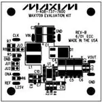
MAX1709 Evaluation Kit
The MAX1709 evaluation kit (EV kit) is a step-up DC-DC
switching regulator for 1- to 3-cell battery inputs as well
as 2.5V or 3.3V regulated supply inputs. The EV kit
accepts a positive input between 0.7V and VOUT and
converts it to a higher, pin-selectable output voltage.
Efficiency is up to 87% with output load currents to 4A.
This EV kit operates at a fixed 600kHz PWM frequency,
allowing the use of a small inductor.
A movable jumper on the EV kit selects either a 3.3V or
5V output voltage. Additional pads on the board
accommodate the resistors for output adjustment. This
EV kit uses surface-mount components and is fully
assembled and tested for quick evaluation.
Component List
DESIGNATION QTY
Features
♦ 0.7V to VOUT Input Voltage Range
♦ Pin-Selectable 3.3V or 5V Output Voltage
(5V as Shipped)
♦ Adjustable Output Voltage
(2.5V to 5.5V, External Divider)
♦ Up to 4A Output Current
♦ 600kHz PWM Operation
♦ Internal 10A MOSFET Switch
♦ 4µA IC Shutdown Current
♦ Surface-Mount Components
♦ Fully Assembled and Tested
DESCRIPTION
C1, C2
2
150µF, 6.3V low-ESR capacitors
Sanyo 6TPB150M or
Panasonic EEFUE0J151R
C4, C5
2
150µF, 6.3V, 15mΩ low-ESR capacitors
Panasonic EEFUE0J151R
C6
0
Not installed
C7
1
0.22µF ceramic capacitor (1206)
C8
1
1µF, 16V ceramic capacitor (1206)
Taiyo Yuden EMK316BJ105KL
TDK C3216X7R1C105M
C9, C10, C12
3
0.1µF ceramic capacitors (1206)
1
10A Schottky diode (DPAK)
Central Semiconductor CSHD10-45L
ON Semiconductor (Motorola)
MBRD1035CTL or
STM-Microelectronics STPS8L30B
SUPPLIER
PHONE
FAX
Central Semiconductor
516-435-1110
516-435-1824
D1
Ordering Information
PART
TEMP RANGE
MAX1709EVKIT
0°C to +70°C
IC PACKAGE
28-Pin TSSOP-EP*
*Exposed pad.
Component Suppliers
JU1, JU2, JU3
3
2-pin headers
Coilcraft
708-639-6400
708-639-1469
561-241-7876
561-241-9339
1
1µH, 10A power inductor
Coilcraft DO3316P-102HC or
Coiltronics UP2B-1R0
Coiltronics
L1
Dale- Vishay
402-564-3131
402-563-6418
R1, R2, R3
0
Not installed
ON Semiconductor
(Motorola)
602-303-5454
602-994-6430
R4
1
2Ω ±5% resistor (1206)
Panasonic
714-373-7939
714-373-7183
R5–R8
4
1MΩ ±5% resistors (1206)
Sanyo
619-661-6835
619-661-1055
U1
1
MAX1709EUI 28-pin TSSOP-EP
STM- Microelectronics
617-259-0300
617-259-9442
None
3
Shunts
Sumida
847-956-0666
847-956-0702
None
1
MAX1709 PC board
Taiyo Yuden
408-573-4150
408-573-4159
None
1
MAX1709EV kit data sheet
None
1
MAX1709 data sheet
Note: Please indicate that you are using the MAX1709 when
contacting these component suppliers.
________________________________________________________________ Maxim Integrated Products
For pricing, delivery, and ordering information, please contact Maxim/Dallas Direct! at
1-888-629-4642, or visit Maxim’s website at www.maxim-ic.com.
1
Evaluates: MAX1709
General Description
�Evaluates: MAX1709
MAX1709 Evaluation Kit
Quick Start Reference
Detailed Description
The MAX1709 EV kit is fully assembled and tested.
Follow these steps to verify board operation.
Do not turn on the power supply until all connections are completed:
1) Connect a voltmeter to the VOUT pad.
The MAX1709 EV kit provides a pin-selectable 3.3V or
5V output from a 0.7V to VOUT input voltage. The output
voltage can also be adjusted with external resistors for
voltages between 2.5V and 5.5V.
The MAX1709 includes an internal MOSFET switch with
a typical peak current limit of 10A and can deliver loads
up to 4A. Connecting an external resistor from SS/LIM
to GND (R3) can also reduce the current limit.
Connecting a capacitor from SS/LIM to GND (C10) sets
the soft-start rate.
The EV kit operates at a 600kHz switching frequency
and allows the use of a small inductor value. The
switching frequency can also be synchronized to an
external clock ranging from 350kHz to 1MHz.
2) Connect a 3V supply to the VIN pad. Connect
ground to the GND pad.
3) Remove all the shunts from JU1, JU2, and JU3. Turn
on the power supply and verify that the output voltage
is 5V. Refer to the MAX1709 data sheet for output
load during startup.
4) For other output voltages, refer to the Setting the
Output Voltage section in the MAX1709 data sheet
for instructions on selecting feedback resistors R1
and R2.
Jumper Selection
Three jumpers on the PC board allow user selection of
several configurations. Table 1 lists the jumpers and
their functions.
Table 1. Jumper Functions
JUMPER
JU1
JU2
JU3
2
SHUNT
LOCATION
Not installed
ONB connected to GND
MAX1709 is enabled if ONA = VOUT.
Installed
ONB connected to VOUT
MAX1709 is disabled if ONA = GND.
Not installed
ONA connected to GND
MAX1709 is disabled if ONB = VOUT.
Installed
ONA connected to VOUT
MAX1709 is enabled if ONB = GND.
Not installed
3.3/5 connected to VOUT
VOUT is set to 5V. FB pin must be connected to ground (R2 = short).
3.3/5 connected to GND
VOUT is set to 3.3V. FB pin must be connected to ground (R2 = short).
3.3/5 connected to GND
and resistors R1, R2 are
installed
VOUT = adjustable between 2.5V to 5.5V. Refer to the Setting the
Output Voltage section in the MAX1709 data sheet for instructions on
selecting feedback resistors R1 and R2. Also cut PC trace shorting R2.
Installed
PIN CONNECTION
MAX1709 OPERATION
_______________________________________________________________________________________
�REF
1.25V
CLK
ONA
ONB
GND
R7
1MΩ
R3
OPEN
VOUT
JU2
VOUT
C7
0.22µF
C10
0.1µF
JU1
VOUT
14
11
13
10
9
6
27
R6
1MΩ
1
R5
1MΩ
28
GND
GND
REF
NC
NC
SS/LIM
U1
MAX1709
CLK/SEL
ONA
ONB
3.3/5
NC
NC
FB
NC
OUT
PGND1
PGND1
PGND2
PGND2
PGND3
PGND3
LX1
LX1
LX1
LX2
LX2
LX3
LX3
26
25
24
16
17
15
18
19
20
21
22
23
2
3
4
5
6
7
8
1
C9
0.1µF
D1
JU3
2
R8
1MΩ
L1
1µH
VOUT
R4
2Ω
C4
150µF
6.3V
C1
150µF
6.3V
C5
150µF
6.3V
C2
150µF
6.3V
C6
OPEN
R2
SHORT
(PC TRACE)
R1
OPEN
C8
1µF
16V
C12
0.1µF
VOUT
5V AT 4A
GND
Evaluates: MAX1709
VIN
MAX1709 Evaluation Kit
Figure 1. MAX1709 EV Kit Schematic
_______________________________________________________________________________________
3
�Evaluates: MAX1709
MAX1709 Evaluation Kit
1.0"
1.0"
Figure 2. MAX1709 EV Kit Component Placement Guide—
Component Side
Figure 3. MAX1709 EV Kit PC Board Layout—Component Side
1.0"
Figure 4. MAX1709 EV Kit PC Board Layout—Solder Side
Maxim cannot assume responsibility for use of any circuitry other than circuitry entirely embodied in a Maxim product. No circuit patent licenses are
implied. Maxim reserves the right to change the circuitry and specifications without notice at any time.
4 _____________________Maxim Integrated Products, 120 San Gabriel Drive, Sunnyvale, CA 94086 408-737-7600
© 2005 Maxim Integrated Products, Inc.
Printed USA
is a registered trademark of Maxim Integrated Products.
�
很抱歉,暂时无法提供与“MAX1709EVKIT”相匹配的价格&库存,您可以联系我们找货
免费人工找货