19-1993; Rev 3; 9/02
KIT
ATION
EVALU
E
L
B
A
AVAIL
High-Speed Step-Down Controller with
Accurate Current Limit for Notebook Computers
Features
♦ Ultra-High Efficiency
Maxim’s proprietary Quick-PWM™ quick-response,
constant-on-time PWM control scheme handles wide
input/output voltage ratios with ease and provides
100ns “instant-on” response to load transients while
maintaining a relatively constant switching frequency.
Efficiency is enhanced by an ability to drive very large
synchronous-rectifier MOSFETs. Accurate current sensing to ensure reliable overload protection is available
using an external current-sense resistor in series with
the synchronous rectifier. Alternatively, the synchronous
rectifier itself can be used for less accurate current
sensing at the lowest possible power dissipation.
Single-stage buck conversion allows the MAX1844 to
directly step down high-voltage batteries for the highest
possible efficiency. Alternatively, two-stage conversion
(stepping down the 5V system supply instead of the
battery) at a higher switching frequency allows the minimum possible physical size.
The MAX1844 is intended for CPU core, chipset,
DRAM, or other low-voltage supplies as low as 1V. It is
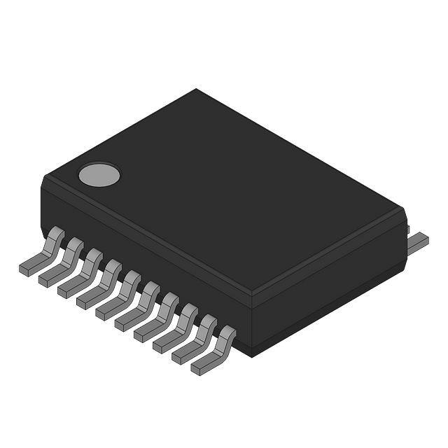
available in 20-pin QSOP, and QFN packages and
includes both adjustable overvoltage and undervoltage
protection.
♦ 1.8V/2.5V Fixed or 1V to 5.5V Adjustable Output
Range
For a dual step-down PWM controller with accurate current limit, refer to the MAX1845. The MAX1714/ MAX1715
single/dual PWM controllers are similar to the MAX1844/
MAX1845 but do not use current-sense resistors.
Applications
Notebook Computers
♦ Accurate Current-Limit Option
♦ Quick-PWM with 100ns Load-Step Response
♦ 1% VOUT Accuracy Over Line and Load
♦ 2V to 28V Battery Input Range
♦ 200/300/450/600kHz Switching Frequency
♦ Adjustable Overvoltage Protection
♦ Adjustable Undervoltage Protection
♦ 1.7ms Digital Soft-Start
♦ Drives Large Synchronous-Rectifier FETs
♦ 2V ±1% Reference Output
♦ Power-Good Window Comparator
Ordering Information
TEMP RANGE
PIN-PACKAGE
MAX1844EEP
PART
-40°C to +85°C
20 QSOP
MAX1844EGP*
-40°C to +85°C
20 QFN
MAX1844ETP
-40°C to +85°C
20 Thin QFN
Minimal Operating Circuit
BATTERY
4.5V TO 28V
5V INPUT
VCC
SHDN
UVP
BST
ILIM
CPU Core Supplies
Chipset/RAM Supplies as Low as 1V
VDD
V+
DH
MAX1844
LX
REF
1.8V and 2.5V Supplies
OUTPUT
2.5V
DL
PGOOD
CS
LATCH
*Contact factory for availability.
OUT
OVP
FB
SKIP
Quick-PWM is a trademark of Maxim Integrated Products.
Pin Configuration appears at end of data sheet.
GND
________________________________________________________________ Maxim Integrated Products
For pricing, delivery, and ordering information, please contact Maxim/Dallas Direct! at
1-888-629-4642, or visit Maxim’s website at www.maxim-ic.com.
1
MAX1844
General Description
The MAX1844 pulse-width modulation (PWM) controller
provides high efficiency, excellent transient response,
and high DC output accuracy needed for stepping
down high-voltage batteries to generate low-voltage
CPU core or chipset/RAM supplies in notebook computers.
�MAX1844
High-Speed Step-Down Controller with
Accurate Current Limit for Notebook Computers
ABSOLUTE MAXIMUM RATINGS
V+ to GND ..............................................................-0.3V to +28V
VCC, VDD to GND .....................................................-0.3V to +6V
OUT, PGOOD, SHDN to GND ..................................-0.3V to +6V
FB, ILIM, LATCH, OVP, REF, SKIP,
TON, UVP to GND ..................................-0.3V to (VCC + 0.3V)
BST to GND ............................................................-0.3V to +34V
CS to GND.................................................................-6V to +30V
DL to GND ..................................................-0.3V to (VDD + 0.3V)
DH to LX .....................................................-0.3V to (BST + 0.3V)
LX to BST..................................................................-6V to +0.3V
REF Short Circuit to GND ...........................................Continuous
Continuous Power Dissipation (TA = +70°C)
20-Pin QSOP (derate 9.1mW/°C above +70°C)...........727mW
20-Pin 5mm ✕ 5mm QFN (derate 20.0mW/°C
above +70°C).................................................................1.60W
Operating Temperature Range ...........................-40°C to +85°C
Junction Temperature ......................................................+150°C
Storage Temperature Range .............................-65°C to +150°C
Lead Temperature (soldering, 10s) .................................+300°C
Stresses beyond those listed under “Absolute Maximum Ratings” may cause permanent damage to the device. These are stress ratings only, and functional
operation of the device at these or any other conditions beyond those indicated in the operational sections of the specifications is not implied. Exposure to
absolute maximum rating conditions for extended periods may affect device reliability.
ELECTRICAL CHARACTERISTICS
(Circuit of Figure 1, V+ = 15V, VCC = VDD = 5V, SKIP = GND, TA = 0°C to +85°C, unless otherwise noted. Typical values are at
TA = +25°C.)
PARAMETER
Input Voltage Range
CONDITIONS
MIN
Battery voltage, V+
VCC , VDD
TYP
MAX
2
28
4.5
5.5
FB = OUT
0.99
FB = GND
2.475
2.5
2.525
FB = VCC
1.782
1.8
1.818
UNITS
V
1.01
Error Comparator Threshold
(DC Output Voltage Accuracy)
(Note 1)
V+ = 4.5V to 28V,
SKIP = VCC
Load Regulation Error
ILOAD = 0 to 3A, SKIP = VCC
9
mV
Line Regulation Error
VCC = 4.5V to 5.5V, V+ = 4.5V to 28V
5
mV
FB Input Bias Current
Output Adjustment Range
OUT Input Resistance
Soft-Start Ramp Time
On-Time
-0.1
+0.1
µA
1
5.5
V
FB = GND
90
190
350
FB = VCC or adjustable feedback mode
70
145
270
TON = GND (600kHz)
140
160
180
TON = REF (450kHz)
175
200
225
TON = unconnected (300kHz)
260
290
320
TON = VCC (200kHz)
380
425
470
Rising edge of SHDN to full current limit
V+ = 24V,
VOUT = 2V
(Note 2)
V
1.7
kΩ
ms
ns
Minimum Off-Time
(Note 2)
400
500
ns
Quiescent Supply Current (VCC)
FB forced above the regulation point
550
800
µA
Quiescent Supply Current (VDD)
FB forced above the regulation point
很抱歉,暂时无法提供与“MAX1844EEP”相匹配的价格&库存,您可以联系我们找货
免费人工找货