Click here for production status of specific part numbers.
MAX20004/MAX20006/
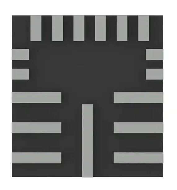
MAX20008
36V, 220kHz to 2.2MHz, 4A/6A/8A
Fully Integrated Automotive
Step-Down Converters
General Description
The MAX20004/MAX20006/MAX20008 are small, synchronous, automotive buck converter devices with integrated
high-side and low-side MOSFETs. The device family can
deliver up to 8A with input voltages from 3.5V to 36V, while
using only 25μA quiescent current at no load. Voltage quality can be monitored by observing the RESET signal. The
devices can operate in dropout by running at 98% duty
cycle, making them ideal for automotive applications.
The devices offer fixed output voltages of 5V and 3.3V,
along with the ability to program the output voltage between
1V and 10V. Frequency is resistor programmable from
220kHz to 2.2MHz. The devices offer a forced fixed-frequency PWM mode (FPWM) and skip mode with ultra-low
quiescent current. The devices can be factory programmed
to enable spread-spectrum switching to reduce EMI.
The MAX20004/MAX20006/MAX20008 are available in a
small, 3.5mm x 3.75mm, 17-pin FC2QFN package and use
very few external components.
Applications
● Point-of-Load (PoL) Applications in Automotive
● Distributed DC Power Systems
● Navigation and Radio Head Units
Benefits and Features
● Multiple Functions for Small Size
• Operating VIN Range of 3.5V to 36V
• 25µA Quiescent Current in Skip Mode
• Synchronous DC-DC Converter with
Integrated FETs
• 220kHz to 2.2MHz Adjustable Frequency
• Fixed 5ms Internal Soft-Start
• Programmable 1V to 10V Output, or 3.3V and
5.0V Fixed-Output Options Available
• 98% Duty-Cycle Operation with Low Dropout
• RESET Output
● High Precision
• ±2% Output-Voltage Accuracy
• Good Load-Transient Performance
● Robust for the Automotive Environment
• Current-Mode, Forced-PWM and Skip Operation
• Overtemperature and Short-Circuit Protection
• 3.5mm x 3.75mm 17-Pin FC2QFN
• -40°C to +125°C Operating Temperature Range
• 40V Load-Dump Tolerant
• AEC-Q100 Qualified
Ordering Information appears at end of data sheet.
Typical Application Circuit
CIN1
4.7µF
CIN2
0.1µF
SUPSW
FOSC
SUP
SYNC
EN
VOUT
COUT
19-100239; Rev 8; 11/19
L
1µH
0.1 µF
CBST
OUT
BST
LX
PGND
12 kΩ
RRESET
20 kΩ
BIAS
RESET
COMP
FB
BIAS
GND
22 kΩ
CBIAS
2.2 µF
1n F
4.7 pF
�MAX20004/MAX20006/
MAX20008
36V, 220kHz to 2.2MHz, 4A/6A/8A
Fully Integrated Automotive
Step-Down Converters
Absolute Maximum Ratings
SUP, EN, SUPSW to PGND...................................-0.3V to +40V
LX to PGND (Note 1)......................... -0.3V to (VSUPSW + 0.3V)
BIAS, RESET to GND...........................................-0.3V to +6.0V
FOSC, COMP to GND............................-0.3V to (VBIAS + 0.3V)
SYNC, FB to GND...................................-0.3V to (VBIAS + 0.3V)
GND to PGND.......................................................-0.3V to +0.3V
OUT to PGND........................................................-0.3V to +12V
BST to LX ................................................................-0.3V to +6V
LX Continuous RMS Current ..................................................8A
Output Short-Circuit Duration.....................................Continuous
Continuous Power Dissipation (TA = +70°C)
17-Pin FC2QFN (derate 29.4mW/°C > 70°C)........... 2553mW
Operating Temperature Range.......................... -40°C to +125°C
Junction Temperature.......................................................+150°C
Storage Temperature Range............................. -65°C to +150°C
Lead Temperature Range.................................................+300°C
Soldering Temperature (reflow)........................................+260°C
Stresses beyond those listed under “Absolute Maximum Ratings” may cause permanent damage to the device. These are stress ratings only, and functional operation of the device at these
or any other conditions beyond those indicated in the operational sections of the specifications is not implied. Exposure to absolute maximum rating conditions for extended periods may affect
device reliability.
Note 1: Self-protected from transient voltages exceeding these limits in circuit under normal operation.
Package Information
17 FC2QFN
Package Code
F173A3FY+1
Outline Number
21-100155
Land Pattern Number
90-100056
Thermal Resistance, Four-Layer Board:
Junction to Ambient (θJA)
27°C/W
Junction to Case (θJC)
2.6°C/W
For the latest package outline information and land patterns (footprints), go to www.maximintegrated.com/packages. Note that a “+”,
“#”, or “-” in the package code indicates RoHS status only. Package drawings may show a different suffix character, but the drawing
pertains to the package regardless of RoHS status.
Package thermal resistances were obtained using the EV kit. For detailed information on package thermal considerations, refer to
www.maximintegrated.com/thermal-tutorial.
Electrical Characteristics
(VSUP = VSUPSW = VEN = 14V. TA = TJ = -40°C to +125°C, unless otherwise noted. Typical values are at TA = +25°C under normal
conditions, unless otherwise noted.) (Note 2)
PARAMETER
SYMBOL
Supply Voltage Range
VSUP,
VSUPSW
Supply Voltage Range
VSUP,
VSUPSW
Supply Current
ISUP
CONDITIONS
MIN
TYP
3.5
After startup
Skip mode, no load
VOUT = 3.3V
25
32
30
42
10
5
BIAS Regulator Voltage
VBIAS
VSUP = VSUPSW = 6V to 40V IBIAS < 10mA,
BIAS not switched over to VOUT
5
www.maximintegrated.com
V
VOUT = 5.0V
VEN = 0V
VBIAS rising
36
V
ISHDN
VUVBIAS
UNITS
3.0
Shutdown Supply Current
BIAS Undervoltage
Lockout
MAX
2.7
3
µA
µA
V
3.3
V
Maxim Integrated │ 2
�MAX20004/MAX20006/
MAX20008
36V, 220kHz to 2.2MHz, 4A/6A/8A
Fully Integrated Automotive
Step-Down Converters
Electrical Characteristics (continued)
(VSUP = VSUPSW = VEN = 14V. TA = TJ = -40°C to +125°C, unless otherwise noted. Typical values are at TA = +25°C under normal
conditions, unless otherwise noted.) (Note 2)
PARAMETER
SYMBOL
BIAS Undervoltage
Lockout
VUVBIAS
Thermal-Shutdown
Temperature
TSHDN
Thermal-Shutdown
Hysteresis
THYST
CONDITIONS
MIN
TYP
MAX
UNITS
VBIAS falling
2.5
2.9
V
TJ rising
175
°C
15
°C
OUTPUT VOLTAGE
PWM-Mode Output
Voltage (Note 3)
VOUT_5V
VSUP = VSUPSW = 6V to 28V
4.9
5
5.1
V
Skip-Mode Output Voltage
(Note 4)
VSKIP_5V
Skip mode, no load, FB = BIAS
4.9
5
5.15
V
PWM-Mode Output
Voltage
VOUT_3.3V
VSUP = VSUPSW = 6V to 28V
3.23
3.3
3.37
V
Skip-Mode Output Voltage
(Note 4)
VSKIP_3.3V
Skip mode, no load, FB = BIAS
3.23
3.3
3.4
V
Load Regulation
LNREG
Line Regulation
LDREG
VFB = VBIAS, 30mA < ILOAD < 6A, PWM mode,
5V
VFB = VBIAS, 6V < VSUPSW < 36V, PWM mode
0.6
%
0.02
%/V
BST Input Current
IBST_ON
High-side MOSFET on, VBST - VLX = 5V
1.5
mA
BST Input Current
IBST_OFF
High-side MOSFET off, VBST - VLX = 5V
0.1
µA
LX Current Limit
LX Rise Time (Note 4)
ILX
SS
High-Side Switch
On-Resistance
RHS
Low-Side Switch
On-Resistance
Low-Side Switch Leakage
5.25
7
8.75
MAX20006 (6A)
7.5
10
12.5
MAX20008 (8A)
10.5
14
17.5
IHS_LKG
RLS
ILS_LKG
A
2
ns
Spread spectrum enabled
±3
%
VBIAS = 5V, ILX = 2A
38
76
mΩ
High-side MOSFET off, VSUPSW = 36V,
VLX = 0V, TA = +25°C
1
5
µA
VBIAS = 5V, ILX = 2A
18
36
mΩ
Low-side MOSFET off, VSUPSW = 36V,
VLX = 36V, TA = +25°C
1
5
µA
30
100
nA
tLX_TR
Spread Spectrum
High-Side Switch Leakage
MAX20004 (4A)
FB Input Current
IFB
TA = +25°C
FB Regulation Voltage
VFB
FB connected to an external resistive divider,
6V < VSUPSW < 36V
0.99
1.00
1.01
V
Transconductance
(from FB to COMP)
gm
VFB = 1V, VBIAS = 5V
500
780
1000
µS
Minimum On-Time
(Note 4)
tON_MIN
Load 500mA (Note 4)
www.maximintegrated.com
75
ns
Maxim Integrated │ 3
�MAX20004/MAX20006/
MAX20008
36V, 220kHz to 2.2MHz, 4A/6A/8A
Fully Integrated Automotive
Step-Down Converters
Electrical Characteristics (continued)
(VSUP = VSUPSW = VEN = 14V. TA = TJ = -40°C to +125°C, unless otherwise noted. Typical values are at TA = +25°C under normal
conditions, unless otherwise noted.) (Note 2)
PARAMETER
SYMBOL
CONDITIONS
MIN
TYP
MAX
UNITS
Maximum Duty Cycle
DCMAX
97
98
Oscillator Frequency
fSW1
RFOSC = 73.2kΩ
360
400
440
kHz
Oscillator Frequency
fSW2
RFOSC = 12kΩ
2.0
2.2
2.4
MHz
Soft-Start Time
tSS
%
5
ms
EN, SYNC
External Input Clock
Frequency
RFOSC = 12kΩ (Note 5)
SYNC High Threshold
VSYNC_HI
SYNC Low Threshold
VSYNC_LO
SYNC Leakage Current
ISYNC
EN High Threshold
VEN_HI
EN Low Threshold
VEN_LO
EN Hysteresis
EN Leakage Current
RESET
UV Threshold
1.8
1.4
TA = +25°C
0.1
UVACC
Falling
89
UV Hysteresis
Hold Time (Note 6)
UV Debounce Time
tHOLD1
(Note 6)
tDEB
OVPTHR
Rising
OV Protection Threshold
OVPTHF
Falling
Leakage Current
IRST_LKG
VOUT in regulation, TA = +25°C
Output Low Level
VROL
2:
3:
4:
5:
6:
V
1
µA
V
0.6
V
0.1
2
µA
91
93
%
V
3
%
0.2
ms
25
OV Protection Threshold
Note
Note
Note
Note
Note
0.4
0.2
TA = +25°C
104
MHz
V
2.4
VEN_HYS
IEN
2.6
107
µs
110
105
ISINK = 5mA
%
%
1
µA
0.4
V
All units are 100% production tested at TA = +25˚C. All temperature limits are guaranteed by design.
Device not in dropout condition.
Guaranteed by design. Not production tested.
Contact factory for SYNC frequency outside the specified range.
Contact factory for additional options.
www.maximintegrated.com
Maxim Integrated │ 4
�MAX20004/MAX20006/
MAX20008
36V, 220kHz to 2.2MHz, 4A/6A/8A
Fully Integrated Automotive
Step-Down Converters
Typical Operating Characteristics
(VSUP = VSUPSW = 14V, VEN = 14V, VOUT = 5V, VFSYNC = 0V, RFOSC = 12kΩ, TA = +25°C, unless otherwise noted.)
EFFICIENCY vs. LOAD CURRENT
100
100
90
90
80
80
70
70
SKIP MODE
60
EFFICIENCY (%)
EFFICIENCY (%)
EFFICIENCY vs. LOAD CURRENT
toc01
PWM MODE
50
40
30
20
10
0
0.001
0.01
0.1
SKIP MODE
60
PWM MODE
50
40
30
20
VIN = 12V
VOUT = 5V
fSW = 400kHz
VIN = 12V
VOUT = 3.3V
fSW = 400kHz
10
1
0
0.001
10
0.01
0.1
EFFICIENCY vs. LOAD CURRENT
100
90
80
EFFICIENCY (%)
EFFICIENCY (%)
70
SKIP MODE
60
PWM MODE
40
30
10
0.01
0.1
1
SKIP MODE
60
50
PWM MODE
40
30
20
VIN = 12V
VOUT = 5V
fSW = 2.2MHz
0
0.001
toc04
100
80
20
VIN = 12V
VOUT = 3.3V
fSW = 2.2MHz
10
0
0.001
10
0.01
LOAD CURRENT (A)
1
10
NO LOAD SUPPLY CURRENT
vs. SUPPLY VOLTAGE
toc05
10
35
VEN = 0V
SUPPLY CURRENT (uA)
7
6
5
4
3
toc06
VOUT = 3.3V
fSW = 2.2MHz
SKIP MODE
30
8
SUPPLY CURRENT (uA)
0.1
LOAD CURRENT (A)
SHUTDOWN CURRENT vs. SUPPLY VOLTAGE
9
10
EFFICIENCY vs. LOAD CURRENT
toc03
90
50
1
LOAD CURRENT (A)
LOAD CURRENT (A)
70
toc02
25
20
15
10
2
5
1
0
6
9
12
15
18
21
24
27
SUPPLY VOLTAGE (V)
www.maximintegrated.com
30
33
36
0
6
9
12
15
18
21
24
27
30
33
36
SUPPLY VOLTAGE (V)
Maxim Integrated │ 5
�MAX20004/MAX20006/
MAX20008
36V, 220kHz to 2.2MHz, 4A/6A/8A
Fully Integrated Automotive
Step-Down Converters
Typical Operating Characteristics
(VSUP = VSUPSW = 14V, VEN = 14V, VOUT = 5V, VFSYNC = 0V, RFOSC = 12kΩ, TA = +25°C, unless otherwise noted.)
SWITCHING FREQUENCY vs. RFOSC
SYNC FUNCTION
toc07
2500
toc08
SWITCHING FREQUENCY (kHz)
2250
2000
1750
VLX
5V/div
VSYNC
1V/div
1500
1250
1000
750
500
250
0
10
30
50
70
90
110
130
150
200ns/div
ROSC (kΩ)
VBIAS vs. VSUP
4.5
IOUT = 6A
4.0
3.5
3.0
0.40
0.35
VSET = 3.3V
0.30
0.25
0.20
VSET = 5V
0.15
0.10
2.5
2.0
VOUT = 95% of VSET
L = COILCRAFT XAL6030-102
0.45
DROPOUT VOLTAGE (V)
VBIAS (V)
5.0
0.05
0.00
2.0
2.5
3.0
3.5
4.0
4.5
5.0
5.5
6.0
0
1
2
3
LOAD REGULATION
6
toc12
5.20
VIN = 14V
PWM MODE
VIN = 14V
SKIP MODE
5.15
5.10
5.10
400kHz
5.05
VOUT (V)
VOUT (V)
5
LOAD REGULATION
toc11
5.20
5.15
4
IOUT (A)
VSUP (V)
5.00
400kHz
5.05
5.00
4.95
4.95
2.2MHz
4.90
2.2MHz
4.90
4.85
4.85
4.80
toc10
0.50
IOUT = 0.1A
VOUT = 3.3V
fSW = 2.2MHz
5.5
DROPOUT VOLTAGE vs. IOUT
toc09
6.0
4.80
0
1
2
3
4
IOUT (A)
www.maximintegrated.com
5
6
7
8
0
1
2
3
4
IOUT (A)
5
6
7
8
Maxim Integrated │ 6
�MAX20004/MAX20006/
MAX20008
36V, 220kHz to 2.2MHz, 4A/6A/8A
Fully Integrated Automotive
Step-Down Converters
Typical Operating Characteristics
(VSUP = VSUPSW = 14V, VEN = 14V, VOUT = 5V, VFSYNC = 0V, RFOSC = 12kΩ, TA = +25°C, unless otherwise noted.)
ENABLE STARTUP BEHAVIOR
VOUT vs. VIN
toc14
toc13
5.05
VIN = 14V
PWM MODE
ILOAD = 0A
5.04
5V/div
VEN
400kHz
VOUT (V)
5.03
2V/div
VOUT
5.02
5.01
5.00
4.99
2A/div
IOUT
2.2MHz
5V/div
VRESET
6
12
18
24
30
4ms/div
36
VIN (V)
SHORT CIRCUIT AND RECOVERY
VIN STARTUP BEHAVIOR
toc16
toc15
10V/div
VIN
2V/div
VOUT
2V/div
10V/div
VLX
VOUT
2A/div
IOUT
IOUT
VRESET
20A/div
5V/div
EN = VIN
4ms/div
20ms/div
TJ_RISE vs. IOUT
toc17
80
fSW = 2.2MHz
VIN = 14V
PWM MODE
TA = 25°C
60
VOUT = 5V
50
VOUT = 3.3V
40
30
20
VOUT = 5V
toc18
fSW = 400kHz
VIN = 14V
PWM MODE
TA = 25°C
70
TJ_RISE (°C)
TJ_RISE (°C)
TJ_RISE vs. IOUT
140
130
120
110
100
90
80
70
60
50
40
30
20
10
0
VOUT = 3.3V
10
1
2
3
4
5
IOUT (A)
www.maximintegrated.com
6
7
8
0
1
2
3
4
5
6
7
8
IOUT (A)
Maxim Integrated │ 7
�MAX20004/MAX20006/
MAX20008
36V, 220kHz to 2.2MHz, 4A/6A/8A
Fully Integrated Automotive
Step-Down Converters
Pin Configuration
FOSC
FB
COMP
GND
BIAS
SYNC
TOP VIEW
17
16
15
14
13
12
OUT
1
11
EN
RESET
2
10
SUP
BST
3
9
SUPSW
PGND
4
8
PGND
PGND
5
7
PGND
LX
6
FC2QFN
3.5mm x 3.75mm
Pin Description
PIN
NAME
FUNCTION
1
OUT
2
RESET
3
BST
4, 5,
7, 8
PGND
6
LX
9
SUPSW
10
SUP
11
EN
12
SYNC
Connect SYNC to GND or leave unconnected to enable skip-mode operation under light loads. Connect SYNC
to BIAS or to an external clock to enable fixed-frequency forced-PWM-mode operation. When driving SYNC
externally, do not exceed the BIAS or OUT voltage.
13
BIAS
Linear Regulator Output. BIAS supplies the internal circuitry. Bypass with a minimum 2.2 µF ceramic capacitor
to ground. The BIAS pin can transition from 5V to VOUT after startup.
14
GND
Analog Ground
Switching Regulator Output. OUT also provides power to the internal circuitry under certain conditions (see the
Linear Regulator Output (BIAS) section for details).
Open-Drain, Active-Low RESET Output. To obtain a logic signal, pullup RESET with an external resistor.
High-Side Driver Supply. Connect a 0.1μF capacitor between LX and BST for proper operation.
Power Ground. Connect all PGND pins together.
Inductor Connection. Connect LX to the switched side of the inductor.
Internal High-Side Switch Supply Input. SUPSW provides power to the internal switch. Bypass SUPSW to
PGND with 0.1μF and 4.7μF ceramic capacitors. Place the 0.1μF capacitor as close as possible to the SUPSW
and PGND pins, followed by the 4.7μF capacitor.
Voltage Supply Input. SUP supplies the internal linear regulator. Connect SUP directly to SUPSW as close as
possible to the IC. SUP and SUPSW are connected together internally.
SUP Voltage-Compatible Enable Input. Drive EN low to disable the device. Drive EN high to enable the device.
For a safe startup, ensure that VSUP > 7.5V when EN is toggled high.
www.maximintegrated.com
Maxim Integrated │ 8
�MAX20004/MAX20006/
MAX20008
36V, 220kHz to 2.2MHz, 4A/6A/8A
Fully Integrated Automotive
Step-Down Converters
Pin Description (continued)
PIN
NAME
15
COMP
16
FB
17
FOSC
FUNCTION
Error-Amplifier Output. Connect an RC network from COMP to GND for stable operation. See the
Compensation Network section for more details.
Feedback Input. Connect an external resistive divider from OUT to FB and GND to set the output voltage.
Connect FB to BIAS to set the output voltage to 5V or 3.3V.
Resistor-Programmable Switching Frequency Setting Control Input. Connect a resistor from FOSC to GND to
set the switching frequency.
Internal Block Diagram
CURRENT-SENSE
AMP
MAX20004
MAX20006
MAX20008
SUPSW
SKIP CURRENT
COMP
BST
CLK
PEAK CURRENT
COMP
RAMP
GENERATOR
CONTROL LOGIC
∑
LX
LX
BIAS
PWM
COMP
PGND
COMP
VREF
ERROR
AMP
SOFT-START
GENERATOR
OUT
FB
PGOOD
COMP
OSC
ZX
COMP
PGND
POK
FEEDBACK
SELECT
SYNC
FOSC
FPWM CLK
CLK
FPWM
POK
OTP
VOLTAGE
REFERENCE
SUP
TRIMBITS
BIAS LDO
VREF
BIAS
RESET
EN
MAIN
CONTROL
LOGIC
GND
SEL
GND
www.maximintegrated.com
Maxim Integrated │ 9
�MAX20004/MAX20006/
MAX20008
Detailed Description
The MAX20004/MAX20006/MAX2008 are 4A, 6A, and
8A current-mode step-down converters, respectively,
with integrated high-side and low-side MOSFETs. The
low-side MOSFET enables fixed-frequency FPWM operation in light-load applications. The devices operate with
3.5V to 36V input voltages, while using only 25μA (typ)
quiescent current at no load. The switching frequency
is resistor programmable from 220kHz to 2.2MHz and
can be synchronized to an external clock. The devices’
output voltage is available as fixed 5V or 3.3V, or adjustable between 1V and 10V. The wide input voltage range,
along with the ability to operate at 99% duty cycle during
undervoltage transients, make these devices ideal for
automotive applications.
In light-load applications, a logic input (SYNC) allows
the devices to operate either in skip mode for reduced
current consumption, or fixed-frequency FPWM mode
to eliminate frequency variation and help minimize EMI.
Protection features include cycle-by-cycle current limit,
and thermal shutdown with automatic recovery.
Thermal Considerations
The devices are available in 4A, 6A, or 8A versions; however, the average output-current capability is dependent on
several factors. Some of the key factors include the maximum ambient temperature (TA(MAX)), switching frequency
(fSW), and the number of layers and the size of the PCB.
See the Typical Operating Characteristics for a guideline.
Wide Input Voltage Range
The devices include two separate supply inputs (SUP and
SUPSW) specified for a wide 3.5V to 36V input voltage
range. VSUP provides power to the device and VSUPSW
provides power to the internal switch. When the device is
operating with a 3.5V input supply, conditions such as cold
crank can cause the voltage at the SUP and SUPSW pins
to drop below the programmed output voltage. Under such
conditions, the devices operate in a high duty-cycle mode
to facilitate minimum dropout from input to output.
Maximum Duty-Cycle Operation
The devices have an effective maximum duty cycle of 98%
(typ). The IC continuously monitors the time between lowside FET switching cycles in both PWM and skip modes.
Whenever the low-side FET has not switched for more than
13.5µs (typ), the low-side FET is forced on for 150ns (typ)
to refresh the BST capacitor. The input voltage at which
the device enters dropout changes depending on the input
voltage, output voltage, switching frequency, load current,
and the efficiency of the design.
www.maximintegrated.com
36V, 220kHz to 2.2MHz, 4A/6A/8A
Fully Integrated Automotive
Step-Down Converters
The input voltage at which the device enters dropout can
be approximated as:
VSUP =
VOUT
+ I OUT × R HS
0.98
where RHS is the high-side switch on-resistance, which
should also include the inductor DC resistance for better
accuracy.
Linear Regulator Output (BIAS)
The devices include a 5V linear regulator (VBIAS) that
provides power to the internal circuit blocks. Connect
a 2.2μF ceramic capacitor from BIAS to GND. Under
certain conditions, the BIAS regulator turns off and the
BIAS pin switches to OUT (i.e., switches over) after
startup to increase efficiency. For IC versions that are
factory trimmed for 3.3V fixed output, BIAS switches to
OUT under light load conditions in skip mode only. For IC
versions that are factory trimmed for 5V fixed output, the
BIAS pin switches to OUT after startup regardless of load
or skip/PWM mode. In any case, BIAS only switches over
if OUT is between 2.8V and 5.6V. In summary, BIAS can
transition from 5V to VOUT after startup depending on
load, mode and IC version.
Soft-Start
The devices include a fixed, internal soft-start. Soft-start
limits startup inrush current by forcing the output voltage
to ramp up towards its regulation point.
Reset Output (RESET)
The devices feature an open-drain reset output (RESET).
RESET asserts when VOUT drops below the specified
falling threshold. RESET deasserts when VOUT rises
above the specified rising threshold after the specified
hold time. Connect RESET to the output or I/O voltage
of choice (within pin voltage limits) with a pullup resistor.
Synchronization Input (SYNC)
SYNC is a logic-level input used for operating-mode
selection and frequency control. Connecting SYNC to
BIAS or to an external clock enables forced fixed-frequency (FPWM) operation. Connecting SYNC to GND enables
automatic skip-mode operation for light load efficiency.
The external clock frequency at SYNC can be higher or
lower than the internal clock by 20%. If the external clock
frequency is greater than 120% of the internal clock, contact the factory to verify the design. The devices synchronize to the external clock in two cycles. When the external
clock signal at SYNC is absent for more than two clock
cycles, the devices use the internal clock. There is a diode
Maxim Integrated │ 10
�MAX20004/MAX20006/
MAX20008
between SYNC and BIAS, so it is important when driving
SYNC with an external source that the voltage be less
than or equal to BIAS (or OUT in the case of switchover).
If this cannot be guaranteed, place a series resistor in-line
with SYNC ≥ 20kΩ to limit the input current. If EN is low,
BIAS is turned off so a voltage should not be present on
SYNC without the series resistor.
System Enable (EN)
An enable control input (EN) activates the devices from
their low-power shutdown mode. EN is compatible with
inputs from automotive battery level down to 3.5V.
EN turns on the internal linear (BIAS) regulator. Once
VBIAS is above the internal lockout threshold (VUVBIAS =
3V (typ)), the converter activates and the output voltage
ramps up with the programmed soft-start time.
A logic-low at EN shuts down the device. During shutdown, the BIAS regulator and gate drivers turn off.
Shutdown is the lowest power state and reduces the
quiescent current to 5μA (typ). Drive EN high to bring the
device out of shutdown.
For safe startup, ensure that VSUP > 7.5V when EN is
toggled high. In all applications, BIAS capacitance guidelines must be followed to ensure safe operation of the IC.
Note: In all applications, BIAS must start from < 0.3V or
> 1.6V during startup.
Spread-Spectrum Option
The devices can be ordered with spread spectrum
enabled. See the Ordering Information/Selector Guide
section. When the spread spectrum is factory enabled,
the operating frequency is varied ±3% centered on FOSC.
The modulation signal is a triangular wave with a frequency of 4.5kHz at 2.2MHz.
For operations at FOSC values other than 2.2MHz, the
modulation signal scales proportionally (e.g., at 400kHz,
the modulation frequency reduces by 0.4MHz/2.2MHz).
The internal spread spectrum is disabled if the devices
are synchronized to an external clock. However, the
devices do not filter the input clock on the SYNC pin and
pass any modulation (including spread spectrum) present
driving the external clock.
Internal Oscillator (FOSC)
The switching frequency (fSW) is set by a resistor
(RFOSC) connected from FOSC to GND. To determine
the approximate value of RFOSC for a given fSW, use the
www.maximintegrated.com
36V, 220kHz to 2.2MHz, 4A/6A/8A
Fully Integrated Automotive
Step-Down Converters
graph in the Typical Operating Characteristics section or
the following equation:
R=
FOSC
29,600
− 1.48
f SW
where fSW is in kHz and RFOSC is in kΩ. For example, a
400kHz switching frequency is set with RFOSC = 72.5kΩ.
Higher frequencies allow designs with lower inductor
values and less output capacitance at the expense of
reduced efficiency and higher EMI.
Thermal-Shutdown Protection
Thermal shutdown protects the device from excessive
operating temperature. When the junction temperature
exceeds the specified threshold, an internal sensor shuts
down the internal bias regulator and the step-down converter, allowing the IC to cool. The sensor turns the IC on
again after the junction temperature cools by the specified
hysteresis.
Current Limit/Short-Circuit Protection
The devices feature a current limit that protects them
against short-circuit and overload conditions at the output. In the event of a short-circuit or overload condition,
the high-side MOSFET remains on until the inductor
current reaches the specified LX current-limit threshold.
The converter then turns the high-side MOSFET off and
the low-side MOSFET on to allow the inductor current to
ramp down. Once the inductor current crosses below the
current-limit threshold, the converter turns on the highside MOSFET again. This cycle repeats until the short or
overload condition is removed.
A hard short is detected when the output voltage falls
below 50% of the target while in current limit. If this
occurs, hiccup mode activates, and the output turns off
for four times the soft-start time. The output then enters
soft-start and powers back up. This repeats indefinitely
while the short circuit is present. Hiccup mode is disabled
during soft-start.
Overvoltage Protection
If the output voltage exceeds the OV protection rising
threshold, the high-side MOSFET turns off and the lowside MOSFET turns on. Normal operation resumes when
the output voltage goes below the falling OV threshold.
Maxim Integrated │ 11
�MAX20004/MAX20006/
MAX20008
36V, 220kHz to 2.2MHz, 4A/6A/8A
Fully Integrated Automotive
Step-Down Converters
Applications Information
Forced-PWM and Skip Modes
Maximum Output Current
While there are device versions that supply up to 8A,
there are many factors that may limit the average output
current to less than the maximum. The devices can be
thermally limited based on the selected fSW, number of
PCB layers, PCB size, and the maximum ambient temperature. See the Typical Operating Characteristics section for guidance on the maximum average current. For a
more precise value, the θJA needs to be measured in the
application environment.
Setting the Output Voltage
Connect FB to BIAS for a fixed 5V or 3.3V output voltage. To set the output to other voltages between 1V and
10V, connect a resistive divider from output (OUT) to FB
(Figure 1). Select RFB2 (FB to GND resistor) less than or
equal to 100kΩ. Calculate RFB1 (OUT to FB resistor) with
the following equation:
V
=
R FB1 R FB2 OUT − 1
V
FB
where VFB is the feedback regulation voltage. See the
Electrical Characteristics table.
Add a capacitor, CFB1, as shown to compensate the pole
formed by the divider resistance and FB pin capacitance
as follows:
R FB2
C=
FB1 10pf ×
R FB1
Note: Applications that use a resistor divider to set
output voltages below 4.5V should use IC versions
that are factory trimmed for 3.3V fixed output voltage
to ensure full output current capability.
In forced-PWM (FPWM) mode, the devices switch at a
constant frequency with variable on-time. In skip mode,
the converter’s switching frequency is load-dependent.
At higher load current, the switching frequency becomes
fixed and operation is similar to PWM mode. Skip mode
helps improve efficiency in light-load applications by
allowing switching only when the output voltage falls
below a set threshold. Since the effective switching
frequency is lower in skip mode at light load, gate charge
and switching losses are lower and efficiency is increased.
Inductor Selection
Three key parameters must be considered when selecting an inductor: inductance value (L), inductor saturation
current (ISAT), and DC resistance (RDCR). The devises
are designed to operate with the ratio of inductor peakto-peak AC current to DC average current (LIR) between
15% and 30% (typ). The switching frequency, input voltage, and output voltage then determine the inductor value
as follows:
LMIN1 =
(VSUP − VOUT ) × VOUT
VSUP × f SW × IMAX × 30%
where VSUP and VOUT are typical values (so that efficiency is optimum for typical conditions) and IMAX is 4A
for MAX20004, 6A for MAX20006, and 8A for MAX20008,
and fSW is the switching frequency set by RFOSC. Note
that IMAX is the maximum rated output current for the
device, not the maximum load current in the application.
The next equation ensures that the internal compensating
slope is greater than 50% of the inductor current down slope:
m≥
m2
2
where m is the internal compensating slope and m2 is the
sensed inductor current down-slope as follows:
VOUT
RFB1
FB
RFB2
Figure 1. Adjustable Output-Voltage Setting
www.maximintegrated.com
=
m2
CFB1
VOUT
× R CS
L
where RCS is 0.38 for MAX20004, 0.28 for MAX20006,
and 0.21 for MAX20008.
=
m 1.35
V
f
× SW
µs 2.2MHz
Solving for L and using a 1.3 multiplier to account for
tolerances in the system:
R
L MIN2 = VOUT × CS × 1.3
2×m
Maxim Integrated │ 12
�MAX20004/MAX20006/
MAX20008
36V, 220kHz to 2.2MHz, 4A/6A/8A
Fully Integrated Automotive
Step-Down Converters
To satisfy both LMIN1 and LMIN2, LMIN must be set to the
larger of the two as follows:
L MIN = max ( L MIN1, L MIN2 )
The maximum nominal inductor value recommended is 2
times the chosen value from the above formula:
L MAX=
2 × L MIN
Select a nominal inductor value based on the following
formula:
input capacitance and ESR required for a specified input
voltage ripple using the following equations:
∆VESR
ESR IN =
∆I
I OUT + L
2
where:
(V − VOUT ) × VOUT
∆IL = SUP
VSUP × f SW × L
and:
C IN =
L MIN < L NOM < L MAX
The best choice of inductor is usually the standard inductor value closest to LNOM.
D=
Input Capacitor
The input filter capacitor reduces peak currents drawn
from the power source and reduces noise and voltage
ripple on the input due to high speed switching.
Place a 0.1μF capacitor as close as possible to the
SUPSW and PGND pins, followed by a 4.7μF (or larger)
ceramic capacitor. A bulk capacitor with higher ESR
(such as an electrolytic capacitor) is normally required as
well to lower the Q of the front-end circuit and provide the
remaining capacitance needed to minimize input voltage
ripple.
The input capacitor RMS current requirement (IRMS) is
defined by the following equation:
=
IRMS ILOAD(MAX) ×
VOUT × (VSUP − VOUT )
VSUP
IRMS has a maximum value when the input voltage
equals twice the output voltage:
VSUP= 2 × VOUT
therefore:
IRMS =
ILOAD(MAX)
2
Choose an input capacitor that exhibits less than +10°C
self-heating temperature rise at the RMS input current for
optimal long-term reliability.
The input-voltage ripple is composed of ∆VQ (caused by
the capacitor discharge) and ∆VESR (caused by the ESR
of the capacitor). Use low-ESR ceramic capacitors with
high ripple-current capability at the input. Calculate the
www.maximintegrated.com
I OUT × D(1 − D)
∆VQ × f SW
VOUT
VSUPSW
where:
IOUT is the maximum output current and D is the duty
cycle.
Output Capacitor
The output filter capacitor must have enough capacitance
and sufficiently low ESR to meet output-ripple requirements. In addition, the output capacitance must be high
enough to maintain the output voltage within specification
while the control loop responds to load changes.
When using high-capacitance, low-ESR capacitors, the
filter capacitor’s ESR dominates the output-voltage ripple,
so the size of the output capacitor depends largely on the
maximum ESR allowed to meet the output-voltage ripple
specifications as follows:
VRIPPLE(P−=
P) ESR × ∆IL
When using low-ESR (e.g. ceramic) output capacitors,
size is usually determined by the capacitance required
to maintain the output voltage within specification during
load transients and can be estimated as follows:
C OUT =
∆I
∆V × 2π × f C
where ∆I is the load change, ∆V is the allowed voltage
droop, and fC is the loop crossover frequency, which can
be assumed to be the lesser of fSW/10 or 100kHz. Any
calculations involving COUT should consider capacitance
tolerance, temperature, and voltage derating.
Maxim Integrated │ 13
�MAX20004/MAX20006/
MAX20008
36V, 220kHz to 2.2MHz, 4A/6A/8A
Fully Integrated Automotive
Step-Down Converters
VREF +
VERR
C(s)
VCOMP
M(s)
VOUT
-
VFB
F(s)
Figure 2. Control System
Compensation Network
The devices use a transconductance amplifier for external
frequency compensation. The compensation network in
conjunction with the output capacitance primarily determine the loop stability and response. The inductor and the
output capacitor are chosen based on performance, size,
and cost. The compensation network is used to optimize
the loop stability and response.
The converter uses a peak current mode control scheme
that regulates the output voltage by forcing the required
peak current through the external inductor. The devices
use the voltage drop across the high-side MOSFET to
sense inductor current. Current-mode control eliminates
the double pole in the feedback loop caused by the inductor and output capacitor, resulting in a smaller phase shift
and requiring less elaborate error-amplifier compensation
than voltage-mode control.
The final control system can be modeled according to
Figure 2 from which the following transfer function is
derived:
VOUT (s)
C(s)M(s)
=
VREF
1 + F(s)C(s)M(s)
where M(s), C(s) and F(s) are the modulator, compensator
and feedback transfer functions, respectively, VOUT is the
regulated output voltage and VREF is the internal voltage
reference. The product of the modulator, compensator and
feedback transfer functions is typically referred to as the
loop transfer function.
www.maximintegrated.com
A simplified condition for stability is that the denominator
of the transfer function never equals zero. Accordingly,
the loop transfer function should never equal -1, which
correspondingly means that the phase must not equal
-180 degrees when the magnitude equals 1. In addition,
the loop gain should be much less than zero when the
phase equals -180 degrees. The frequency at which the
magnitude of the loop gain equals 1 (or 0dB) is defined as
the crossover frequency (fc). The difference between the
loop phase at the crossover frequency and -180 degrees
is defined as the phase margin. The phase margin represents the additional loop phase lag that must occur at
the crossover frequency for the system to be unstable.
In addition to stability, phase margin is also related to
the transient response of the system. Insufficient phase
margin causes overshoot and ringing, whereas excessive
phase margin causes slow response.
The goal of the system is to have a high crossover frequency, so there is adequate gain to regulate against load
transients and other variations in the relevant frequency
range, while maintaining adequate phase margin to guard
against instability, overshoot, and ringing. In practice,
these are fundamentally conflicting criteria that must be
managed along with other design goals. According to
sampling theory, the crossover frequency cannot exceed
one half the switching frequency. In practice, noise and
phase margin considerations limit crossover frequency to
below one tenth the switching frequency with a practical
limit of approximately 100kHz.
Maxim Integrated │ 14
�MAX20004/MAX20006/
MAX20008
The modulator control (COMP) to output transfer function
of a current-mode buck regulator can be approximated
as follows:
s
1 + ωz_esr
VOUT (s)
R OUT
=
×
VCOMP (s) R CS
s
s
s2
+
+
+
1
1
ωp_load ωnQ
ωn 2
36V, 220kHz to 2.2MHz, 4A/6A/8A
Fully Integrated Automotive
Step-Down Converters
VOUT
gm
VREF
The first term is the DC gain, which is the quotient of the
equivalent load resistance (ROUT) and the current-sense
gain (RCS). The numerator is the zero due to the output
capacitance (COUT) and its equivalent series resistance
(RESR), which occurs at the following frequency:
1
fz_esr =
2π × R ESR × C OUT
The first term in the denominator is the pole due to the
load resistance and output capacitance, and occurs at the
following frequency:
1
fpload =
2π × R OUT × C OUT
The last term in the denominator is the sampling double
pole, which occurs at 1/2 of the switching frequency
(fSW/2). The sampling double pole typically occurs at
high frequency relative to the crossover frequency and
can generally be ignored if there is adequate slope compensation (i.e., low Q). In the typical application, where
the ESR is very low due to ceramic output capacitors,
the ESR zero also occurs at high frequency and can be
ignored as well. In these cases, the transfer function
simplifies to the low-frequency dominate pole model as
follows:
VOUT (s)
R OUT
1
=
×
s
VCOMP (s) R CS
1 + ωp_load
The type 2 compensation network (Figure 3) introduces
a zero, a low-frequency pole, and a high frequency pole
according to the simplified transfer function below:
s
1 + ωz_comp
= G EA × R EA ×
s
s
VERR (s)
1 + ωp1_comp 1 + ωp2_comp
VCOMP (s)
www.maximintegrated.com
COMP
RC
CF
CC
Figure 3. Compensation Network
where GEA and REA (1.5MΩ typ) are the transconductance
and output resistance of the error amplifier, respectively, and
the frequency of the poles and zeros are approximately as
follows:
1
fz_comp =
2π × R C × C C
fp1_comp =
1
2π × R EA × C C
fp2_comp =
1
2π × R C × C F
Compensation resistor, RC, primarily determines the compensator gain and, thus, crossover frequency, while the
separation of the compensator zero and high-frequency
pole determine the phase margin. The high-frequency
compensator pole is used to cancel the ESR zero or, in
the case of very high ESR zero frequency, limit the bandwidth for noise immunity. The low frequency compensator
pole is then placed to achieve adequate phase margin
and response, typically at the load pole frequency. The
selection of CC, therefore, becomes a tradeoff between
phase margin and response.The complete loop transfer
Maxim Integrated │ 15
�MAX20004/MAX20006/
MAX20008
36V, 220kHz to 2.2MHz, 4A/6A/8A
Fully Integrated Automotive
Step-Down Converters
function is the product of the product of the modulator,
compensator, and feedback transfer functions as follows:
F(s)C(s)M(s) =
VREF R OUT
×
× G EA × R EA
VOUT R CS
s
s
1 + ωz_esr 1 + ωz_comp
×
s
s
s
1 + ωp_load 1 + ωp1_comp 1 + ωp2_comp
The goal of compensation design is to reduce the loop
transfer function to an approximate single-pole system
with -20dB/decade gain slope and 90 degrees phase
margin at the crossover frequency. To achieve this, the
compensator zero is used to cancel the load pole, and
the compensator high frequency pole is used to cancel
the ESR zero. Assuming these cancellations, the loop
transfer function reduces to the following:
F(s)C(s)M(s)
=
× G EA × R EA ×
VREF R OUT
×
VOUT R CS
1
s
1 + ωp1_comp
To derive the compensation components, the magnitude
of the loop gain at the crossover frequency is set equal to
1 and solved for CC as follows (assuming the magnitude of
the compensator pole at the crossover frequency is >>1):
VREF R OUT
×
× G EA × R EA
VOUT R CS
Setting the compensator zero frequency equal to the load
pole frequency and solving for RC yields:
1
1
=
2π × R C × C C 2π × R OUT × C OUT
RC =
2π × C OUT × R CS × VOUT × f C
VREF × G EA
The above leads to an alternative equation for CC as
follows:
× C OUT
R
C C = OUT
RC
Finally, setting the high-frequency compensator pole
equal to the minimum of the ESR zero frequency or 1/2
the switching frequency and solving for CF yields:
f
1
1
= Min SW ,
2π × R C × C F
2
2
R
C
π
×
×
ESR
OUT
CF =
1
f
1
2π × R C × Min SW ,
π
×
×
2
2
R
C
ESR
OUT
The above equation leads to the following compensation
design procedure:
1) Select a crossover frequency equal to one tenth of
the switching frequency (fSW/10) or 100kHz, whichever is lower.
2) Calculate and select the compensation resistor, RC.
3) Calculate and select the compensation capacitor, CC.
1
4) Calculate and select compensation capacitor CF.
1
×
=
(2π × f C × R EA × C C )
5) Evaluate the gain and phase of the final loop transfer
function at the crossover frequency and adjust crossover frequency and/or compensation as required.
× R OUT × G EA
V
C C = REF
6) Verify the final design with transient line/load response
2π × f C × VOUT × R CS
testing and gain-phase measurements and adjust as
required.
www.maximintegrated.com
Maxim Integrated │ 16
�MAX20004/MAX20006/
MAX20008
PCB Layout Guidelines
Careful PCB layout is critical for stability, low-noise/
EMI and overall performance. Use a multilayer board
whenever possible for better noise immunity and power
dissipation. See Figure 4 for the following guidelines for
good PCB layout:
1) Use the correct footprint for the IC and place as
many copper planes as possible under the IC footprint to ensure efficient heat transfer.
2) Place the ceramic input bypass capacitors (CBP and
CIN) as close as possible to the SUPSW and PGND
pins on the same side as the IC. Use low-impedance
connections (no vias or other discontinuities) between the capacitors and IC pins. CBP should be
located closest to the IC and should have very good
high-frequency performance (small package size,
low inductance, and high. Use flexible terminations
or other technologies instead of series capacitors
for these functions if failure modes are a concern.
This approach provides the best EMI rejection and
minimizes internal noise on the device, which can
degrade performance.
3) Place the inductor (L), output capacitors (COUT),
boost capacitor (CBST) and BIAS capacitor (CB) on
the same side as the IC in such a way as to minimize
the area enclosed by the current loops. Place the
inductor (L) as close as possible to the IC LX pin and
minimize the area of the LX node. Place the output
capacitors (COUT) near the inductor and the ground
side of COUT near the CIN ground connection so as
to minimize the current the loop area. Place the BIAS
capacitor (CB) next to the BIAS pin.
www.maximintegrated.com
36V, 220kHz to 2.2MHz, 4A/6A/8A
Fully Integrated Automotive
Step-Down Converters
4) Use a contiguous copper GND plane on the layer
next to the IC to provide an image plane and shield
the entire circuit. GND should also be poured around
the entire circuit on the top side. Use a single GND:
do not separate or isolate PGND and GND connections with separate planes or copper areas. Ensure
that all heat-dissipating components have adequate
connections to copper for cooling. Use multiple vias
to interconnect GND planes/areas for low impedance
and maximum heat dissipation. Place vias at the GND
terminals of the IC, input/output/bypass capacitors,
and other components.
5) Place the compensation network (CF, CC, RC) near
the COMP pin so that the ground connections are as
short as possible to the GND pin. Keep high frequency
signals away from these components.
6) Place the oscillator set resistor (RF) near the FSET
pin so that the ground connection is as short as
possible to the GND pin. Keep high-frequency signals
away from this component.
7) Place the feedback resistor-divider (if used) near
the IC and route the feedback and OUT connections
away from the inductor and LX node and other noisy
signals.
Maxim Integrated │ 17
�MAX20004/MAX20006/
MAX20008
36V, 220kHz to 2.2MHz, 4A/6A/8A
Fully Integrated Automotive
Step-Down Converters
CC
RC
CF
CB
RF
1
VIN
CBST
CBP
CIN
LX
L
COUT
COUT
VOUT
Figure 4. Simplified Layout Example
www.maximintegrated.com
Maxim Integrated │ 18
�MAX20004/MAX20006/
MAX20008
36V, 220kHz to 2.2MHz, 4A/6A/8A
Fully Integrated Automotive
Step-Down Converters
Ordering Information/Selector Guide
PART
VOUT
(FB TIED TO BIAS)
VOUT
(EXTERNAL RESISTORDIVIDER) (V)
MAXIMUM
OPERATING
CURRENT (A)
THOLD
(ms)
SPREAD
SPECTRUM
MAX20004AFOA/VY+
5.0
MAX20004AFOB/VY+
3.3
4.5–10
4
0.2
Off
1–10
4
0.2
Off
MAX20004AFOC/VY+
MAX20004AFOD/VY+
5.0
4.5–10
4
0.2
On
3.3
1–10
4
0.2
On
MAX20006AFOA/VY+
5.0
4.5–10
6
0.2
Off
MAX20006AFOB/VY+
3.3
1–10
6
0.2
Off
MAX20006AFOC/VY+
5.0
4.5–10
6
0.2
On
MAX20006AFOD/VY+
3.3
1–10
6
0.2
On
MAX20008AFOA/VY+
5.0
4.5–10
8
0.2
Off
MAX20008AFOB/VY+
3.3
1–10
8
0.2
Off
MAX20008AFOC/VY+
5.0
4.5–10
8
0.2
On
MAX20008AFOD/VY+
3.3
1–10
8
0.2
On
For variants with different options, contact factory.
/V Denotes an automotive-qualified part.
+Denotes a lead(Pb)-free/RoHS-compliant package.
Chip Information
PROCESS: BiCMOS
www.maximintegrated.com
Maxim Integrated │ 19
�MAX20004/MAX20006/
MAX20008
36V, 220kHz to 2.2MHz, 4A/6A/8A
Fully Integrated Automotive
Step-Down Converters
Revision History
REVISION
NUMBER
REVISION
DATE
PAGES
CHANGED
0
3/18
Initial release
—
1
5/18
Removed future product status from MAX20006AFOA/VY+ and
MAX20008AFOC/VY+ variants in the Ordering Information/Selector Guide table
19
2
8/18
Updated the Package Information table, and Reset Output (RESET), Setting
the Output Voltage, Output Capacitor, and Compensation Network sections
; reformatted the Typical Operating Characteristics charts; replaced TOC17
and TOC18; and removed future product designation from MAX2006AFOB/
VY+, MAX2006AFOB/VY+, MAX2006AFOB/VY+, MAX2006AFOB/VY+,
MAX2006AFOB/VY+, and MAX2006AFOB/VY+
3
11/18
Removed future product status from MAX20004AFOA/VY+, MAX20004AFOB/
VY+, MAX20004AFOC/VY+, and MAX20004AFOD/VY+ variants in the Ordering
Information/Selector Guide table
19
4
1/19
Updated land pattern number in Package Information table
2
5
1/19
Updated thermal resistance values in Package Information table and added VOUT
(external resistor-divider) column to Ordering Information/Selector Guide table
2, 19
6
2/19
Added “automotive” to product description
1–19
7
9/19
Updated Typical Application Circuit, Pin Description, and Detailed Description
8
11/19
Updated Pin Description, and Detailed Description
DESCRIPTION
2, 5–7, 10
12–16, 19
1, 8, 11
8, 11
For pricing, delivery, and ordering information, please visit Maxim Integrated’s online storefront at https://www.maximintegrated.com/en/storefront/storefront.html.
Maxim Integrated cannot assume responsibility for use of any circuitry other than circuitry entirely embodied in a Maxim Integrated product. No circuit patent licenses
are implied. Maxim Integrated reserves the right to change the circuitry and specifications without notice at any time. The parametric values (min and max limits)
shown in the Electrical Characteristics table are guaranteed. Other parametric values quoted in this data sheet are provided for guidance.
Maxim Integrated and the Maxim Integrated logo are trademarks of Maxim Integrated Products, Inc.
© 2018 Maxim Integrated Products, Inc. │ 20
�


 工商网监
湘ICP备2023018690号
工商网监
湘ICP备2023018690号
