Click here for production status of specific part numbers.
MAX30001
Ultra-Low-Power, Single-Channel Integrated
Biopotential (ECG, R-to-R, and Pace Detection)
and Bioimpedance (BioZ) AFE
General Description
The MAX30001 is a complete, biopotential and bioimpedance
(BioZ), analog front-end (AFE) solution for wearable
applications. It offers high performance for clinical
and fitness applications, with ultra-low power for long
battery life. The MAX30001 is a single biopotential
channel providing electrocardiogram (ECG) waveforms,
heart rate and pacemaker edge detection, and a single
bioimpedance channel capable of measuring respiration.
The biopotential and bioimpedance channels have ESD
protection, EMI filtering, internal lead biasing, DC leadsoff detection, ultra-low-power, leads-on detection during
standby mode, and extensive calibration voltages for builtin self-test. Soft power-up sequencing ensures no large
transients are injected into the electrodes. Both channels
also have high input impedance, low noise, high CMRR,
programmable gain, various low-pass and high-pass filter
options, and a high resolution analog-to-digital converter.
The biopotential channel is DC coupled, can handle large
electrode voltage offsets, and has a fast recovery mode
to quickly recover from overdrive conditions, such as defibrillation and electro-surgery. The bioimpedance channel
includes integrated programmable current drive, works
with common electrodes, and has the flexibility for 2 or
4 electrode measurements. The bioimpedance channel
also has AC lead off detection.
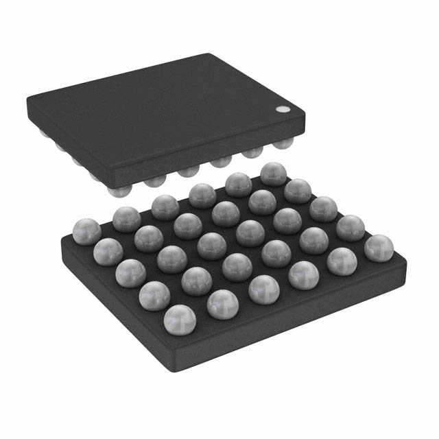
The MAX30001 is available in a 30-bump wafer-level
package (WLP), operating over the 0°C to +70°C commercial temperature range.
Applications
●● Single-Lead Event Monitors for Arrhythmia Detection
●● Single-Lead Wireless Patches for
In-Patient/Out-Patient Monitoring
●● Chest Band Heart Rate Monitors for Fitness
Applications
●● Bio Authentication and ECG-On-Demand Applications
●● Respiration and Hydration Monitors
●● Impedance Based Heart Rate Detection
Ordering Information appears at end of data sheet.
Benefits and Features
●● Can be Used in IEC 60601-2-47:2012 Compliant
Systems
●● Clinical-Grade ECG and BioZ AFE with High
Resolution Data Converter
• 15.9 Bits ENOB with 3.1µVP-P (typ) Noise for ECG
• 17 Bits ENOB with 1.1µVP-P Noise for BioZ
●● Better Dry Starts Due to Much Improved Real World
CMRR and High Input Impedance
• Fully Differential Input Structure with CMRR > 100dB
●● Offers Better Common-Mode to Differential Mode
Conversion Due to High Input Impedance
●● High Input Impedance > 1GΩ for Extremely Low
Common-to-Differential Mode
●● Minimum Signal Attenuation at the Input During Dry
Start Due to High Electrode Impedance
●● High DC Offset Range of ±650mV (1.8V, typ) Allows
to Be Used with Wide Variety of Electrodes
●● High AC Dynamic Range of 65mVP-P for ECG and
90mVP-P for BioZ Will Help Prevent Saturation in the
Presence of Motion/Direct Electrode Hits
●● Longer Battery Life Compared to Competing Solutions
• 85µW at 1.1V Supply Voltage for ECG
• 158µW at 1.1V Supply Voltage for BioZ
●● Leads-On Interrupt Feature Allows to Keep the µC
in Deep Sleep Mode Until Valid Lead Condition is
Detected
• Lead-On Detect Current: 0.7µA (typ)
●● Built-In Heart Rate Detection with Interrupt Feature
Eliminates the Need to Run HR Algorithm on the
µController
• Robust R-R Detection in High Motion Environment
at Extremely Low Power
●● Configurable Interrupts Allows the µC Wake-Up Only
on Every Heart Beat Reducing the Overall System
Power
●● High Accuracy Allows for More Physiological Data
Extractions
●● 32-Word ECG and 8-Word BioZ FIFOs Allows the
MCU to Stay Powered Down for 256ms with Full
Data Acquisition
●● High-Speed SPI Interface
●● Shutdown Current of 0.6µA (typ)
19-100133; Rev 2; 8/19
�MAX30001
Ultra-Low-Power, Single-Channel Integrated
Biopotential (ECG, R-to-R, and Pace Detection)
and Bioimpedance (BioZ) AFE
Functional Diagram
DVDD
AVDD
OVDD
MAX30001
PACE DETECT CHANNEL
AOUT
BUFFER
MUX
POL.
LPF
INPUT
AMP
LPF
PGA
SW.
RESPIRATION
CANCEL,
DERIVATIVE,
SAMPLE/HOLD
WINDOW
COMPARE
AND
RESYNC
PACEP
PACEN
BIOIMPEDANCE CHANNEL
BIP
BIN
CSB
HPF
ESD, EMI,
INPUT MUX,
DC LEAD
CHECK
AAF
INPUT
AMP
f-3dB
= 600Hz
-40dB/dec
-20dB/dec
20-BIT
∑Δ ADC
PGA
SELECTABLE PHASE
DRVP
DECIMATION
FILTER
20-BIT
SDI
SPI INTERFACE,
ECG FIFO,
AND
REGISTERS
CLOCK DIVIDER
w/ PHASE
ADJUST
SDO
INTB
PUSH/PULL
CURRENT
SOURCE
DRVN
SCLK
INT2B
BIOPOTENTIAL CHANNEL
ECGP
ECGN
AAF
ESD, EMI,
INPUT MUX,
DC LEAD
CHECK
INPUT
AMP
f-3dB
= 600Hz
-40dB/dec
18-BIT
∑Δ ADC
PGA
18-BIT
DECIMATION
FILTER
FAST
SETTLING
R-TO-R
DETECTOR
14-BIT
CAPP
CAPN
SUPPORT CIRCUITRY
REFERENCE
BUFFER
COMMON-MODE
BUFFER
fCLK
BIASING
BANDGAP
AGND
www.maximintegrated.com
VCM
VBG
VREF
RBIAS
PLL
CPLL
SEQUENCER
FCLK
fHFC
DGND
Maxim Integrated │ 2
�MAX30001
Ultra-Low-Power, Single-Channel Integrated
Biopotential (ECG, R-to-R, and Pace Detection)
and Bioimpedance (BioZ) AFE
Absolute Maximum Ratings
AVDD to AGND.....................................................-0.3V to +2.0V
DVDD to DGND.....................................................-0.3V to +2.0V
AVDD to DVDD.....................................................-0.3V to +0.3V
OVDD to DGND....................................................-0.3V to +3.6V
AGND to DGND....................................................-0.3V to +0.3V
CSB, SCLK, SDI, FCLK to DGND........................-0.3V to +3.6V
SDO, INTB, INT2B
to DGND......... -0.3V to the lower of (3.6V and OVDD + 0.3V)
All Other Pins
to AGND.......... -0.3V to the lower of (2.0V and AVDD + 0.3V)
Maximum Current into Any Pin.........................................±50mA
Continuous Power Dissipation (TA = +70°C)
30-Bump WLP
(derate 24.3mW/ºC above +70ºC)...........................1945.5mW
Operating Temperature Range................................0ºC to +70°C
Junction Temperature.......................................................+150°C
Storage Temperature Range............................. -65°C to +150°C
Lead Temperature (Soldering, 10sec).............................. +300°C
Soldering Temperature (reflow)........................................+260°C
Stresses beyond those listed under “Absolute Maximum Ratings” may cause permanent damage to the device. These are stress ratings only, and functional operation of the device at these
or any other conditions beyond those indicated in the operational sections of the specifications is not implied. Exposure to absolute maximum rating conditions for extended periods may affect
device reliability.
Package Information
PACKAGE TYPE: 30 WLP
Package Code
W302L2+1
Outline Number
21-100074
Land Pattern Number
Refer to Application Note 1891
THERMAL RESISTANCE, FOUR-LAYER BOARD
Junction to Ambient (θJA)
44°C/W
Package thermal resistances were obtained using the method described in JEDEC specification JESD51-7, using a four-layer board.
For detailed information on package thermal considerations, refer to www.maximintegrated.com/thermal-tutorial.
For the latest package outline information and land patterns (footprints), go to www.maximintegrated.com/packages. Note that a “+”,
“#”, or “-” in the package code indicates RoHS status only. Package drawings may show a different suffix character, but the drawing
pertains to the package regardless of RoHS status.
Electrical Characteristics
(VDVDD = VAVDD = +1.1V to +2.0V, VOVDD = +1.65V to +3.6V, fFCLK = 32.768kHz, LN_BIOZ = 1, TA = TMIN to TMAX, unless otherwise
noted. Typical values are at VDVDD = VAVDD = +1.8V, VOVDD = +2.5V, TA = +25°C.) (Note 1)
PARAMETER
SYMBOL
CONDITIONS
MIN
TYP
MAX
UNITS
ECG CHANNEL
VAVDD = +1.1V, THD < 0.3%
AC Differential Input Range
VAVDD = +1.8V, THD < 0.3%
VAVDD = +1.1V, shift from nominal gain < 2%
DC Differential Input Range
VAVDD = +1.1V, from VMID, shift from nominal
gain < 2%
0Ω source impedance, f = 64Hz, TA = +25˚C
(Note 2)
With impedance mismatch (Note 3)
www.maximintegrated.com
-300
+300
±650
-150
mVP-P
mV
+150
mV
VAVDD = +1.8V, from VMID, shift from nominal
gain < 2%
CMRR
+15
±32.5
VAVDD = +1.8V
Common Mode Input Range
Common Mode Rejection Ratio
-15
±550
100
115
dB
77
Maxim Integrated │ 3
�MAX30001
Ultra-Low-Power, Single-Channel Integrated
Biopotential (ECG, R-to-R, and Pace Detection)
and Bioimpedance (BioZ) AFE
Electrical Characteristics (continued)
(VDVDD = VAVDD = +1.1V to +2.0V, VOVDD = +1.65V to +3.6V, fFCLK = 32.768kHz, LN_BIOZ = 1, TA = TMIN to TMAX, unless otherwise
noted. Typical values are at VDVDD = VAVDD = +1.8V, VOVDD = +2.5V, TA = +25°C.) (Note 2)
PARAMETER
SYMBOL
CONDITIONS
MIN
BW = 0.05 – 150Hz, GCH = 20x
ECG Channel Input Referred
Noise
TA = +25°C
-1
Common-mode, DC
Input Impedance (INA)
ECG Channel Total Harmonic
Distortion
THD
ECG Channel Gain Setting
GCH
ECG Channel Gain Error
(Excluding Reference)
ECG Channel Offset Error
µVRMS
3.1
6.6
µVP-P
±0.1
+1
MΩ
VAVDD = +1.80V, VIN = 65mVP-P, FIN = 64Hz,
GCH = 20x, electrode offset = ±300mV
0.025
%
VAVDD = +1.1V, VIN = 30mVP-P, FIN = 64Hz,
GCH = 20x, electrode offset = ±300mV
0.3
Programmable, see ECG_GAIN[1:0]
20 to 160
-2.5
+2.5
%
VAVDD = +1.1V, GCH = 20x,
ECGP = ECGN = VMID
-4.5
+4.5
%
FHP = 1/(2π x RHPF x CHPF), CHPF =
capacitance between CAPP and CAPN
320
±0.1
% of
FSR
18
Bits
125 to
512
SPS
450
55
0.09
Fast Settling Recovery Time
CHPF = 10µF, Note: varies by sample rate,
see Table 3.
500
Digital Low-Pass Filter
Linear phase FIR filter.
ECG_RATE = 00, 01
www.maximintegrated.com
PSRR
600
kΩ
160
Fast recovery disabled
ECG Power Supply Rejection
V/V
VAVDD = +1.8V, GCH = 20x,
ECGP = ECGN = VMID
Fast recovery enabled (1.1V)
Digital High-Pass Filter
nA
1500
Fast recovery enabled (1.8V)
Analog High-Pass Filter Slew
Current
1.0
Differential, DC
Programmable, see ECG_RATE[1:0]
RHPF
µVP-P
0.46
GΩ
ADC Resolution
CAPP to CAPN Impedance
UNITS
µVRMS
45
(Note 4)
ADC Sample Rate
MAX
4.6
BW = 0.05 – 40Hz, GCH = 20x (Note 2)
Input Leakage Current
TYP
0.77
DLPF[0:1] = 01
40
DLPF[0:1] = 10
100
DLPF[0:1] = 11
150
Phase-corrected 1st-order IIR filter. DHPF = 1
0.5
Lead bias disabled, DC
107
Lead bias disabled, f = 64Hz
110
µA
ms
Hz
Hz
dB
Maxim Integrated │ 4
�MAX30001
Ultra-Low-Power, Single-Channel Integrated
Biopotential (ECG, R-to-R, and Pace Detection)
and Bioimpedance (BioZ) AFE
Electrical Characteristics (continued)
(VDVDD = VAVDD = +1.1V to +2.0V, VOVDD = +1.65V to +3.6V, fFCLK = 32.768kHz, LN_BIOZ = 1, TA = TMIN to TMAX, unless otherwise
noted. Typical values are at VDVDD = VAVDD = +1.8V, VOVDD = +2.5V, TA = +25°C.) (Note 2)
PARAMETER
SYMBOL
CONDITIONS
MIN
TYP
MAX
UNITS
ECG INPUT MUX
Pullup/
pulldown
DC Lead Off Check
DC Lead Off Comparator Low
Threshold
DC Lead Off Comparator High
Threshold
Lead Bias Impedance
Lead Bias Voltage
5
IMAG[2:0] = 010
10
IMAG[2:0] = 011
20
IMAG[2:0] = 100
50
IMAG[2:0] = 101
100
VTH[1:0] = 11 (Note 5)
VMID –
0.50
VTH[1:0] = 10 (Note 6)
VMID –
0.45
VTH[1:0] = 01 (Note 7)
VMID –
0.40
VTH[1:0] = 00
VMID –
0.30
VTH[1:0] = 11 (Note 5)
VMID +
0.50
VTH[1:0] = 10 (Note 6)
VMID +
0.45
VTH[1:0] = 01 (Note 7)
VMID +
0.40
VTH[1:0] = 00
VMID +
0.30
Lead bias enabled
VMID
IMAG[2:0] = 001
RBIASV[1:0] = 00
50
RBIASV[1:0] = 01
100
RBIASV[1:0] = 10
200
V
V
MΩ
VAVDD/
2.15
Lead bias enabled
VMAG = 0
0.25
VMAG = 1
0.50
Calibration Voltage Magnitude
Single-ended
Calibration Voltage Magnitude
Error
Single-ended (Note 8)
Calibration Voltage Frequency
Programmable, see FCAL[2:0]
Calibration Voltage Pulse Time
Programmable, see
THIGH[10:0]
www.maximintegrated.com
nA
V
mV
-3
+3
%
0.0156 to
256
Hz
FIFTY = 0
0.03052
to 62.474
ms
FIFTY = 1
50
%
Maxim Integrated │ 5
�MAX30001
Ultra-Low-Power, Single-Channel Integrated
Biopotential (ECG, R-to-R, and Pace Detection)
and Bioimpedance (BioZ) AFE
Electrical Characteristics (continued)
(VDVDD = VAVDD = +1.1V to +2.0V, VOVDD = +1.65V to +3.6V, fFCLK = 32.768kHz, LN_BIOZ = 1, TA = TMIN to TMAX, unless otherwise
noted. Typical values are at VDVDD = VAVDD = +1.8V, VOVDD = +2.5V, TA = +25°C.) (Note 2)
PARAMETER
SYMBOL
CONDITIONS
MIN
TYP
MAX
UNITS
BIOIMPEDANCE (BioZ) CHANNEL
Signal Generator Resolution
Square wave generator
DRVP/N Injected Full-Scale
Current
Programmable, see BIOZ_CGMAG[2:0]
DRVP/N Injected Current
Accuracy
Bits
8 to 96
μAPK
Internal bias resistor, see EXT_RBIAS
-30
+30
External bias resistor (0.1%, 10ppm, 324kΩ)
-10
+10
DRVP/N Injected Current
Power Supply Rejection
DRVP/N Injected Current
Temperatue Coefficient
External bias resistor, 32μAP-P, 0 to 70ºC
(0.1%, 10ppm, 324kΩ)
DRVP/N Compliance Voltage
VDRVP - VDRVN
Current Injection Frequency
Programmable, see BIOZ_FCGEN[3:0]
AC Differential Input Range
1
Shift from nominal gain < 1% (VAVDD = 1.1V)
Shift from nominal gain < 1% (VAVDD = 1.8V)
%


 工商网监
湘ICP备2023018690号
工商网监
湘ICP备2023018690号
