Evaluation Kit
Available
Design
Resources
Tools
and Models
Support
Click here to ask an associate for production status of specific part numbers.
MAX30003
Ultra-Low Power, Single-Channel Integrated
Biopotential (ECG, R-to-R Detection) AFE
General Description
The MAX30003 is a complete, biopotential, analog frontend solution for wearable applications. It offers high
performance for clinical and fitness applications, with
ultra-low power for long battery life. The MAX30003 is a
single biopotential channel providing ECG waveforms and
heart rate detection.
The biopotential channel has ESD protection, EMI filtering,
internal lead biasing, DC leads-off detection, ultra-low
power leads-on detection during standby mode, and extensive
calibration voltages for built-in self-test. Soft power-up
sequencing ensures no large transients are injected into
the electrodes. The biopotential channel also has high
input impedance, low noise, high CMRR, programmable
gain, various low-pass and high-pass filter options, and
a high resolution analog-to-digital converter. The
biopotential channel is DC coupled, can handle large
electrode voltage offsets, and has a fast recovery mode
to quickly recover from overdrive conditions, such as
defibrillation and electrosurgery.
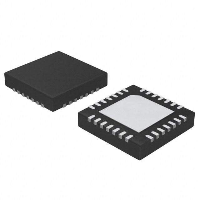
The MAX30003 is available in a 28-pin TQFN and
30-bump wafer-level package (WLP), operating over the
0°C to +70°C commercial temperature range.
Applications
●
●
●
●
Single-Lead Event Monitors for Arrhythmia Detection
Single-Lead Wireless Patches for At-Home/
In-Hospital Monitoring
Chest Band Heart Rate Monitors for Fitness Applications
Bio Authentication and ECG-On-Demand Applications
Ordering Information appears at end of data sheet.
Benefits and Features
● Clinical-Grade ECG AFE with High-Resolution Data
Converter
• 15.5 Bits Effective Resolution with 5µVP-P Noise
● Better Dry Starts Due to Much Improved Real World
CMRR and High Input Impedance
• Fully Differential Input Structure with CMRR > 100dB
● Offers Better Common-Mode to Differential Mode
Conversion Due to High Input Impedance
• High Input Impedance > 500MΩ for Extremely Low
Common-to-Differential Mode Conversion
● Minimum Signal Attenuation at the Input During Dry
Start Due to High Electrode Impedance
● High DC Offset Range of ±650mV (1.8V, typ) Allows
to Be Used with Wide Variety of Electrodes
● High AC Dynamic Range of 65mVP-P Will Help the
AFE Not Saturate in the Presence of Motion/Direct
Electrode Hits
● Longer Battery Life Compared to Competing Solutions
• 85µW at 1.1V Supply Voltage
● Leads-On Interrupt Feature Allows to Keep µC in
Deep Sleep Mode with RTC Off Until Valid Lead
Condition is Detected
• Lead-On Detect Current: 0.7µA (typ)
● Built-In Heart Rate Detection with Interrupt Feature
Eliminates the Need to Run HR Algorithm on the
µController
• Robust R-R Detection in High Motion Environment
at Extremely Low Power
● Configurable Interrupts Allows the µC Wake-Up Only on
Every Heart Beat Reducing the Overall System Power
● High Accuracy Allows for More Physiological Data
Extractions
● 32-Word FIFO Allows You to Wake Up µController
Every 256ms with Full ECG Acquisition
● High-Speed SPI Interface
● Shutdown Current of 0.5µA (typ)
19-8558; Rev 3; 9/21
© 2021 Analog Devices, Inc. All rights reserved. Trademarks and registered trademarks are the property of their respective owners.
One Analog Way, Wilmington, MA 01887 U.S.A.
|
Tel: 781.329.4700
|
© 2021 Analog Devices, Inc. All rights reserved.
�MAX30003
Ultra-Low Power, Single-Channel Integrated
Biopotential (ECG, R-to-R Detection) AFE
Functional Diagram
AVDD
DVDD
OVDD
MAX30003
ECG CHANNEL
ECGP
ECGN
AAF
ESD, EMI,
INPUT MUX ,
DC LEAD
CHECK
INPUT
AMP
PGA
CSB
18-BIT
DECIMATION
FILTER
Σ∆
ADC
SDI
f-3dB = 600Hz
-40dB/dec
SPI INTERFACE ,
FIFO, AND SETUP
REGISTERS
R TO R
DETECTOR
FAST
SETTLING
SCLK
SDO
INTB
CAPP
INT2B
CAPN
SUPPORT CIRCUITRY
COMMON -MODE
BUFFER
INPUT
AMP
BANDGAP
BIASING
PLL
fHFC
SEQUENCER
FCLK
fCLK
AGND
www.analog.com
VCM
VBG
VREF
RBIAS
CPLL
Analog Devices │ 2
�MAX30003
Ultra-Low Power, Single-Channel Integrated
Biopotential (ECG, R-to-R Detection) AFE
Absolute Maximum Ratings
AVDD to AGND......................................................-0.3V to +2.0V
DVDD to DGND.....................................................-0.3V to +2.0V
AVDD to DVDD.......................................................-0.3V to +0.3V
OVDD to DGND.....................................................-0.3V to +3.6V
AGND to DGND....................................................-0.3V to +0.3V
CSB, SCLK, SDI, FCLK to DGND........................-0.3V to +3.6V
SDO, INTB, INT2B to
DGND..............-0.3V to the lower of (3.6V and OVDD + 0.3V)
All other pins to
AGND...............-0.3V to the lower of (2.0V and AVDD + 0.3V)
Maximum Current into Any Pin.........................................±50mA
Continuous Power Dissipation (TA = +70°C)
28-Pin TQFN (derate 34.5mW/°C above +70°C)....2758.6mW
30-Bump WLP (derate 24.3mW/°C
above +70°C)......................................................1945.5mW
Operating Temperature Range................................0°C to +70°C
Junction Temperature.......................................................+150°C
Storage Temperature Range..............................-65ºC to +150°C
Lead Temperature (Soldering, 10sec).............................. +300°C
Soldering Temperature (reflow)........................................+260°C
Package Thermal Characteristics (Note 1)
TQFN
Junction-to-Ambient Thermal Resistance (θJA)...........29°C/W
Junction-to-Case Thermal Resistance (θJC)..................2°C/W
WLP
Junction-to-Ambient Thermal Resistance (θJA)...........44°C/W
Note 1: Package thermal resistances were obtained using the method described in JEDEC specification JESD51-7, using a four-layer
board. For detailed information on package thermal considerations, refer to www.maximintegrated.com/thermal-tutorial.
Stresses beyond those listed under “Absolute Maximum Ratings” may cause permanent damage to the device. These are stress ratings only, and functional operation of the device at these
or any other conditions beyond those indicated in the operational sections of the specifications is not implied. Exposure to absolute maximum rating conditions for extended periods may affect
device reliability.
Electrical Characteristics
(VDVDD = VAVDD = +1.1V to +2.0V, VOVDD = +1.65V to +3.6V, fFCLK = 32.768kHz, TA = TMIN to TMAX, unless otherwise noted. Typical
values are at VDVDD = VAVDD = +1.8V, VOVDD = +2.5V, TA = +25°C.) (Note 2)
PARAMETER
SYMBOL
CONDITIONS
MIN
VAVDD = +1.1V, THD < 0.3%
-15
TYP
MAX
UNITS
ECG CHANNEL
AC Differential Input Range
VAVDD = +1.8V, THD < 0.3%
VAVDD = +1.1V, shift from nominal gain < 2%
DC Differential Input Range
Common Mode Input Range
Common Mode Rejection
Ratio
ECG Channel Input
Referred Noise
Input Leakage Current
Input Impedance (INA)
www.analog.com
±32.5
-300
VAVDD = +1.8V
VAVDD = +1.1V, from VMID, shift from
nominal gain < 2%
0W source impedance, f = 64Hz (Note 3)
-150
105
+150
115
dB
77
BW = 0.05 - 40Hz, GCH = 20x (Note 3)
Differential, DC
mV
mV
BW = 0.05 - 150Hz, GCH = 20x
Common-mode, DC
mVp-p
±550
(Note 4)
TA = +25°C
+300
±650
VAVDD = +1.8V, from VMID, shift from
nominal gain < 2%
CMRR
+15
-1
0.82
µVRMS
5.4
µVp-p
0.53
1.0
µVRMS
3.5
6.6
µVp-p
0.1
+1
nA
45
GΩ
1500
MΩ
Analog Devices │ 3
�MAX30003
Ultra-Low Power, Single-Channel Integrated
Biopotential (ECG, R-to-R Detection) AFE
Electrical Characteristics (continued)
(VDVDD = VAVDD = +1.1V to +2.0V, VOVDD = +1.65V to +3.6V, fFCLK = 32.768kHz, TA = TMIN to TMAX, unless otherwise noted. Typical
values are at VDVDD = VAVDD = +1.8V, VOVDD = +2.5V, TA = +25°C.) (Note 2)
PARAMETER
SYMBOL
ECG Channel Total
Harmonic Distortion
THD
ECG Channel Gain Setting
GCH
ECG Channel Gain Error
ECG Channel Offset Error
CONDITIONS
MIN
VAVDD = +1.80V, VIN = 65mVp-p, FIN = 64Hz,
GCH = 20x, electrode offset = ±300mV
0.3
Programmable, see register map
20 to 160
Analog High-Pass Filter Slew
Current
-2.5
+2.5
%
VAVDD = +1.1V, GCH = 20x,
ECGP = ECGN = VMID
-4.5
+4.5
%
FHP = 1/(2R x RHPF x CHPF), CHPF =
capacitance between CAPP and CAPN
320
0.1
% of
FSR
18
Bits
125 to 512
SPS
450
Fast recovery enabled (1.8V)
160
Fast recovery enabled (1.1V)
55
Fast recovery disabled
0.09
Fast Settling Recovery Time
CHPF = 10µF, Note: varies by sample rate,
see Table 3.
500
Digital Low-Pass Filter
Linear phase
FIR filter.
Digital High-Pass Filter
Phase-corrected 1st-order IIR filter. DHPF = 1
0.5
Lead bias disabled, DC
107
Lead bias disabled, fSW = 64Hz
110
ECG Power Supply Rejection
PSRR
V/V
VAVDD = +1.8V, GCH = 20x,
ECGP = ECGN = VMID
Programmable, see register map
RHPF
UNITS
%
VAVDD = +1.1V, VIN = 30mVp-p, FIN = 64Hz,
GCH = 20x, electrode offset = ±300mV
ADC Resolution
CAPP to CAPN Impedance
MAX
0.025
(Note 5)
ADC Sample Rate
TYP
DLPF[0:1] = 01
40
DLPF[0:1] = 10
100
DLPF[0:1] = 11
150
600
kΩ
µA
ms
Hz
Hz
dB
ECG INPUT MUX
DC Lead Off Check
www.analog.com
Pullup/
pulldown
DCLOFF_IMAG[2:0] = 001
5
DCLOFF_IMAG[2:0] = 010
10
DCLOFF_IMAG[2:0] = 011
20
DCLOFF_IMAG[2:0] = 100
50
DCLOFF_IMAG[2:0] = 101
100
nA
Analog Devices │ 4
�MAX30003
Ultra-Low Power, Single-Channel Integrated
Biopotential (ECG, R-to-R Detection) AFE
Electrical Characteristics (continued)
(VDVDD = VAVDD = +1.1V to +2.0V, VOVDD = +1.65V to +3.6V, fFCLK = 32.768kHz, TA = TMIN to TMAX, unless otherwise noted. Typical
values are at VDVDD = VAVDD = +1.8V, VOVDD = +2.5V, TA = +25°C.) (Note 2)
PARAMETER
SYMBOL
DC Lead Off Comparator Low
Threshold
DC Lead Off Comparator
High Threshold
VMID
MIN
TYP
DCLOFF_VTH[1:0] = 11 (Note 6)
VMID - 0.50
DCLOFF_VTH[1:0] = 10 (Note 7)
VMID - 0.45
DCLOFF_VTH[1:0] = 01 (Note 8)
VMID - 0.40
DCLOFF_VTH[1:0] = 00
VMID - 0.30
DCLOFF_VTH[1:0] = 11 (Note 6)
VMID + 0.50
DCLOFF_VTH[1:0] = 10 (Note 7)
VMID + 0.45
DCLOFF_VTH[1:0] = 01 (Note 8)
VMID + 0.40
DCLOFF_VTH[1:0] = 00
VMID + 0.30
Lead bias
enabled
Lead Bias Impedance
Lead Bias Voltage
CONDITIONS
RBIASV[1:0] = 00
50
RBIASV[1:0] = 01
100
RBIASV[1:0] = 10
200
MAX
V
V
MΩ
VAVDD/
2.15
Lead bias enabled
VMAG = 0
0.25
VMAG = 1
0.50
Calibration Voltage
Magnitude
Single-ended
Calibration Voltage
Magnitude Error
Single-ended (Note 9)
Calibration Voltage
Frequency
Programmable, see register map
Calibration Voltage Pulse
Time
Programmable,
see register map
-2
UNITS
V
mV
+2
%
0.0156
to 256
Hz
FIFTY = 0
0.03052
to 62.474
ms
FIFTY = 1
50
%
0.650
V
100
kΩ
INTERNAL REFERENCE/COMMON-MODE
VBG Output Voltage
VBG
VBG Output Impedance
External VBG Compensation
Capacitor
CVBG
VREF Output Voltage
VREF
VREF Temperature Coefficient
TCREF
1
TA = +25°C
TA = 0°C to +70°C
VREF Buffer Line Regulation
VREF Buffer Load Regulation
www.analog.com
ILOAD = 0 to 100µA
0.995
µF
1.000
1.005
V
10
ppm/°C
330
µV/V
25
µV/µA
Analog Devices │ 5
�MAX30003
Ultra-Low Power, Single-Channel Integrated
Biopotential (ECG, R-to-R Detection) AFE
Electrical Characteristics (continued)
(VDVDD = VAVDD = +1.1V to +2.0V, VOVDD = +1.65V to +3.6V, fFCLK = 32.768kHz, TA = TMIN to TMAX, unless otherwise noted. Typical
values are at VDVDD = VAVDD = +1.8V, VOVDD = +2.5V, TA = +25°C.) (Note 2)
PARAMETER
SYMBOL
External VREF Compensation
Capacitor
CREF
VCM Output Voltage
VCM
External VCM Compensation
Capacitor
CCM
CONDITIONS
MIN
TYP
1
10
µF
0.650
V
10
µF
1
MAX
UNITS
DIGITAL INPUTS (SDI, SCLK, CSB, FCLK)
Input-Voltage High
VIH
Input-Voltage Low
VIL
0.7 ×
VOVDD
V
0.3 ×
VOVDD
V
VHYS
0.05 ×
VOVDD
V
Input Capacitance
CIN
10
pF
Input Current
IIN
Input Hysteresis
-1
+1
µA
DIGITAL OUTPUTS (SDO, INTB, INT2B)
Output Voltage High
VOH
ISOURCE = 1mA
Output Voltage Low
VOL
ISINK = 1mA
Three-State Leakage Current
VOVDD
– 0.04
V
-1
Three-State Output
Capacitance
0.4
V
+1
µA
15
pF
POWER SUPPLY
Analog Supply Voltage
VAVDD
Connect VAVDD to VDVDD
1.1
2.0
V
Digital Supply Voltage
VDVDD
Connect VDVDD to VAVDD
1.1
2.0
V
Interface Supply Voltage
VOVDD
Power for I/O drivers only
1.65
3.6
V
120
µA
Supply Current
Interface Supply Current
www.analog.com
IAVDD +
IDVDD
IOVDD
VAVDD = VDVDD = +1.1V
76
VAVDD = VDVDD = +1.8V
100
VAVDD = VDVDD = +2.0V
109
TA = +70°C
0.98
TA = +25°C
0.73
VOVDD = +1.65V, ECG channel at 512sps
(Note 10)
0.2
VOVDD = +3.6V, ECG channel at 512sps
(Note 10)
0.6
ECG
channel
ULP Lead
On Detect
2.5
µA
1.6
Analog Devices │ 6
�MAX30003
Ultra-Low Power, Single-Channel Integrated
Biopotential (ECG, R-to-R Detection) AFE
Electrical Characteristics (continued)
(VDVDD = VAVDD = +1.1V to +2.0V, VOVDD = +1.65V to +3.6V, fFCLK = 32.768kHz, TA = TMIN to TMAX, unless otherwise noted. Typical
values are at VDVDD = VAVDD = +1.8V, VOVDD = +2.5V, TA = +25°C.) (Note 2)
PARAMETER
Shutdown Current
SYMBOL
CONDITIONS
MIN
VAVDD = VDVDD T = +70°C
A
ISAVDD +
= 2.0V
ISDVDD
T
A = +25°C
(Note 5)
ISOVDD
TYP
MAX
UNITS
2.5
µA
0.79
0.51
VOVDD = +3.6V, VAVDD = VDVDD = +2.0V
1.1
ESD PROTECTION
ECGP, ECGN
IEC61000-4-2 Contact Discharge (Note 11)
±8
IEC61000-4-2 Air-Gap Discharge (Note 11)
±15
HMM
±8
kV
Timing Characteristics
(VDVDD = VAVDD = +1.1V to +2.0V, VOVDD = +1.65V to +3.6V, TA = TMIN to TMAX, unless otherwise noted. Typical values are at
VDVDD = +1.8V, VOVDD = +2.5V, TA = +25°C.) (Notes 2, 3)
PARAMETER
SYMBOL
CONDITIONS
MIN
TYP
MAX
UNITS
12
MHz
TIMING CHARACTERISTICS
SCLK Frequency
fSCLK
0
SCLK Period
tCP
83
ns
SCLK Pulse Width High
tCH
15
ns
SCLK Pulse Width Low
tCL
15
ns
CSB Fall to SCLK Rise
Setup Time
tCSS0
To 1st SCLK rising edge (RE)
15
ns
CSB Fall to SCLK Rise
Hold Time
tCSH0
Applies to inactive RE preceding 1st RE
0
ns
CSB Rise to SCLK Rise
Hold Time
tCSH1
Applies to 32nd RE, executed write
10
ns
CSB Rise to SCLK Rise
tCSA
Applies to 32nd RE, aborted write
sequence
15
ns
SCLK Rise to CSB Fall
tCSF
Applies to 32nd RE
100
ns
CSB Pulse-Width High
tCSPW
20
ns
SDI-to-SCLK Rise Setup Time
tDS
8
ns
SDI to SCLK Rise Hold Time
tDH
8
ns
CLOAD = 20pf
40
ns
20
ns
SCLK Fall to SDO Transition
tDOT
CLOAD = 20pf, VAVDD = VDVDD ≥ 1.8V,
VDVDD ≥ 2.5V
SCLK Fall to SDO Hold
tDOH
CLOAD = 20pf
www.analog.com
2
ns
Analog Devices │ 7
�MAX30003
Ultra-Low Power, Single-Channel Integrated
Biopotential (ECG, R-to-R Detection) AFE
Timing Characteristics (continued)
(VDVDD = VAVDD = +1.1V to +2.0V, VOVDD = +1.65V to +3.6V, TA = TMIN to TMAX, unless otherwise noted. Typical values are at
VDVDD = +1.8V, VOVDD = +2.5V, TA = +25°C.) (Notes 2, 3)
PARAMETER
SYMBOL
CONDITIONS
MIN
TYP
MAX
UNITS
CSB Fall to SDO Fall
tDOE
Enable time, CLOAD = 20pf
30
ns
CSB Rise to SDO Hi-Z
tDOZ
Disable time
35
ns
FCLK Frequency
fFCLK
External reference clock
32.768
kHz
30.52
µs
FCLK Period
tFP
FCLK Pulse-Width High
tFH
50% duty cycle assumed
15.26
µs
FCLK Pulse-Width Low
tFL
50% duty cycle assumed
15.26
µs
Note 2: Limits are 100% tested at TA = +25°C. Limits over the operating temperature range and relevant supply voltage range are
guaranteed by design and characterization.
Note 3: Guaranteed by design and characterization. Not tested in production.
Note 4: One electrode drive with 20 MΩ
GND
LEAD BIAS
VMID
± 0.25mV,
± 0.50mV
TO ECG
INA IP
GND
ECGP
TO ECG
INA IN
ECGN
5-100nA
GND
GND
GND
GND
VDD
GND
~50200 MΩ
± 0.25mV,
± 0.50mV
VMID
VMID
Figure 3. ECG Input MUX
www.analog.com
Analog Devices │ 15
�MAX30003
Ultra-Low Power, Single-Channel Integrated
Biopotential (ECG, R-to-R Detection) AFE
● ±8kV using the Contact Discharge method specified
in IEC61000-4-2 ESD
● ±15kV using the Air Gap Discharge method specified
in IEC61000-4-2 ESD
● ±8kV HBM
● For IEC61000-4-2 ESD protection, use 1kΩ series
resistors on ECGP and ECGN that is rated to withstand 8kV surge voltages.
DC Leads-Off Detection and ULP Leads-On Detection
The input MUX leads-off detect circuitry consists of
programmable sink/source DC current sources that allow
for DC leads-off detection, while the channel is powered
up in normal operation and an ultra-low-power (ULP)
leads-on detect while the channel is powered-down.
The MAX30003 accomplishes DC leads-off detection by
applying a DC current to pull the ECG input voltage up
to above VMID + VTH or down to below VMID - VTH. The
current sources have user selectable values of 0nA, 5nA,
10nA, 20nA, 50nA, and 100nA that allow coverage of dry
and wet electrode impedance ranges. Supported thresholds
are VMID ± 0.30V (recommended), VMID ± 0.40V, VMID ±
0.45V, and VMID ± 0.50V. A threshold of 400mV, 450mV,
and 500mV should only be used when VAVDD ≥ 1.45V,
1.55V, and 1.65V, respectively. A dynamic comparator
protects against false flags generated by the input amplifier
and input chopping. The comparator checks for a minimum
continuous violation (or threshold exceeded) of 115ms to
140ms depending on the setting of FMSTR[1:0] before
asserting any one of the LDOFF_* interrupt flags (Figure
4). See registers CNFG_GEN (0x10) and CNFG_EMUX
0x14) for configuration settings and see Table 1 for
recommended values given electrode type and supply voltage.
The ULP lead on detect operates by pulling ECGN low with
a pulldown resistance larger than 5mΩ and pulling ECGP
high with a pullup resistance larger than 15MΩ. A low-power
comparator determines if ECGP is pulled below a
predefined threshold that occurs when both electrodes
make contact with the body. When the impedance
between ECGP and ECGN is less than 20mΩ, an interrupt
LONINT is asserted, alerting the µC to a leads-on condition.
A 0nA/VMID ± 300mV selection is available allowing
monitoring of the input compliance of the INA during nonDC lead-off checks.
VDD
VTH_H
VMID
ECGP,N
VTH_L
VSS
ABOVE
THRESHOLD
BELOW
THRESHOLD
INTB
115ms
LDOFF_*H
BITS
ASSERTED
Figure 4. Lead-Off Detect Behavior
electrodes within the input common mode requirements
of the ECG channel and can drive the connected body
to the proper common mode voltage level. See register
CNFG_GEN (0x10) to select a configuration.
Isolation Switches
The series switches in the MAX30003 isolate ECGP and
ECGN pins (subject) from the internal signal path. the
series switches are disabled by default. They must be
enabled to record ECG.
Calibration Voltage Sources
Calibration voltage sources are available to provide
±0.25mV (0.5mVP-P) or ±0.5mV (1.0mVP-P) inputs to
the ECG channel with programmable frequency and duty
cycle. The sources can be unipolar/bipolar relative to VMID.
Figure 5 illustrates the possible calibration waveforms.
Frequency selections are available in 4X increments from
15.625mHz to 256Hz with selected pulse widths varying
from 30.5µs to 31.723ms and 50% duty cycle. Signals
can be single-ended, differential, or common mode. This
flexibility allows end-to-end channel-testing of the ECG
signal path.
When applying calibration voltage sources with the device
connected to a subject, the series input switches must be
disconnected so as not to drive signals into the subject.
See registers CNFG_CAL (0x12) and CNFG_EMUX
(0x14) to select configuration.
Lead Bias
The MAX30003 limits the ECGP and ECGN DC input
common mode range to VMID ±150mV. This range can be
maintained either through external/internal lead-biasing.
Internal DC lead-biasing consists of 50MΩ, 100MΩ,
or 200MΩ selectable resistors to VMID that drive the
www.analog.com
Analog Devices │ 16
�MAX30003
Ultra-Low Power, Single-Channel Integrated
Biopotential (ECG, R-to-R Detection) AFE
Table 1. Recommended Lead Bias, Current Source Values,
and Thresholds for Electrode Impedance
IDC
VTH
ELECTRODES IMPEDANCE
100kΩ 200kΩ


 工商网监
湘ICP备2023018690号
工商网监
湘ICP备2023018690号
