EVALUATION KIT AVAILABLE
MAX4968B/MAX4968C
16-Channel, Linear, High-Voltage Analog
Switches in BGA Package
General Description
The MAX4968B/MAX4968C are 16-channel, high-linearity, high-voltage (HV), bidirectional SPST analog switches
with 18Ω (typ) on-resistance. The devices are ideal
for use in applications requiring high-voltage switching
controlled by a low-voltage control signal, such as
ultrasound imaging and industrial printing. The MAX4968C
provides integrated 40kΩ bleed resistors on each switch
terminal to discharge capacitive loads. Using HVCMOS
technology, these switches combine high-voltage bilateral
MOS switches and low-power CMOS logic to provide
efficient control of high-voltage analog signals.
In typical ultrasound applications, the MAX4968B/
MAX4968C do not require a dedicated HV supply, which
implies a significant simplification of system requirements.
The negative voltage supply can be shared with the
transmitter and the positive voltage supply is typically
+12V.
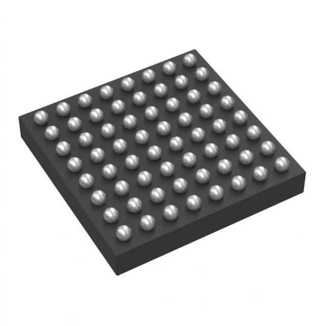
The devices are available in a 64-bump BGA package
and are specified over the -40NC to +85NC extended
temperature range.
Applications
●● Medical Ultrasound Imaging
●● Nondestructive Testing (NDT)
●● Industrial Printing
Ordering Information appears at end of data sheet.
19-7312; Rev 0; 3/14
Features
●● Save Space—Optimized for High-Channel-Count
Systems
• Small BGA Package
• 16 Integrated Channels
●● High Performance—Designed to Enhance Image
Quality
• True Linear Switching—RON Flatness Guaranteed
in Entire Input Range 46dB (typ) THD
• Low Parasitic Capacitance Guarantees High
Bandwidth
• Low-Charge Injection and Voltage Spiking
• 2nd Harmonic Distortion < -45dB at 2MHz ± 90V
Pulse Analog Class AB
• DC to 30MHz Small-Signal Analog Bandwidth
(CLOAD = 200pF)
• 500kHz to 20MHz High-Signal Analog Bandwidth
(CLOAD = 200pF)
• Extended Input Range Up to 210VP-P
• -68dB (Typ) Off-Isolation at 5MHz (50Ω)
●● Increased Flexibility Saves Design Time
• No Dedicated High-Voltage Supplies Required
• Daisy-Chainable Serial Interface
• Asynchronous Set/Clear Input to Program All
Switches Without Need for SPI
●● Superior Reliability
• Latch-Free SOI HVCMOS Process Technology for
High Performance and Robustness
• Integrated Overvoltage Protection
�MAX4968B/MAX4968C
16-Channel, Linear, High-Voltage Analog Switches
in BGA Package
Absolute Maximum Ratings
(All voltages referenced to GND.)
VDD Logic Supply Voltage ......................................-0.3V to +6V
VP-P Supply Voltage .............................................-0.3V to +13V
VNN Negative Supply Voltage .............................+0.3V to -200V
VCC10 Input Voltage............. -0.3V to MAX (12V to VP-P + 0.3V)
Logic Inputs Voltage (CLK, DIN, LE, CLR, SET) ....-0.3V to +6V
Logic Output Voltage (DOUT) .................. -0.3V to (VDD + 0.3V)
Analog Signal Range (SW_) ........(VNN - 0.3V) to (VNN + 214V)
Continuous Power Dissipation (TA = +70NC)
64-bump BGA (derate 30.30mW/NC above +70NC)...1969.7mW
Operating Temperature Range............................ -40NC to +85NC
Storage Temperature Range............................. -65NC to +150NC
Junction Temperature...................................................... +150NC
Lead Temperature (soldering, 10s).................................. +300NC
Soldering Temperature (reflow)........................................+260NC
Stresses beyond those listed under “Absolute Maximum Ratings” may cause permanent damage to the device. These are stress ratings only, and functional operation of the device at these
or any other conditions beyond those indicated in the operational sections of the specifications is not implied. Exposure to absolute maximum rating conditions for extended periods may affect
device reliability.
Package Thermal Characteristics (Note 1)
Junction-to-Ambient Thermal Resistance (BJA)..............3.3NC/W
Note 1: Package thermal resistances were obtained using the method described in JEDEC specification JESD51-7, using a four-layer
board. For detailed information on package thermal considerations, refer to www.maximintegrated.com/thermal-tutorial.
Electrical Characteristics
(VDD = +2.37V to +5.5V, VP-P = +10V to +12.5V, VNN = 0 to -200V, TA = TMIN to TMAX, unless otherwise noted. Typical values are VDD =
+3.3V, VNN = -100V, VP-P = +12V at TA = +25NC.) (Note 2)
PARAMETER
SYMBOL
CONDITIONS
MIN
TYP
MAX
UNITS
5.5
V
POWER SUPPLIES
VDD Logic Supply Voltage
VDD
2.37
VNN Supply Voltage
VNN
-200
VP-P Supply Voltage
VP-P
10
VDD Static Current
IDDS
0
V
12
12.5
V
25
50
µA
100
200
µA
VDD Dynamic Current
IDD
VDD = +5V, fCLK = 5MHz,
fDIN = 2.5MHz
VNN Static Current
INNS
All switches remain on or off,
SW_ = GND
15
25
µA
VNN Supply Dynamic Current
(All Channel Switching
Simultaneously)
INN
VP-P = +12V, VNN = -100V,
fTURN_ON/OFF = 50kHz, SW_ = GND
4.3
8
mA
VP-P Supply Static Current
IPPS
All switches remain on or off,
SW_ = GND
75
160
µA
IPP
VP-P = +12V, VNN = -100V,
fTURN_ON/OFF = 50kHz, SW_ = GND
5.4
9
mA
VCC10 Static Output Voltage
VCC10s
VP-P = +12V, all switches remain on or
off, SW_ = GND
10
10.5
V
VCC10 Dynamic Output
Voltage
VCC10
VP-P = +12V, IOUT = 30mA
9.5
10.25
V
VP-P Supply Dynamic Current
(All Channel Switching
Simultaneously)
www.maximintegrated.com
Maxim Integrated │ 2
�MAX4968B/MAX4968C
16-Channel, Linear, High-Voltage Analog Switches
in BGA Package
Electrical Characteristics (continued)
(VDD = +2.37V to +5.5V, VP-P = +10V to +12.5V, VNN = 0 to -200V, TA = TMIN to TMAX, unless otherwise noted. Typical values are
VDD = +3.3V, VNN = -100V, VP-P = +12V at TA = +25NC.) (Note 2)
PARAMETER
SYMBOL
CONDITIONS
MIN
TYP
MAX
UNITS
VNN
+210
V
34
Ω
SWITCH CHARACTERISTICS
Analog Dynamic Signal Range
VSW_
AC operation only, f > 500kHz
Small-Signal
On-Resistance
RONS
VP-P = +12V, VNN = -100V, VSW_ = 0V,
ISW_ = 5mA
18
VP-P = +12V, VNN = -100V,
ISW_ = 5mA
3
%
2
%
Small-Signal
On-Resistance Matching
ΔRONS
Small-Signal
On-Resistance Flatness
RONF
AC measured, fSW = 0.5MHz,
VSW = 80VP-P, RLOAD = 50Ω,
VP-P = +12V, VNN = -100V
Output Switch Bleed Resistor
RINT
MAX4968C only
Switch-Off Leakage
ISW_(OFF)
VNN
30
VSW = 0V, switch off (MAX4968B only)
40
50
kΩ
0
1
ΩA
Switch-Off DC Offset
RL = 100kΩ on both sides
-15
+15
mV
Switch-On DC Offset
RL = 100kΩ on both sides
-15
+15
mV
Switch Output Isolation Diode
Current
300ns pulse width, 2% duty cycle
3.0
A
SWITCH DYNAMIC CHARACTERISITICS
Turn-On Time
tON
VSW_ = +1V, RL = 100Ω, VNN = -100V,
from SET to VSW_ = +0.9V
2
5
µs
Turn-Off Time
tOFF
VSW_ = +1V, RL = 100Ω, VNN = -100V,
from CLR to VSW_ = +0.9V
2
3.5
µs
Maximum VSW_ Slew Rate
dV/dt
CL = 100pF
Off-Isolation
VISO
f = 5MHz, RL = 50Ω
-68
dB
VCT
f = 5MHz, RL = 50Ω
-69
dB
8
pF
Crosstalk
20
V/ns
SW_ Off-Capacitance
CSW_(OFF)
f = 1MHz, small signal close to zero
SW_ On-Capacitance
CSW_ (ON)
f = 1MHz, small signal close to zero
Output Voltage Spike
VSPK
RL = 50Ω
Large-Signal Analog
Bandwidth (-3dB)
fBW_L
CLOAD = 200pF, 60V amplitude
sinusoidal burst, 1% duty cycle
30
MHz
Small-Signal Analog Bandwidth
(-3dB)
fBW_S
CLOAD = 200pF, 100mV amplitude
sinusoidal
50
MHz
VNN = -100V, Figure 1
150
pC
Charge Injection
Q
14
-150
pF
+150
mV
LOGIC LEVELS
Logic-Input Low Voltage
VIL
Logic-Input High Voltage
VIH
Logic-Output Low Voltage
VOL
www.maximintegrated.com
0.75
VDD 0.75
ISINK = 1mA
V
V
0.4
V
Maxim Integrated │ 3
�MAX4968B/MAX4968C
16-Channel, Linear, High-Voltage Analog Switches
in BGA Package
Electrical Characteristics (continued)
(VDD = +2.37V to +5.5V, VP-P = +10V to +12.5V, VNN = 0 to -200V, TA = TMIN to TMAX, unless otherwise noted. Typical values are
VDD = +3.3V, VNN = -100V, VP-P = +12V at TA = +25NC.) (Note 2)
PARAMETER
SYMBOL
CONDITIONS
Logic-Output High Voltage
VOH
Logic-Input Capacitance
CIN
Logic-Input Leakage
IIN
-1
RPULLDOWN
65
Pulldown Resistor in SET Pin
ISOURCE = 1mA
MIN
TYP
MAX
VDD 0.4
UNITS
V
5
100
pF
+1
µA
140
kΩ
25
MHz
TIMING CHARACTERISTICS (Figure 2)
CLK Frequency
fCLK
DIN-to-CLK Setup Time
tDS
4
ns
DIN-to-CLK Hold Time
tDH
4
ns
CLK to LE Setup Time
tCS
28
ns
LE Low Pulse Width
tWL
12
ns
CLR High Pulse Width
tWC
16
ns
SET High Pulse Width
tWS
16
CLK Rise and Fall Times
tR, tF
CLK to DOUT Delay
tDO
ns
50
VDD = +5V ±10%, CDOUT = 15pF
28
VDD = +2.5V ±5%, CDOUT = 15pF
45
ns
ns
Note 2: All devices are 100% tested at TA = +85NC. Limits over the operating temperature range are guaranteed by design.
www.maximintegrated.com
Maxim Integrated │ 4
�MAX4968B/MAX4968C
16-Channel, Linear, High-Voltage Analog Switches
in BGA Package
Pin Test Circuits/Timing Diagrams
1V
SW_A
SW_B
ILEAK
SW_A
VOUT
ILEAK
A
RL
100kΩ
VPP
VPP
VDD
VNN
VNN
GND
SW_B
MAX4968B
MAX4968C
5V
MAX4968B
MAX4968C
VPP
VPP
VDD
VNN
VNN
GND
SWITCH-OFF LEAKAGE
5V
VPP
VPP
VDD
VNN
VNN
GND
5V
tON/tOFF TEST CIRCUIT
DC OFFSET ON/OFF
VIN = 10VP-P
AT 5MHz
VIN = 10VP-P
AT 5MHz
SW_A
SW_A
VOUT
IID
SW_B
VOUT
SW_A
VOUT
SW_B
A
MAX4968B
MAX4968C
RL
100Ω
RL
SW_B
MAX4968B
MAX4968C
SW_A
SW_B
SW_B
VPP
VPP
VDD
VNN
GND
5V
MAX4968B
MAX4968C
VPP
VPP
VDD
VNN
VNN
GND
5V
VPP
VPP
VDD
VNN
VNN
GND
ISOLATION DIODE
CURRENT
VOUT
VIN
50Ω
50Ω
MAX4968B
MAX4968C
VNN
VISO = 20log
VNN
SW_A
VCT = 20log
5V
VOUT
VIN
CROSSTALK
OFF-ISOLATION
+VSPK
VOUT
SW_A
VOUT
SW_A
VOUT
-VSPK
100pF
50Ω
SW_B
VCOM_
SW_B
MAX4968B
MAX4968C
VPP
VPP
VDD
VNN
VNN
GND
RL
1kΩ
5V
VPP
VPP
VNN
VNN
Q = 1000pF x VOUT
CHARGE INJECTION
VIN
SW_A
SW_B
MAX4968B
MAX4968C
VDD
5V
GND
OUTPUT VOLTAGE SPIKE
VOUT
VIN
SW_A
SW_B
VOUT
200pF
MAX4968B
MAX4968C
VPP
VPP
VDD
VNN
VNN
GND
SMALL-SIGNAL
BANDWIDTH MEASUREMENT
200pF
60VP-P BURST
(1% DUTY CYCLE)
10mVP-P
5V
MAX4968B
MAX4968C
VPP
VPP
VDD
VNN
VNN
GND
5V
LARGE-SIGNAL
BANDWIDTH MEASUREMENT
Figure 1. Test Circuits
www.maximintegrated.com
Maxim Integrated │ 5
�MAX4968B/MAX4968C
DIN
16-Channel, Linear, High-Voltage Analog Switches
in BGA Package
DN+1
DN
50%
LE
50%
DN-1
50%
50%
tWL
tCS
50%
CLK
50%
tDH
tDS
tDO
50%
DOUT
SWITCH
tOFF
OFF
10%
ON
CLR
tON
90%
50%
50%
tWC
SET
50%
50%
tWS
Figure 2. Serial Interface Timing
www.maximintegrated.com
Maxim Integrated │ 6
�MAX4968B/MAX4968C
16-Channel, Linear, High-Voltage Analog Switches
in BGA Package
Typical Operating Characteristics
(VDD = +3V, VP-P = +12V, VNN = -100V, RL = 100Ω, CL = 100pF, TA = +25NC, unless otherwise noted.)
TURN-ON/TURN-OFF TIME
vs. TEMPERATURE toc01
0
tON
2
-40
-60
-80
1
SWITCH-OFF LEAKAGE CURRENT
vs. TEMPERATURE
toc03
40
LEAKAGE CURRENT (nA)
3
0
toc02
-20
4
ISOLATION (dB)
TURN-ON/TURN-OFF TIME (µs)
5
ISOLATION vs.
FREQUENCY
30
20
10
-100
tOFF
-40
-15
10
35
60
85
-120
1
10
TEMPERATURE (°C)
-40
-15
toc04
POSITIVE AND NEGATIVE
POWER-SUPPLY
CURRENT vs. TEMPERATUREtoc05
100
10
35
60
85
TEMPERATURE (°C)
FREQUENCY (MHz))
LOGIC SUPPLY CURRENT
vs. SUPPLY VOLTAGE
40
0
100
LOGIC SUPPLY CURRENT vs.
SERIAL CLOCK FREQUENCYtoc06
600
TA = +85°C
TA = +25°C
20
TA = -40°C
10
0
IDD SUPPLY CURRENT (µA)
30
SUPPLY CURRENT (µA)
IDD SUPPLY CURRENT (µA)
fDIN = fCLK/2
80
VP-P = 12V
60
40
VNN = -100V, -70V, -40V
20
2.3
3.1
3.9
4.7
0
5.5
VP-P SUPPLY CURRENT vs.
SWITCHING FREQUENCY
TA = +85°C
200
TA = -40°C
-40
-15
VDD SUPPLY VOLTAGE (V)
8
TA = +25°C
400
10
35
60
0
85
0
TEMPERATURE (°C)
toc07
VNN SUPPLY CURRENT vs.
SWITCHING FREQUENCY
8
ALL SWITCHES SWITCHING
2
4
6
8
10
CLOCK FREQUENCY (MHz)
toc08
CROSSTALK vs.
FREQUENCY
0
ALL SWITCHES SWITCHING
toc09
TA = +25°C
TA = +85°C
4
2
6
TA = +25°C
TA = +85°C
4
2
TA = -40°C
0
0
10
20
30
40
CLR SWITCHING FREQUENCY (kHz)
www.maximintegrated.com
CROSSTALK (dB)
SUPPLY CURRENT (µA)
SUPPLY CURRENT (µA)
-20
6
0
0
10
20
30
40
CLR SWITCHING FREQUENCY (kHz)
-60
-80
-100
TA = -40°C
50
-40
50
-120
1
10
100
FREQUENCY (MHz))
Maxim Integrated │ 7
�MAX4968B/MAX4968C
16-Channel, Linear, High-Voltage Analog Switches
in BGA Package
Pin Configuration
TOP VIEW
(BUMPS ON BOTTOM)
MAX4968B
MAX4968C
1
2
3
4
5
6
7
8
A
SW5A
SW5B
SW6B
SW7B
SW8B
SW9B
SW10B
SW10A
B
SW4B
SW4A
SW6A
SW7A
SW8A
SW9A
SW11A
SW11B
C
SW3A
SW3B
N.C.
N.C.
N.C.
N.C.
SW12B
SW12A
D
SW2A
SW2B
N.C.
N.C.
N.C.
N.C.
SW13B
SW13A
E
SW1A
SW1B
N.C.
N.C.
N.C.
N.C.
SW14B
SW14A
F
SW0B
SW0A
N.C.
N.C.
N.C.
N.C.
SW15B
SW15A
G
N.C.
N.C.
VPP
GND
CLK
CLR
N.C.
N.C.
H
VNN
N.C.
VCC10
VDD
DIN
LE
DOUT
SET
+
7mm x 7mm
(64-BUMP BGA)
www.maximintegrated.com
Maxim Integrated │ 8
�MAX4968B/MAX4968C
16-Channel, Linear, High-Voltage Analog Switches
in BGA Package
Pin Description
PIN
NAME
FUNCTION
A1
SW5A
Analog Switch 5–Terminal
A2
SW5B
Analog Switch 5 – Terminal
A3
SW6B
Analog Switch 6 – Terminal
A4
SW7B
Analog Switch 7 – Terminal
A5
SW8B
Analog Switch 8 – Terminal
A6
SW9B
Analog Switch 9 – Terminal
A7
SW10B
Analog Switch 10 – Terminal
A8
SW10A
Analog Switch 10 – Terminal
C3-C6, D3-D6,
E3-E6, F3-F6, G1,
G2, G7, G8, H2
N.C.
B1
SW4B
Analog Switch 4 – Terminal
B2
SW4A
Analog Switch 4 – Terminal
B3
SW6A
Analog Switch 6 – Terminal
B4
SW7A
Analog Switch 7 – Terminal
B5
SW8A
Analog Switch 8 – Terminal
B6
SW9A
Analog Switch 9 – Terminal
B7
SW11A
Analog Switch 11 – Terminal
No Connection. Not connected internally.
B8
SW11B
Analog Switch 11 – Terminal
C1
SW3A
Analog Switch 3 – Terminal
C2
SW3B
Analog Switch 3 – Terminal
C7
SW12B
Analog Switch 12 – Terminal
C8
SW12A
Analog Switch 12 – Terminal
D1
SW2A
Analog Switch 2 – Terminal
D2
SW2B
Analog Switch 2 – Terminal
D7
SW13B
Analog Switch 13 – Terminal
D8
SW13A
Analog Switch 13 – Terminal
E1
SW1A
Analog Switch 1 – Terminal
E2
SW1B
Analog Switch 1 – Terminal
E7
SW14B
Analog Switch 14 – Terminal
E8
SW14A
Analog Switch 14 – Terminal
F1
SW0B
Analog Switch 0 – Terminal
F2
SW0A
Analog Switch 0 – Terminal
F7
SW15B
Analog Switch 15 – Terminal
F8
SW15A
Analog Switch 15 – Terminal
G3
VPP
www.maximintegrated.com
Positive Voltage Supply. Bypass VP-P to GND with a 0.1µF or greater ceramic
capacitor.
Maxim Integrated │ 9
�MAX4968B/MAX4968C
16-Channel, Linear, High-Voltage Analog Switches
in BGA Package
Pin Description (continued)
PIN
NAME
FUNCTION
G4
GND
Ground
G5
CLK
Serial-Clock Input
G6
CLR
Latch Clear Input
H1
VNN
Negative High-Voltage Supply. Bypass VNN to GND with a 0.1µF or greater
ceramic capacitor.
H3
VCC10
+10V LDO Output. Bypass VCC10 to GND with a 0.1µF or greater ceramic
capacitor.
H4
VDD
Logic Supply Voltage. Bypass VDD to GND with a 0.1µF or greater ceramic
capacitor.
H5
DIN
Serial-Data Input
H6
LE
Active-Low Latch-Enable Input
H7
DOUT
H8
SET
Serial-Data Output
Latch-Set Input. Pulldown resistor 100kΩ.
Detailed Description
The MAX4968B/MAX4968C are 16-channel, highlinearity, high-voltage, bidirectional SPST analog switches
with 18Ω (typ) on-resistance. The devices are ideal
for use in applications requiring high-voltage switching
controlled by a low-voltage control signal, such as
ultrasound imaging and industrial printing. The MAX4968C
provides integrated 40kΩ bleed resistors on each switch
terminal to discharge capacitive loads. Using HVCMOS
technology, these switches combine high-voltage,
bilateral MOS switches and low-power CMOS logic to
provide efficient control of high-voltage analog signals.
Low-voltage signals (VP-P < 10V) continuous wave
bipolar transmission is supported for frequencies greater
than 500kHz. For very small signals, such as the small
echoes in typical ultrasound imaging systems (VP-P <
10V), the devices are not limited to a low-frequency bandwidth and can transmit DC signals.
Voltage Supplies
The devices operate with a high voltage supply VNN from
-200V to 0, VP-P supply of +12V (typ), and a logic supply
VDD (+2.37V to +5.5V).
Bleed Resistors (MAX4968C)
In typical ultrasound applications, the MAX4968B/
MAX4968C do not require a dedicated HV supply, which
implies a significant simplification of system requirements.
The negative voltage supply can be shared with the transmitter and the positive voltage supply is typically +12V.
The MAX4968C features integrated 40kΩ bleed resistors
to discharge capacitive loads such as piezoelectric transducers. Each analog switch terminal is connected to GND
with a bleed resistor.
Analog Switch
The MAX4968B/MAX4968C are controlled by a serial
interface with a 16-bit serial shift register and transparent
latch. Each of the 16 data bits controls a single analog
switch (see Table 1). Data on DIN is clocked with the most
significant bit (MSB) first into the shift register on the rising edge of CLK. Data is clocked out of the shift register
onto DOUT on the rising edge of CLK. DOUT reflects the
status of DIN, delayed by 16 clock cycles (see Figure 2
and Figure 3).
The devices can transmit analog signals up to 210VP-P,
with an analog signal range from VNN to VNN + 210V.
Before starting the high-voltage burst transmission (VP-P
> +20V), the input voltage must be close to GND to allow
a proper settling of the pass FET. The high-voltage burst
frequency must be greater than 500kHz.
Extremely long high-voltage bursts (VP-P > 10V) with duty
cycle greater than 20% could result in signal degradation,
especially for unipolar transmission. In general, this applies
for burst transmission with a nonzero DC content.
www.maximintegrated.com
Serial Interface
Maxim Integrated │ 10
�MAX4968B/MAX4968C
16-Channel, Linear, High-Voltage Analog Switches
in BGA Package
Latch Enable (LE)
Drive LE logic-low to change the contents of the latch and
update the state of the high-voltage switches (Figure 3);
drive LE logic-high to freeze the contents of the latch and
prevent changes to the switch states. To reduce noise
due to clock feedthrough, drive LE logic-high while data is
clocked into the shift register. After the data shift register
is loaded with valid data, pulse LE logic-low to load the
contents of the shift register into the latch.
Latch Clear (CLR)
The MAX4968B/MAX4968C feature a latch-clear input.
Drive CLR logic-high to reset the contents of the latch
to zero and open all switches simultaneously. CLR does
not affect the contents of the data shift register. Pulse LE
logic-low to reload the contents of the shift register into
the latch.
Latch Set (SET)
The MAX4968B/MAX4968C feature a latch-set input.
Drive SET logic-high to set the contents of the latch to
logic-high and close all switches simultaneously. SET
does not affect the contents of the data shift register.
Pulse LE logic-low to reload the contents of the shift
register into the latch. CLR is dominant with respect to
SET.
Power-On Reset
The MAX4968B/MAX4968C feature a power-on-reset
circuit to ensure all switches are open at power-on. The
internal 16-bit serial shift register and latch are set to zero
on power-up.
LE
CLK
D15
DIN
D14
D13
D1
LSB
MSB
DOUT
D15
D0
D14
D13
D1
D0
D15
DATA FROM PREVIOUS DATA BYTE
POWER-UP DEFAULT: D[15:0] = 0
Figure 3. Latch-Enable Interface Timing
www.maximintegrated.com
Maxim Integrated │ 11
�MAX4968B/MAX4968C
16-Channel, Linear, High-Voltage Analog Switches
in BGA Package
Table 1. Serial Interface Programming (Notes 3–8)
DATA BITS
D0
(LSB)
D1
D2
D3
D4
CONTROL BITS
D5
D6
D7
LE
CLR SET
FUNCTION
SW0
SW1
SW2
SW3
L
L
L
L
OFF
H
L
L
L
ON
L
L
L
L
OFF
H
L
L
L
ON
L
L
L
OFF
L
L
L
ON
L
L
L
OFF
ON
L
H
L
H
SW4
SW5
SW6
L
L
L
L
L
L
L
OFF
H
L
L
L
ON
L
L
L
L
OFF
H
L
L
L
ON
L
L
L
L
OFF
H
L
L
L
ON
L
L
L
L
SW7
OFF
H
L
L
L
X
X
X
X
X
X
X
X
H
L
L
X
X
X
X
X
X
X
X
X
H
X
OFF
OFF
OFF
OFF
OFF
OFF
OFF
OFF
X
X
X
X
X
X
X
X
X
L
H
ON
ON
ON
ON
ON
ON
ON
ON
DATA BITS
D8
D9
D10
D11
D12
ON
HOLD PREVIOUS STATE
CONTROL BITS
D13
L
H
L
H
D14
D15
(MSB)
LE
CLR SET
FUNCTION
SW8
SW9
L
L
L
OFF
L
L
L
ON
L
L
L
OFF
ON
SW10 SW11 SW12 SW13 SW14 SW15
L
L
L
L
L
L
L
OFF
H
L
L
L
ON
L
L
L
L
OFF
H
L
L
L
ON
L
L
L
L
OFF
H
L
L
L
ON
L
L
L
L
www.maximintegrated.com
OFF
Maxim Integrated │ 12
�MAX4968B/MAX4968C
16-Channel, Linear, High-Voltage Analog Switches
in BGA Package
Table 1. Serial Interface Programming (Notes 3–8) (continued)
DATA BITS
D8
D9
D10
D11
D12
CONTROL BITS
D13
D14
D15
(MSB)
H
LE
CLR SET
FUNCTION
SW8
SW9
SW10 SW11 SW12 SW13 SW14 SW15
L
L
L
ON
L
L
L
L
OFF
H
L
L
L
ON
L
L
L
L
OFF
H
L
L
L
ON
L
X
X
X
X
X
X
X
X
H
L
HOLD PREVIOUS STATE
X
X
X
X
X
X
X
X
X
H
X
OFF
OFF
OFF
OFF
OFF
OFF
OFF
OFF
X
X
X
X
X
X
X
X
X
L
H
ON
ON
ON
ON
ON
ON
ON
ON
X = Don’t care.
Note 3: The 16 switches operate independently.
Note 4: Serial data is clocked in on the rising edge of CLK.
Note 5: The switches go to a state retaining their present condition on the rising edge of LE. When LE is low, the shift register data
flows through the latch.
Note 6: DOUT is high when switch 15 is on.
Note 7: Shift register clocking has no effect on the switch states if LE is high.
Note 8: The CLR input overrides all other inputs.
Applications Information
the subsequent device in the chain. Connect CLK, LE,
CLR, and SET inputs of all devices, and drive LE logiclow to update all devices simultaneously. Drive CLR high
to open all the switches simultaneously. Drive SET high
to close all the switches simultaneously. Additional shift
registers can be included anywhere in series with the
MAX4968B/MAX4968C data-chain.
Logic Levels
Supply Sequencing and Bypassing
In typical ultrasound applications, the MAX4968B/
MAX4968C do not require dedicated high-voltage supplies;
the negative voltage supply can be shared with the transmitter and the positive voltage supply is typically +12V. See
Figure 4, Figure 5, and Figure 6 for medical ultrasound
applications.
The MAX4968B/MAX4968C digital interface inputs (CLK,
DIN, LE, CLR, and SET) operate on the VDD logic supply
voltage.
Daisy-Chaining Multiple Devices
The MAX4968B/MAX4968C do not require special
sequencing of the VDD, VP-P and VNN supply voltages.
Bypass VDD, VP-P, and VNN to GND with a 0.1FF ceramic capacitor as close as possible to the device.
Digital output DOUT is provided to allow the connection
of multiple MAX4968B/MAX4968C devices by daisychaining (Figure 8). Connect each DOUT to the DIN of
www.maximintegrated.com
Maxim Integrated │ 13
�MAX4968B/MAX4968C
16-Channel, Linear, High-Voltage Analog Switches
in BGA Package
Application Diagrams
PROBES
MAINFRAME
HIGH-VOLTAGE TRANSMIT
1 PER CHANNEL
PROBE SELECTION
2 TO 4 PROBES
CABLE
1 PER CHANNEL
TRANSDUCERS
2 TO 4 PER CHANNEL
±1 TO 2A MAX
±100V MAX
RELAY
1 RELAY/CH/PROBE
PROBE
A
HIGH-VOLTAGE ANALOG
SWITCHES
2 TO 4 PER CHANNEL
PROBE
B
+V
10mA TYP
LOW-VOLTAGE RECEIVE
64 TO 128 CHANNELS
PROBE
C
±1V MAX
HIGHVOLTAGE
ISOLATION
-V
PROBE
D
Figure 4. Medical Ultrasound Application ─ High-Voltage Analog Switches in Probe
www.maximintegrated.com
Maxim Integrated │ 14
�MAX4968B/MAX4968C
16-Channel, Linear, High-Voltage Analog Switches
in BGA Package
PROBES
MAINFRAME
HIGH-VOLTAGE
TRANSMIT
1 PER CHANNEL
HIGH-VOLTAGE ANALOG
SWITCHES
2 TO 4 PER CHANNEL
±100V MAX
PROBE SELECTION
2 TO 4 PROBES
CABLE
TRANSDUCERS
2 TO 4 PER CHANNEL 2 TO 4 PER CHANNEL
±1 TO 2A MAX
+V
10mA TYP
LOW-VOLTAGE
RECEIVE
64 TO 128 CHANNELS
RELAYS
2 TO 4 RELAYS/CH/PROBE
PROBE
A
±1V MAX
HIGHVOLTAGE
ISOLATION
-V
PROBE
B
PROBE
C
PROBE
D
Figure 5. Medical Ultrasound Application ─ High-Voltage Analog Switches in Mainframe
www.maximintegrated.com
Maxim Integrated │ 15
�MAX4968B/MAX4968C
16-Channel, Linear, High-Voltage Analog Switches
in BGA Package
PROBES
MAINFRAME
HIGH-VOLTAGE TRANSMIT
2 TO 4 PER CHANNEL
PROBE SELECTION
2 TO 4 PROBES
CABLE
TRANSDUCERS
2 TO 4 PER CHANNEL 2 TO 4 PER CHANNEL
±1 TO 2A MAX
±100V MAX
RELAYS
2 TO 4 RELAYS/CH/PROBE
LOW-VOLTAGE RECEIVE
64 TO 128 CHANNELS
+V
PROBE
A
10mA TYP
-V
±1V MAX
PROBE
B
+V
-V
+V
-V
+V
PROBE
C
-V
+V
-V
+V
-V
PROBE
D
+V
-V
+V
-V
HIGH-VOLTAGE
ISOLATION AND
CHANNEL SELECT
2 TO 4 PER CHANNEL
Figure 6. Medical Ultrasound Application ─ Multiple Transmit and Isolation per Receiver Channel
www.maximintegrated.com
Maxim Integrated │ 16
�MAX4968B/MAX4968C
16-Channel, Linear, High-Voltage Analog Switches
in BGA Package
U11
U10
DIN1
CLK
LE
DOUT
DIN
CLK
MAX4968B
MAX4968C
DOUT
DIN
CLK
MAX4968B
MAX4968C
CLR
MAX4968B
MAX4968C
LE
CLR
SET
DOUT
DIN
CLK
LE
LE
U1n
SET
CLR
SET
CLR
SET
DIN2
U21
U20
DOUT
DIN
DIN
MAX4968B
MAX4968C
CLK
DOUT
CLR
MAX4968B
MAX4968C
CLK
LE
SET
DOUT
DIN
MAX4968B
MAX4968C
CLK
LE
U2n
LE
CLR SET
CLR
Figure 7. Interfacing Multiple Devices by Daisy-Chaining
www.maximintegrated.com
Maxim Integrated │ 17
�MAX4968B/MAX4968C
16-Channel, Linear, High-Voltage Analog Switches
in BGA Package
Functional Diagram
VDD
CLR
SET
VPP
SW0B
LEVEL
SHIFTER
LATCH
DIN
VNN
*
SW0A
VNN
16-BIT
SHIFT
REGISTER
CLK
*
MAX4968B
MAX4968C
SW15B
DOUT
*
LEVEL
SHIFTER
LATCH
VNN
SW15A
*
LE
VNN
GND
VNN
*BLEED RESISTORS AVAILABLE ON THE MAX4968C ONLY.
Ordering Information
PART
TEMP RANGE
PIN-PACKAGE
SWITCH CHANNELS
BLEED RESISTOR
MAX4968BEXB+
-40°C to +85°C
64 BGA
(7mm x 7mm)
16
No
MAX4968CEXB+
-40°C to +85°C
64 BGA
(7mm x 7mm)
16
Yes
+Denotes a lead(Pb)-free/RoHS-compliant package.
Chip Information
PROCESS: BiCMOS
Package Information
For the latest package outline information and land patterns
(footprints), go to www.maximintegrated.com/packages. Note
that a “+”, “#”, or “-” in the package code indicates RoHS status
only. Package drawings may show a different suffix character, but
the drawing pertains to the package regardless of RoHS status.
www.maximintegrated.com
PACKAGE
TYPE
PACKAGE
CODE
OUTLINE
NO.
LAND
PATTERN NO.
64 BGA
X6477+2
21-0461
Refer to
Application
Note 1891
Maxim Integrated │ 18
�MAX4968B/MAX4968C
16-Channel, Linear, High-Voltage Analog Switches
in BGA Package
Revision History
REVISION
NUMBER
REVISION
DATE
0
3/14
DESCRIPTION
Initial release
PAGES
CHANGED
—
For pricing, delivery, and ordering information, please contact Maxim Direct at 1-888-629-4642, or visit Maxim’s website at www.maximintegrated.com.
Maxim Integrated cannot assume responsibility for use of any circuitry other than circuitry entirely embodied in a Maxim Integrated product. No circuit patent licenses
are implied. Maxim Integrated reserves the right to change the circuitry and specifications without notice at any time. The parametric values (min and max limits)
shown in the Electrical Characteristics table are guaranteed. Other parametric values quoted in this data sheet are provided for guidance.
Maxim Integrated and the Maxim Integrated logo are trademarks of Maxim Integrated Products, Inc.
© 2014 Maxim Integrated │ 19
�MAX4968B/MAX4968C
www.maximintegrated.com
16-Channel, Linear, High-Voltage Analog Switches
in BGA Package
Maxim Integrated │ 20
�


 工商网监
湘ICP备2023018690号
工商网监
湘ICP备2023018690号
