MAX5700/MAX5701/
MAX5702
Ultra-Small, Dual-Channel, 8-/10-/12-Bit Buffered
Output DACs with Internal Reference
and SPI Interface
General Description
The MAX5700/MAX5701/MAX5702 2-channel, low-power,
8-/10-/12-bit, voltage-output digital-to-analog converters
(DACs) include output buffers and an internal reference
that is selectable to be 2.048V, 2.500V, or 4.096V. The
MAX5700/MAX5701/MAX5702 accept a wide supply
voltage range of 2.7V to 5.5V with extremely low power
(1.5mW) consumption to accommodate most low-voltage
applications. A precision external reference input allows
rail-to-rail operation and presents a 100kI (typ) load to
an external reference.
The MAX5700/MAX5701/MAX5702 have an a 50MHz
3-wire SPI/QSPI™/MICROWIRE®/DSP-compatible serial
interface. The DAC output is buffered and has a low supply current of less than 250FA per channel and a low
offset error of Q0.5mV (typ). On power-up, the MAX5700/
MAX5701/MAX5702 reset the DAC outputs to zero, providing additional safety for applications that drive valves
or other transducers which need to be off on power-up.
The internal reference is initially powered down to allow
use of an external reference. The MAX5700/MAX5701/
MAX5702 allow simultaneous output updates using software LOAD commands.
A clear logic input (CLR) allows the contents of the CODE
and the DAC registers to be cleared asynchronously and
sets the DAC outputs to zero. The MAX5700/MAX5701/
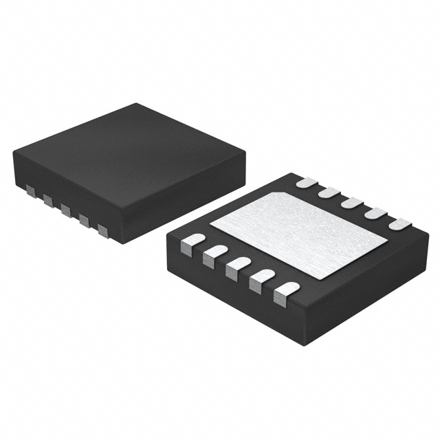
MAX5702 are available in a 10-pin µMAXM and an ultrasmall, 10-pin TDFN package and are specified over the
-40NC to +125NC temperature range.
Applications
Benefits and Features
●● Two High-Accuracy DAC Channels
• 12-Bit Accuracy Without Adjustment
• ±1 LSB INL Buffered Voltage Output
• Monotonic Over All Operating Conditions
• Independent Mode Settings for Each DAC
●● Three Precision Selectable Internal References
• 2.048V, 2.500V, or 4.096V
●● Internal Output Buffer
• Rail-to-Rail Operation with External Reference
• 4.5μs Settling Time
• Outputs Directly Drive 2kΩ Loads
●● Small 5mm x 3mm 10-Pin μMAX or Ultra-Small
3mm x 3mm 10-Pin TDFN Package
●● Wide 2.7V to 5.5V Supply Range
●● Separate 1.8V to 5.5V VDDIO Power-Supply Input
●● 50MHz 3-Wire SPI/QSPI/MICROWIRE/DSP
Compatible Serial Interface
●● Power-On-Reset to Zero-Scale DAC Output
●● CLR For Asynchronous Control
●● Three Software-Selectable Power-Down Output
Impedances
• 1kΩ, 100kΩ, or High Impedance
●● Low 350μA Supply Current at 3V VDD
Functional Diagram
Programmable Voltage and Current Sources
VDD
VDDIO
Gain and Offset Adjustment
Automatic Tuning and Optical Control
Power Amplifier Control and Biasing
Process Control and Servo Loops
Portable Instrumentation
CSB
1 OF 2 DAC CHANNELS
SCLK
CODE
REGISTER
DIN
CLR
19-6455; Rev 2; 8/13
DAC
LATCH
8 -/10-/12-BIT
DAC
OUTA
BUFFER
SPI SERIAL
INTERFACE
OUTB
CODE
Ordering Information appears at end of data sheet.
MICROWIRE is a registered trademark of National
Semiconductor Corporation.
µMAX is a registered trademark of Maxim Integrated Products, Inc.
MAX5700
MAX5701
MAX5702
INTERNAL REFERENCE/
EXTERNAL BUFFER
Data Acquisition
QSPI is a trademark of Motorola, Inc.
REF
CLEAR/
RESET
LOAD
CLEAR/
RESET
DAC CONTROL LOGIC
POR
GND
100kI
POWER-DOWN
1kI
�MAX5700/MAX5701/
MAX5702
Ultra-Small, Dual-Channel, 8-/10-/12-Bit Buffered
Output DACs with Internal Reference
and SPI Interface
Absolute Maximum Ratings
VDD, VDDIO to GND................................................. -0.3V to +6V
OUT_, REF to GND....-0.3V to the lower of (VDD + 0.3V) and +6V
CSB, SCLK, CLR to GND......................................... -0.3V to +6V
DIN to GND..................................................-0.3V to the lower of
(VDDIO + 0.3V) and +6V
Continuous Power Dissipation (TA = +70NC)
µMAX (derate at 8.8mW/NC above 70NC).....................707mW
TDFN (derate at 24.4mW/NC above 70NC).................1951mW
Maximum Continuous Current into Any Pin..................... Q50mA
Operating Temperature Range......................... -40NC to +125NC
Storage Temperature Range............................. -65NC to +150NC
Lead Temperature (soldering, 10s).................................+300NC
Soldering Temperature (reflow)..................................... +260NC
Stresses beyond those listed under “Absolute Maximum Ratings” may cause permanent damage to the device. These are stress ratings only, and functional operation of the device at these or any other conditions beyond those indicated in the operational sections of the specifications is not implied. Exposure to absolute
maximum rating conditions for extended periods may affect device reliability.
Package Thermal Characteristics (Note 1)
µMAX
Junction-to-Ambient Thermal Resistance (θJA).........113NC/W
Junction-to-Case Thermal Resistance (θJC)................42NC/W
TDFN
Junction-to-Ambient Thermal Resistance (θJA)...........41NC/W
Junction-to-Case Thermal Resistance (θJC)..................9NC/W
Note 1: Package thermal resistances were obtained using the method described in JEDEC specification JESD51-7, using a four-layer
board. For detailed information on package thermal considerations, refer to www.maximintegrated.com/thermal-tutorial.
Electrical Characteristics
(VDD = 2.7V to 5.5V, VDDIO = 1.8V to 5.5V, VGND = 0V, CL = 200pF, RL = 2kI, TA = -40NC to +125NC, unless otherwise noted. Typical
values are at TA = +25NC.) (Note 2)
PARAMETER
SYMBOL
CONDITIONS
MIN
TYP
MAX
UNITS
DC PERFORMANCE (Note 3)
Resolution and Monotonicity
Integral Nonlinearity (Note 4)
Differential Nonlinearity (Note 4)
Offset Error (Note 5)
N
INL
DNL
MAX5700
8
MAX5701
10
MAX5702
12
MAX5700
-0.25
Q0.05
+0.25
MAX5701
-0.5
Q0.25
+0.5
MAX5702
-1
Q0. 5
+1
MAX5700
-0.25
Q0.05
+0.25
MAX5701
-0.5
Q0.1
+0.5
MAX5702
-1
Q0.2
+1
OE
-5
Q0.5
+5
GE
-1.0
Q0.1
Offset Error Drift
Gain Error (Note 5)
Gain Temperature Coefficient
Q10
With respect to VREF
Zero-Scale Error
Full-Scale Error
www.maximintegrated.com
Bits
With respect to VREF
LSB
LSB
mV
FV/NC
+1.0
%FS
ppm of
FS/NC
Q3.0
0
10
mV
-0.5
+0.5
%FS
Maxim Integrated │ 2
�MAX5700/MAX5701/
MAX5702
Ultra-Small, Dual-Channel, 8-/10-/12-Bit Buffered
Output DACs with Internal Reference
and SPI Interface
Electrical Characteristics (continued)
(VDD = 2.7V to 5.5V, VDDIO = 1.8V to 5.5V, VGND = 0V, CL = 200pF, RL = 2kI, TA = -40NC to +125NC, unless otherwise noted. Typical
values are at TA = +25NC.) (Note 2)
PARAMETER
SYMBOL
CONDITIONS
MIN
TYP
MAX
UNITS
DAC OUTPUT CHARACTERISTICS
Output Voltage Range (Note 6)
Load Regulation
No load
0
VDD
2kI load to GND
0
VDD 0.2
2kI load to VDD
0.2
VDD
VOUT = VFS/2
DC Output Impedance
VOUT = VFS/2
Maximum Capacitive Load
Handling
CL
Resistive Load Handling
RL
Short-Circuit Output Current
300
VDD = 5V Q10%,
|IOUT| P 10mA
300
VDD = 3V Q10%,
|IOUT| P 5mA
0.3
VDD = 5V Q10%,
|IOUT| P 10mA
0.3
FV/mA
I
500
2
VDD = 5.5V
DC Power-Supply Rejection
VDD = 3V Q10%,
|IOUT| P 5mA
V
pF
kI
Sourcing (output
shorted to GND)
30
Sinking (output
shorted to VDD)
50
mA
VDD = 3V Q10% or 5V Q10%
100
FV/V
Positive and negative
1.0
V/Fs
¼ scale to ¾ scale, to P 1 LSB, MAX5700
2.2
¼ scale to ¾ scale, to P 1 LSB, MAX5701
2.6
¼ scale to ¾ scale, to P 1 LSB, MAX5702
4.5
DYNAMIC PERFORMANCE
Voltage-Output Slew Rate
Voltage-Output Settling Time
SR
DAC Glitch Impulse
Major code transition
Channel-to-Channel
Feedthrough (Note 7)
External reference
3.5
Internal reference
3.3
Code = 0, all digital inputs from 0V to
VDDIO
0.2
nV*s
Startup calibration time (Note 8)
200
Fs
From power-down
50
Fs
Digital Feedthrough
Power-Up Time
www.maximintegrated.com
7
Fs
nV*s
nV*s
Maxim Integrated │ 3
�MAX5700/MAX5701/
MAX5702
Ultra-Small, Dual-Channel, 8-/10-/12-Bit Buffered
Output DACs with Internal Reference
and SPI Interface
Electrical Characteristics (continued)
(VDD = 2.7V to 5.5V, VDDIO = 1.8V to 5.5V, VGND = 0V, CL = 200pF, RL = 2kI, TA = -40NC to +125NC, unless otherwise noted. Typical
values are at TA = +25NC.) (Note 2)
PARAMETER
SYMBOL
CONDITIONS
External reference
Output Voltage-Noise Density
(DAC Output at Midscale)
82
2.048V internal
reference
f = 10kHz
102
2.5V internal
reference
f = 1kHz
125
f = 10kHz
110
4.096V internal
reference
f = 1kHz
160
f = 10kHz
145
f = 0.1Hz to 10Hz
12
2.048V internal
reference
2.5V internal
reference
76
f = 0.1Hz to 300kHz
385
f = 0.1Hz to 10Hz
14
f = 0.1Hz to 10kHz
91
f = 0.1Hz to 300kHz
450
f = 0.1Hz to 10Hz
15
f = 0.1Hz to 10kHz
99
f = 0.1Hz to 300kHz
470
f = 0.1Hz to 10Hz
16
f = 0.1Hz to 10kHz
124
f = 0.1Hz to 300kHz
490
f = 1kHz
114
99
2.048V internal
reference
f = 1kHz
175
f = 10kHz
153
2.5V internal
reference
f = 1kHz
200
f = 10kHz
174
4.096V internal
reference
f = 1kHz
295
f = 10kHz
255
f = 0.1Hz to 10Hz
13
2.048V internal
reference
2.5V internal
reference
4.096V internal
reference
www.maximintegrated.com
f = 0.1Hz to 10kHz
f = 10kHz
External reference
MAX
UNITS
90
112
External reference
Integrated Output Noise
(DAC Output at Full Scale)
TYP
f = 1kHz
4.096V internal
reference
Output Voltage-Noise Density
(DAC Output at Full Scale)
MIN
f = 10kHz
External reference
Integrated Output Noise
(DAC Output at Midscale)
f = 1kHz
f = 0.1Hz to 10kHz
94
f = 0.1Hz to 300kHz
540
f = 0.1Hz to 10Hz
19
f = 0.1Hz to 10kHz
143
f = 0.1Hz to 300kHz
685
f = 0.1Hz to 10Hz
21
f = 0.1Hz to 10kHz
159
f = 0.1Hz to 300kHz
705
f = 0.1Hz to 10Hz
26
f = 0.1Hz to 10kHz
213
f = 0.1Hz to 300kHz
750
nV/√Hz
FVP-P
nV/√Hz
FVP-P
Maxim Integrated │ 4
�MAX5700/MAX5701/
MAX5702
Ultra-Small, Dual-Channel, 8-/10-/12-Bit Buffered
Output DACs with Internal Reference
and SPI Interface
Electrical Characteristics (continued)
(VDD = 2.7V to 5.5V, VDDIO = 1.8V to 5.5V, VGND = 0V, CL = 200pF, RL = 2kI, TA = -40NC to +125NC, unless otherwise noted. Typical
values are at TA = +25NC.) (Note 2)
PARAMETER
SYMBOL
CONDITIONS
MIN
TYP
MAX
UNITS
VDD
V
74
FA
REFERENCE INPUT
Reference Input Range
VREF
Reference Input Current
IREF
Reference Input Impedance
RREF
1.24
VREF = VDD = 5.5V
55
75
100
kI
VREF = 2.048V, TA = +25NC
2.043
2.048
2.053
VREF = 2.5V, TA = +25NC
2.494
2.500
2.506
VREF = 4.096V, TA = +25NC
4.086
4.106
f = 1kHz
4.096
129
f = 10kHz
122
f = 1kHz
158
f = 10kHz
151
f = 1kHz
254
f = 10kHz
237
f = 0.1Hz to 10Hz
12
f = 0.1Hz to 10kHz
110
f = 0.1Hz to 300kHz
390
f = 0.1Hz to 10Hz
15
f = 0.1Hz to 10kHz
129
f = 0.1Hz to 300kHz
430
f = 0.1Hz to 10Hz
20
f = 0.1Hz to 10kHz
205
f = 0.1Hz to 300kHz
525
REFERENCE OUPUT
Reference Output Voltage
VREF
VREF = 2.048V
Reference Output Noise Density
VREF = 2.500V
VREF = 4.096V
VREF = 2.048V
Integrated Reference Output
Noise
VREF = 2.500V
VREF = 4.096V
nV/√Hz
µVP-P
Reference Temperature
Coefficient (Note 9)
MAX5702A
Q3
Q10
MAX5700/MAX5701/MAX5702B
Q10
Q25
Reference Drive Capacity
External load
25
Reference Capacitive Load
Reference Load Regulation
ISOURCE = 0 to 500FA
Reference Line Regulation
V
ppm/NC
kI
200
pF
2
mV/mA
0.05
mV/V
POWER REQUIREMENTS
Supply Voltage
I/O Supply Voltage
www.maximintegrated.com
VDD
VDDIO
VREF = 4.096V
4.5
5.5
All other options
2.7
5.5
1.8
5.5
V
V
Maxim Integrated │ 5
�MAX5700/MAX5701/
MAX5702
Ultra-Small, Dual-Channel, 8-/10-/12-Bit Buffered
Output DACs with Internal Reference
and SPI Interface
Electrical Characteristics (continued)
(VDD = 2.7V to 5.5V, VDDIO = 1.8V to 5.5V, VGND = 0V, CL = 200pF, RL = 2kI, TA = -40NC to +125NC, unless otherwise noted. Typical
values are at TA = +25NC.) (Note 2)
PARAMETER
SYMBOL
CONDITIONS
Internal reference
Supply Current (Note 10)
IDD
External reference
Interface Supply Current
(Note 10)
Power-Down Mode Supply
Current
MIN
TYP
MAX
VREF = 2.048V
0.55
0.75
VREF = 2.5V
0.60
0.80
VREF = 4.096V
0.65
0.90
VREF = 3V
0.40
0.60
VREF = 5V
0.55
0.75
IDDIO
IPD
1
All DACs off, internal reference ON
140
All DACs off, internal reference OFF,
TA = -40NC to +85NC
0.5
1
All DACs off, internal reference OFF,
TA = +125NC
1.2
2.5
UNITS
mA
FA
FA
DIGITAL INPUT CHRACTERISTICS (CSB, SCLK, DIN, CLR)
Hysteresis Voltage
Input High Voltage
Input Low Voltage
VH
0.15
2.2V < VDDIO < 5.5V
0.7x
VDDIO
1.8V < VDDIO < 2.2V
0.8x
VDDIO
VIH
V
2.2V < VDDIO < 5.5V
0.3 x
VDDIO
1.8V < VDDIO < 2.2V
0.2 x
VDDIO
VIL
Input Leakage Current
IIN
Input Capacitance (Note 10)
CIN
V
VIN = 0V or VDDIO (Note 10)
Q0.1
Q1
3
V
FA
pF
SPI TIMING CHARACTERISTICS (CSB, SCLK, DIN, CLR) (Note 11)
SCLK Frequency
fSCLK
SCLK Period
tSCLK
SCLK Pulse Width High
2.7V < VDDIO < 5.5V
50
1.8V < VDDIO < 2.7V
33
2.7V < VDDIO < 5.5V
20
1.8V < VDDIO < 2.7V
30
tCH
ns
8
ns
8
ns
CSB Fall to SCLK Fall Setup Time
tCSS0
To first SCLK falling edge
8
ns
CSB Fall to SCLK Fall Hold Time
tCSH0
Applies to inactive SCLK falling edge
preceding the first SCLK falling edge
0
ns
CSB Rise to SCLK Fall Hold Time
tCSH1
Applies to the 24th SCLK falling edge
0
ns
SCLK Pulse Width Low
www.maximintegrated.com
tCL
MHz
Maxim Integrated │ 6
�MAX5700/MAX5701/
MAX5702
Ultra-Small, Dual-Channel, 8-/10-/12-Bit Buffered
Output DACs with Internal Reference
and SPI Interface
Electrical Characteristics (continued)
(VDD = 2.7V to 5.5V, VDDIO = 1.8V to 5.5V, VGND = 0V, CL = 200pF, RL = 2kI, TA = -40NC to +125NC, unless otherwise noted. Typical
values are at TA = +25NC.) (Note 2)
PARAMETER
SYMBOL
CONDITIONS
MIN
TYP
MAX
UNITS
tCSA
Applies to the 24th SCLK falling edge,
aborted sequence
12
ns
SCLK Fall to CSB Fall
tCSF
Applies to 24th SCLK falling edge
100
ns
CSB Pulse Width High
tCSPW
20
ns
tDS
5
ns
CSB Rise to SCLK Fall
DIN to SCLK Fall Setup Time
tDH
4.5
ns
CLR Pulse Width Low
tCLPW
20
ns
CLR Rise to CSB Fall
tCSC
20
ns
DIN to SCLK Fall Hold Time
Required for command to be executed
Note 2: Electrical specifications are production tested at TA = +25NC. Specifications over the entire operating temperature range
are guaranteed by design and characterization. Typical specifications are at TA = +25NC.
Note 3: DC Performance is tested without load.
Note 4: Linearity is tested with unloaded outputs to within 20mV of GND and VDD.
Note 5: Offset and gain calculated from measurements made with VREF = VDD at code 30 and 4065 for MAX5702, code 8 and
1016 for MAX5701, and code 2 and 254 for MAX5700.
Note 6: Subject to zero and full-scale error limits and VREF settings.
Note 7: Measured with all other DAC outputs at midscale with one channel transitioning 0 to full scale.
Note 8: On power-up, the device initiates an internal 200µs (typ) calibration sequence. All commands issued during this time
will be ignored.
Note 9: Guaranteed by design.
Note 10: All channels active at VFS, unloaded. Static logic inputs with VIL = VGND and VIH = VDDIO.
Note 11: All timing tested with VIL = VGND and VIH = VDDIO.
www.maximintegrated.com
Maxim Integrated │ 7
�MAX5700/MAX5701/
MAX5702
DIN23
DIN
Ultra-Small, Dual-Channel, 8-/10-/12-Bit Buffered
Output DACs with Internal Reference
and SPI Interface
DIN22
DIN21
tDS
SCLK
1
2
DIN20
3
4
5
tCH
tCSS0
DIN18
DIN17
DIN16
7
8
DIN2
DIN1
DIN0
DIN23
tSCLK
tDH
tCSH0
CSB
DIN19
6
22
23
24
tCSH1
tCSA
tCL
1
tCSPW
tCSF
CLR
tCLPW
tCSC
Figure 1. SPI Serial Interface Timing Diagram
Typical Operating Characteristics
(MAX5702, 12-bit performance, TA = +25°C, unless otherwise noted.)
VDD = VREF = 5V
NO LOAD
0.8
0.6
1.0
MAX5700 toc02
0.6
0.6
0.4
0.2
0.2
0.2
-0.2
DNL (LSB)
0.4
0
0
-0.2
0
-0.2
-0.4
-0.4
-0.4
-0.6
-0.6
-0.6
-0.8
-0.8
-0.8
-1.0
-1.0
-1.0
0
512 1024 1536 2048 2560 3072 3584 4096
CODE (LSB)
www.maximintegrated.com
VDD = VREF = 3V
NO LOAD
0.8
0.4
INL (LSB)
INL (LSB)
MAX5700 toc01
VDD = VREF = 3V
NO LOAD
0.8
DNL vs. CODE
INL vs. CODE
1.0
MAX5700 toc03
INL vs. CODE
1.0
0
512 1024 1536 2048 2560 3072 3584 4096
CODE (LSB)
0
512 1024 1536 2048 2560 3072 3584 4096
CODE (LSB)
Maxim Integrated │ 8
�MAX5700/MAX5701/
MAX5702
Ultra-Small, Dual-Channel, 8-/10-/12-Bit Buffered
Output DACs with Internal Reference
and SPI Interface
Typical Operating Characteristics (continued)
(MAX5702, 12-bit performance, TA = +25°C, unless otherwise noted.)
MAX5700 toc04
VDD = VREF = 5V
NO LOAD
0.6
0.2
0
-0.2
-0.4
-0.6
-0.8
-0.8
-1.0
-1.0
512 1024 1536 2048 2560 3072 3584 4096
1.0
-0.4
MIN DNL
MIN INL
-1.0
3.1
3.5
3.9
4.3
4.7
5.1
-40 -25 -10 5 20 35 50 65 80 95 110 125
5.5
TEMPERATURE (°C)
OFFSET AND ZERO-SCALE ERROR
vs. SUPPLY VOLTAGE
OFFSET AND ZERO-SCALE ERROR
vs. TEMPERATURE
FULL-SCALE ERROR AND GAIN ERROR
vs. SUPPLY VOLTAGE
ZERO-SCALE ERROR
1.0
0.8
0.6
VREF = 2.5V (EXTERNAL)
NO LOAD
ZERO-SCALE ERROR
0.020
0.016
0.012
0
-0.2
OFFSET ERROR
-0.4
0.2
OFFSET ERROR (VDD = 5V)
0
-0.2
-0.4
OFFSET ERROR (VDD = 3V)
0.004
0
-0.004
-0.6
-0.012
-0.8
-0.8
-0.016
-1.0
3.5
3.9
4.3
4.7
5.1
5.5
-40 -25 -10 5 20 35 50 65 80 95 110 125
VREF = 2.5V (EXTERNAL)
NO LOAD
-0.020
2.7
3.1
3.5
3.9
4.3
4.7
SUPPLY VOLTAGE (V)
TEMPERATURE (°C)
SUPPLY VOLTAGE (V)
FULL-SCALE ERROR AND GAIN ERROR
vs. TEMPERATURE
SUPPLY CURRENT vs. TEMPERATURE
SUPPLY CURRENT
vs. SUPPLY VOLTAGE
0
GAIN ERROR (VDD = 3V)
-0.05
0.8
VREF (INTERNAL) = 2.048V,
VDD = 5V
0.7
VREF (INTERNAL) = 2.5V,
VDD = 5V
0.6
0.5
0.4
VREF (EXTERNAL) = VDD = 5V
0.3
0.2
-0.10
-40 -25 -10 5 20 35 50 65 80 95 110 125
-40 -25 -10 5 20 35 50 65 80 95 110 125
TEMPERATURE (°C)
TEMPERATURE (°C)
www.maximintegrated.com
VREF = 4.096V
(INTERNAL)
0.65
0.60
5.5
VREF = 2.500V
(INTERNAL)
0.55
0.50
0.45
VREF = 2.048V
(INTERNAL)
0.40
VREF = 2.5V
(EXTERNAL)
0.35
VREF (EXTERNAL) = VDD = 3V
5.1
0.70
MAX5700 toc11
0.9
OUT_ = FULL SCALE VREF (INTERNAL) = 4.096V,
VDD = 5V
NO LOAD
SUPPLY CURRENT (mA)
GAIN ERROR (VDD = 5V)
FULL-SCALE ERROR
1.0
MAX5700 toc10
VREF = 2.5V (EXTERNAL)
NO LOAD
SUPPLY CURRENT (mA)
0.05
3.1
FULL-SCALE ERROR
-0.008
-0.6
-1.0
GAIN ERROR
0.008
ERROR (%fs)
ERROR (mV)
0.4
0.2
0.10
MIN INL
-0.8
2.7
0.4
2.7
MIN DNL
-0.6
SUPPLY VOLTAGE (V)
0.6
ERROR (mV)
0
-0.2
CODE (LSB)
VREF = 2.5V (EXTERNAL)
NO LOAD
0.8
MAX DNL
0.2
MAX5700 toc09
0
ERROR (%fsr)
0
-0.2
-0.6
MAX INL
0.4
MAX DNL
0.2
-0.4
VDD = VREF = 3V
0.6
ERROR (LSB)
ERROR (LSB)
0.4
MAX5700 toc07
DNL (LSB)
0.4
MAX INL
0.8
\MAX5700 toc12
0.6
VREF = 3V
0.8
MAX5700 toc08
0.8
INL AND DNL vs. TEMPERATURE
1.0
MAX5700 toc06
INL AND DNL vs. SUPPLY VOLTAGE
1.0
MAX5700 toc05
DNL vs. CODE
1.0
0.30
2.7
3.2
3.7
4.2
4.7
5.2
VDD (V)
Maxim Integrated │ 9
�MAX5700/MAX5701/
MAX5702
Ultra-Small, Dual-Channel, 8-/10-/12-Bit Buffered
Output DACs with Internal Reference
and SPI Interface
Typical Operating Characteristics (continued)
(MAX5702, 12-bit performance, TA = +25°C, unless otherwise noted.)
POWER-DOWN MODE SUPPLY CURRENT
vs. TEMPERATURE
SUPPLY CURRENT (mA)
1.2
TA = +125°C
0.8
TA = +25°C
TA = +85°C
0.4
VDD = 5V
VDD = 5V
VDD = 5V
VREF = 2.048V
VREF = 4.096V VREF = 2.500V
0.70
0.60
0.50
0.40
0.30
3.5
3.9
4.3
0.10
4.7
5.1
512 1024 1536 2048 2560 3072 3584 4096
SUPPLY VOLTAGE (V)
CODE (LSB)
IREF (EXTERNAL) vs. CODE
SETTLING TO ±1 LSB
(VDD = VREF = 5V, RL = 2kI, CL = 200pF)
VDD = VREF
NO LOAD
50
0
5.5
40
MAX5700 toc16
60
3.1
MAX5700 toc15
2.7
VDD = 3V
VREF = 3.0V
(EXTERNAL)
VDD = 5V
VREF = 5.0V
(EXTERNAL)
0.20
TA = -40°C
MAX5700 toc14
POWER-DOWN MODE
ALL DACs
0
REFERENCE CURRENT (µA)
SUPPLY CURRENT vs. CODE
0.80
MAX5700 toc13
POWER-DOWN SUPPLY CURRENT (µA)
1.6
VOUT
0.5V/div
1/4 SCALE TO 3/4 SCALE
VREF = 5V
30
ZOOMED VOUT
1 LSB/div
VREF = 3V
20
3.75µs
TRIGGER PULSE
5V/div
10
0
0
512 1024 1536 2048 2560 3072 3584 4096
4µs/div
CODE (LSB)
MAJOR CODE TRANSITION GLITCH ENERGY
(VDD = VREF = 5V, RL = 2kI, CL = 200pF)
SETTLING TO ±1 LSB
(VDD = VREF = 5V, RL = 2kI, CL = 200pF)
MAX5700 toc17
3/4 SCALE TO 1/4 SCALE
MAX5700 toc18
VOUT
3.3mV/div
4.3µs
ZOOMED VOUT
1 LSB/div
VOUT
0.5V/div
1 LSB CHANGE
(MIDCODE TRANSITION
FROM 0x7FF TO 0x800)
GLITCH ENERGY = 6.7nV*s
TRIGGER PULSE
5V/div
TRIGGER PULSE
5V/div
4µs/div
www.maximintegrated.com
Maxim Integrated │ 10
�MAX5700/MAX5701/
MAX5702
Ultra-Small, Dual-Channel, 8-/10-/12-Bit Buffered
Output DACs with Internal Reference
and SPI Interface
Typical Operating Characteristics (continued)
(MAX5702, 12-bit performance, TA = +25°C, unless otherwise noted.)
MAJOR CODE TRANSITION GLITCH ENERGY
(VDD = VREF = 5V, RL = 2kI, CL = 200pF)
VOUT vs. TIME TRANSIENT
EXITING POWER-DOWN
MAX5700 toc19
MAX5700 toc20
1 LSB CHANGE
(MIDCODE TRANSITION
FROM 0x800 TO 0x7FF)
GLITCH ENERGY = 6nV*s
VSCLK
5V/div
0V
24TH EDGE
DAC OUTPUT
500mV/div
VOUT
3.3mV/div
0V
TRIGGER PULSE
5V/div
VDD = 5V, VREF = 2.5V
EXTERNAL
2µs/div
10µs/div
CHANNEL-TO-CHANNEL FEEDTHROUGH
(VDD = VREF = 5V, TA = +25NC,
RL = 2kI, CL = 200pF)
POWER-ON RESET TO 0V
MAX5700 toc22
MAX5700 toc21
VDD = VREF = 5V
10kI LOAD TO VDD
VDD
2V/div
0V
RL = 2kI
TRANSITIONING
DAC
1V/div
NO LOAD
STATIC DAC
1.25mV/div
VOUT
2V/div
TRANSITIONING DAC: 0 TO FULL SCALE
STATIC DAC: MIDSCALE
ANALOG CROSSTALK = 3.5nV*s
0V
20µs/div
4µs/div
CHANNEL-TO-CHANNEL FEEDTHROUGH
(VDD = VREF = 5V, TA = +25NC, NO LOAD)
CHANNEL-TO-CHANNEL FEEDTHROUGH
(VDD = 5V, VREF = 4.096V (INTERNAL),
TA = +25NC, RL = 2kI, CL = 200pF)
MAX5700 toc23
NO LOAD
NO LOAD
TRANSITIONING DAC: 0 TO FULL SCALE
STATIC DAC: MIDSCALE
ANALOG CROSSTALK = 1.8nV*s
5µs/div
www.maximintegrated.com
TRIGGER PULSE
10V/div
MAX5700 toc24
TRANSITIONING
DAC
1V/div
RL = 2kI
TRANSITIONING
DAC
1V/div
STATIC DAC
1.25mV/div
NO LOAD
STATIC DAC
1.25mV/div
TRIGGER PULSE
10V/div
TRANSITIONING DAC: 0 TO FULL SCALE
STATIC DAC: MIDSCALE
ANALOG CROSSTALK = 3.3nV*s
TRIGGER PULSE
10V/div
5µs/div
Maxim Integrated │ 11
�MAX5700/MAX5701/
MAX5702
Ultra-Small, Dual-Channel, 8-/10-/12-Bit Buffered
Output DACs with Internal Reference
and SPI Interface
Typical Operating Characteristics (continued)
(MAX5702, 12-bit performance, TA = +25°C, unless otherwise noted.)
CHANNEL-TO-CHANNEL FEEDTHROUGH
(VDD = 5V, VREF = 4.096V (INTERNAL),
TA = +25NC, NO LOAD) MAX5700 toc25
DIGITAL FEEDTHROUGH
MAX5700 toc26
NO LOAD
TRANSITIONING DAC
1V/div
NO LOAD
STATIC DAC
1.25mV/div
TRANSITIONING DAC: 0 TO FULL SCALE
STATIC DAC: MIDSCALE
ANALOG CROSSTALK = 1.1nV*S
0.7mV/div
VDD = VREF = 5V
RL = 10kΩ
TRIGGER PULSE
10V/div
DIGITAL FEEDTHROUGH -0.1nVs·
4µs/div
400ns/div
OUTPUT CURRENT LIMITING
OUTPUT LOAD REGULATION
6
DVOUT (mV)
VDD = 3V
-2
0
-100
-4
-200
-6
-300
-8
-400
VDD = 3V
-500
-10
-30 -20 -10
0
10
20
30
40
50
HEADROOM AT RAILS
vs. OUTPUT CURRENT
NOISE-VOLTAGE DENSITY
VS. FREQUENCY (DAC AT MIDSCALE)
VDD = VREF
DAC = FULL SCALE
3.00
2.50
VDD = 3V, SOURCING
2.00
1.50
VDD = 3V AND 5V
SINKING
1.00
VDD = VREF
DAC = ZERO SCALE
0.50
0
0
1
2
3
4
5
6
IOUT (mA)
www.maximintegrated.com
7
8
9
10
350
NOISE-VOLTAGE DENSITY (nV/√Hz)
MAX5700 toc29
VDD = 5V, SOURCING
3.50
10 20 30 40 50 60 70
IOUT (mA)
4.50
4.00
-30 -20 -10 0
60
IOUT (mA)
5.00
VOUT (V)
VDD = 5V
100
MAX5700 toc30
DVOUT (mV)
300
200
2
0
VDD = VREF
400
VDD = 5V
4
MAX5700 toc28
VDD = VREF
8
500
MAX5700 toc27
10
VDD = 5V, VREF = 4.096V
(INTERNAL)
300
VDD = 5V, VREF = 2.5V
(INTERNAL)
250
VDD = 5V, VREF = 2.048V
(INTERNAL)
200
150
100
50
VDD = 5V, VREF = 4.5V
(EXTERNAL)
0
100
1k
10k
100k
FREQUENCY (Hz)
Maxim Integrated │ 12
�MAX5700/MAX5701/
MAX5702
Ultra-Small, Dual-Channel, 8-/10-/12-Bit Buffered
Output DACs with Internal Reference
and SPI Interface
Typical Operating Characteristics (continued)
(MAX5702, 12-bit performance, TA = +25°C, unless otherwise noted.)
0.1Hz TO 10Hz OUTPUT NOISE, INTERNAL
REFERENCE (VDD = 5V, VREF = 2.048V)
0.1Hz TO 10Hz OUTPUT NOISE, EXTERNAL
REFERENCE (VDD = 5V, VREF = 4.5V)
MAX5700 toc32
MAX5700 toc31
MIDSCALE UNLOADED
VP-P = 13µV
MIDSCALE UNLOADED
VP-P = 12µV
2µV/div
2µV/div
4s/div
4s/div
0.1Hz TO 10Hz OUTPUT NOISE, INTERNAL
REFERENCE (VDD = 5V, VREF = 2.5V)
0.1Hz TO 10Hz OUTPUT NOISE, INTERNAL
REFERENCE (VDD = 5V, VREF = 4.096V)
MAX5700 toc33
MAX5700 toc34
MIDSCALE UNLOADED
VP-P = 16µV
MIDSCALE UNLOADED
VP-P = 15µV
2µV/div
2µV/div
4s/div
4s/div
REFERENCE LOAD REGULATION
15
10
-0.4
-0.6
VREF = 2.048V, 2.5V, AND 4.096V
5
-0.8
0
-1.0
MAX5700 toc37
-0.2
DVREF (mV)
20
VDD = 5V
INTERNAL REFERENCE
SUPPLY CURRENT vs. LOGIC VOLTAGE
3000
2700
2400
SUPPLY CURRENT (µA)
MAX5700 toc35
PERCENT OF POPULATION (%)
0
MAX5700 toc36
VREF DRIFT vs. TEMPERATURE
25
2100
1800
VDDIO = 5V
1500
1200
900
VDDIO = 3V
600
300
0.2 2.9 3.0 3.2 3.3 3.4 3.6 3.7 3.9 4.0 4.1 4.3 4.4
TEMPERATURE DRIFT (ppm/°C)
www.maximintegrated.com
VDDIO = 1.8V
0
0
50 100 150 200 250 300 350 400 450 500
REFERENCE OUTPUT CURRENT (µA)
0
1
2
3
4
5
INPUT LOGIC VOLTAGE (V)
Maxim Integrated │ 13
�Ultra-Small, Dual-Channel, 8-/10-/12-Bit Buffered
Output DACs with Internal Reference
and SPI Interface
+
MAX5700/MAX5701/
MAX5702
Pin Configurations
TOP VIEW
+
1
OUTA
2
OUTB
3
GND
4
VDD
5
MAX5700
MAX5701
MAX5702
10
CLR
9
VDDIO
8
CSB
7
SCLK
6
DIN
µMAX
REF 1
OUTA
+
REF
2
10 CLR
MAX5700
MAX5701
MAX5702
OUTB 3
GND 4
EP
VDD 5
9
VDDIO
8
CSB
7
SCLK
6
DIN
TDFN
Pin Description
PIN
NAME
FUNCTION
1
REF
Reference Voltage Input/Output
2
OUTA
Buffered Channel A DAC Output
3
OUTB
Buffered Channel B DAC Output
4
GND
Ground
5
VDD
Supply Voltage Input. Bypass VDD with at least a 0.1FF capacitor to GND.
6
DIN
SPI Interface Data Input
7
SCLK
SPI Interface Clock Input
8
CSB
SPI Chip-Select Input
9
VDDIO
10
CLR
—
EP
www.maximintegrated.com
Digital Interface Power-Supply Input
Active-Low Clear Input
Exposed Pad (TDFN Only). Connect to ground.
Maxim Integrated │ 14
�MAX5700/MAX5701/
MAX5702
Ultra-Small, Dual-Channel, 8-/10-/12-Bit Buffered
Output DACs with Internal Reference
and SPI Interface
Detailed Description
The MAX5700/MAX5701/MAX5702 are 2-channel, lowpower, 8-/10-/12-bit buffered voltage-output DACs. The
2.7V to 5.5V wide supply voltage range and low-power
consumption accommodates most low-power and lowvoltage applications. The devices present a 100kI load
to the external reference. The internal output buffers
allow rail-to-rail operation. An internal voltage reference
is available with software selectable options of 2.048V,
2.5V, or 4.096V. The devices feature a 50MHz, 3-wire
SPI/QSPI/MICROWIRE/DSP-compatible serial interface to
save board space and reduce the complexity in isolated
applications. The MAX5700/MAX5701/MAX5702 include
a serial-in/parallel-out shift register, internal CODE and
DAC registers, a power-on-reset (POR) circuit to initialize
the DAC outputs to code zero, and control logic. CLR is
available to asynchronously clear the device independent of the serial interface.
DAC Outputs (OUT_)
The MAX5700/MAX5701/MAX5702 include internal buffers on all DAC outputs. The internal output buffers
provide improved load regulation for the DAC outputs.
The output buffers slew at 1V/Fs (typ) and drive resistive
loads as low as 2kI in parallel with as much as 500pF
of capacitance.. The analog supply voltage (VDD) determines the maximum output voltage range of the devices
as VDD powers the output buffer. Under no-load conditions, the output buffers drive from GND to VDD, subject
to offset and gain errors. With a 2kω load to GND, the
output buffers drive from GND to within 200mV of VDD.
With a 2kω load to VDD, the output buffers drive from VDD
to within 200mV of GND.
The DAC ideal output voltage is defined by:
D
V=
OUT VREF × N
2
where D = code loaded into the DAC register, VREF =
reference voltage, N = resolution.
Internal Register Structure
The user interface is separated from the DAC logic to
minimize digital feedthrough. Within the serial interface
is an input shift register, the contents of which can be
routed to control registers, individual, or multiple DACs
as determined by the user command.
Within each DAC channel there is a CODE register
followed by a DAC latch register (see the Detailed
www.maximintegrated.com
Functional Diagram). The contents of the CODE register
hold pending DAC output settings which can later be
loaded into the DAC registers. The CODE register can be
updated using both CODE and CODE_LOAD user commands. The contents of the DAC register hold the current
DAC output settings. The DAC register can be updated
directly from the serial interface using the CODE_LOAD
commands or can upload the current contents of the
CODE register using LOAD commands.
The contents of both CODE and DAC registers are maintained during power-down states, so that when the DACs
are powered on, they return to their previously stored
output settings. Any CODE or LOAD commands issued
during power-down states continue to update the register
contents. SW_CLEAR and SW_RESET commands reset
the contents of all CODE and DAC registers to their zeroscale defaults.
Internal Reference
The MAX5700/MAX5701/MAX5702 include an internal
precision voltage reference that is software selectable
to be 2.048V, 2.500V, or 4.096V. When an internal reference is selected, that voltage is available on the REF
pin for other external circuitry (see the Typical Operating
Circuits) and can drive a 25kI load.
External Reference
The external reference input has a typical input
impedance of 100kI and accepts an input voltage
from +1.24V to VDD. Connect an external voltage
supply between REF and GND to apply an external reference. The MAX5700/MAX5701/MAX5702
power up and reset to external reference mode. Visit
www.maximintegrated.com/products/references for a
list of available external voltage-reference devices.
Clear Input (CLR)
The MAX5700/MAX5701/MAX5702 feature an asynchronous active-low CLR logic input that simultaneously sets
both DAC outputs to zero. Driving CLR low clears the
contents of both the CODE and DAC registers and also
aborts the on-going SPI command. To allow a new SPI
command, drive CLR high, satisfying the tCSC timing
requirement.
Interface Power Supply (VDDIO)
The MAX5700/MAX5701/MAX5702 feature a separate
supply pin (VDDIO) for the digital interface (1.8V to 5.5V).
Connect VDDIO to the I/O supply of the host processor.
Maxim Integrated │ 15
�MAX5700/MAX5701/
MAX5702
Ultra-Small, Dual-Channel, 8-/10-/12-Bit Buffered
Output DACs with Internal Reference
and SPI Interface
SPI Serial Interface
The MAX5700/MAX5701/MAX5702 3-wire serial interface
is compatible with MICROWIRE, SPI, QSPI, and DSPs.
The interface provides three inputs, SCLK, CSB, and
DIN. The chip-select input (CSB, active low) frames the
data loaded through the serial data input (DIN). Following
a CSB input high-to-low transition, the data is shifted
in synchronously and latched into the input register on
each falling edge of the serial clock input (SCLK). Each
serial operation word is 24-bits long. The DAC data is
left justified as shown in Table 1. The serial input register
transfers its contents to the destination registers after
loading 24 bits of data on the 24th SCLK falling edge.
To initiate a new SPI operation, drive CSB high and then
low to begin the next operation sequence, being sure to
meet all relevant timing requirements. During CSB high
periods, SCLK is ignored, allowing communication to
other devices on the same bus. SPI operations consisting of more than 24 SCLK cycles are executed on the
24th SCLK falling edge, using the first three bytes of
data available. SPI operations consisting of less than 24
SCLK cycles will not be executed. The content of the SPI
operation consists of a command byte followed by a two
byte data word.
Figure 1 shows the timing diagram for the complete
3-wire serial interface transmission. The DAC code
settings (D) for the MAX5700/MAX5701/MAX5702 are
accepted in an offset binary format (see Table 1).
Otherwise, the expected data format for each command
is listed in Table 2. See Figure 2 for an example of a typical SPI circuit application.
µC
CSB1
CSB
SCLK
SCLK
MOSI
DIN
CSB2
CSB
MAX5700
MAX5701
MAX5702
*
SCLK
DIN
MISO
DOUT
CSB3
CSB
*
SCLK
DIN
*ADDITIONAL SPI DEVICE
Figure 2. Typical SPI Application Circuit
SPI User-Command Register Map
This section lists the user accessible commands and
registers for the MAX5700/MAX5701/MAX5702.
Table 2 provides detailed information about the Command
Registers.
Table 1. Format DAC Data Bit Positions
PART
B15
B14
B13
B12
B11
B10
B9
B8
B7
B6
B5
B4
B3
B2
B1
B0
MAX5700
D7
D6
D5
D4
D3
D2
D1
D0
x
x
x
x
x
x
x
x
MAX5701
D9
D8
D7
D6
D5
D4
D3
D2
D1
D0
x
x
x
x
x
x
MAX5702
D11
D10
D9
D8
D7
D6
D5
D4
D3
D2
D1
D0
x
x
x
x
www.maximintegrated.com
Maxim Integrated │ 16
�0
0
0
LOADn
CODEn_
LOAD_ALL
CODEn_
LOADn
0
0
0
0
1
1
0
0
1
0
1
0
0
1
1
SW_CLEAR 0
SW_RESET
1
0
POWER
0
0
0
1
1
0
CONFIGURATION COMMANDS
0
CODEn
DAC COMMANDS
0
0
0
0
0
0
0
0
1
0
Power
Mode
00 =
Normal
01 = PD
1kI
10 = PD
100kI
11 = PD
Hi-Z
DAC SELECTION
DAC SELECTION
DAC SELECTION
DAC SELECTION
X
X
X
X
X
X
X
X
X
X
X
X
X
X
X
X
X
X
X
X
X
X
X
CODE REGISTER
DATA[11:4]
CODE REGISTER
DATA[11:4]
X
CODE REGISTER
DATA[11:4]
X
X
X
X
X
X
B8
DAC B
www.maximintegrated.com
DAC A
COMMAND B23 B22 B21 B20 B19 B18 B17 B16 B15 B14 B13 B12 B11 B10 B9
Table 2. SPI Commands Summary
X
X
X
X
X
X
X
X
X
X
X
X
X
X
CODE REGISTER
DATA[3:0]
X
X
CODE REGISTER
DATA[3:0]
X
X
X
X
X
X
X
CODE REGISTER
DATA[3:0]
B5
B3
B6
B4
B7
X
X
X
X
X
X
X
B2
X
X
X
X
X
X
X
B1
X
X
X
X
X
X
X
B0
Executes a software reset
(all CODE, DAC, and
control registers returned
to their default values)
Executes a software clear (all
CODE and DAC registers
cleared to their default values)
Sets the power mode of
the selected DACs (DACs
selected with a 1 in the
corresponding DACn bit
are updated, DACs with
a 0 in the corresponding
DACn bit are not impacted)
Simultaneously writes data
to the selected CODE
register(s) while updating
selected DAC register(s)
Simultaneously writes data
to the selected CODE
register(s) while updating
all DAC registers
Transfers data from the
selected CODE register(s)
to the selected DAC
register(s)
Writes data to the selected
CODE register(s)
DESCRIPTION
MAX5700/MAX5701/
MAX5702
Ultra-Small, Dual-Channel, 8-/10-/12-Bit Buffered
Output DACs with Internal Reference
and SPI Interface
Maxim Integrated │ 17
�www.maximintegrated.com
1
1
1
1
1
LOAD_ALL
CODE_
ALL_
LOAD_ALL
0
0
0
0
0
0
0
0
0
1
0
0
0
1
1
1
1
X
1
0
1
X
X
X
X
X
0
0
0
0
0
X
X
X
0
0
0
REF
Power
0=
DAC
1=
ON
0
X
X
X
1
0
0
X
X
X
X
1
0
REF
Mode
00 = EXT
01 = 2.5V
10 = 2.0V
11 = 4.1V
0
LD_EN
X
X
X
X
X
X
X
X
X
X
X
X
X
X
X
X
X
X
X
X
X
X
X
X
X
X
X
X
X
X
X
X
X
CODE REGISTER
DATA[11:4]
X
CODE REGISTER
DATA[11:4]
X
X
X
X
X
X
X
X
X
X
X
X
X
X
X
B5
X
X
B4
X
X
X
X
X
X
X
X
X
X
X
X
X
X
X
CODE REGISTER
DATA[3:0]
X
CODE REGISTER
DATA[3:0]
X
X
B6
Reserved Commands: Any commands not specifically listed above are reserved for Maxim internal use only.
No
Operation
NO OPERATION COMMANDS
1
CODE_ALL
ALL DAC COMMANDS
0
REF
1
X
0
COMMAND B23 B22 B21 B20 B19 B18 B17 B16 B15 B14 B13 B12 B11 B10 B9
DAC B
CONFIG
B7
B8
DAC A
Table 2. SPI Commands Summary (continued)
X
X
X
X
X
X
X
X
B3
X
X
X
X
X
X
X
X
B2
X
X
X
X
X
X
X
X
B1
X
X
X
X
X
X
X
X
B0
These commands will have
no effect on the device
Simultaneously writes data
to all CODE registers while
updating all DAC registers
Updates all DAC latches
with current CODE register
data
Writes data to all CODE
registers
Sets the reference
operating mode.
REF Power (B18):
0 = Internal reference is
only powered if at least one
DAC is powered
1 = Internal reference is
always powered
Sets the DAC Latch Mode
of the selected DACs.
Only DACS with a 1 in the
selection bit are updated
by the command.
LD_EN = 0: DAC latch
is operational (LOAD
controlled)
LD_EN = 1: DAC latch is
transparent
DESCRIPTION
MAX5700/MAX5701/
MAX5702
Ultra-Small, Dual-Channel, 8-/10-/12-Bit Buffered
Output DACs with Internal Reference
and SPI Interface
Maxim Integrated │ 18
�MAX5700/MAX5701/
MAX5702
Ultra-Small, Dual-Channel, 8-/10-/12-Bit Buffered
Output DACs with Internal Reference
and SPI Interface
CODEn Command
The CODEn command (B[23:20] = 0000) updates the
CODE register contents for the selected DAC(s). Changes
to the CODE register content based on this command will
not affect DAC outputs directly unless the DAC latch has
been configured to be transparent. Issuing the CODEn
command with DAC SELECTION = ALL DACs is equivalent to CODE_ALL (B[23:16] = 10000000). See Table 2
and Table 3.
LOADn Command
The LOADn command (B[23:20] = 0001) updates the
DAC register content for the selected DAC(s) by uploading the current contents of the CODE register. The
LOADn command can be used with DAC SELECTION =
ALL DACs to issue a software load for all DACs, which
is equivalent to the LOAD_ALL (B[23:16] = 10000001)
command. See Table 2 and Table 3.
CODEn_LOAD_ALL Command
The CODEn_LOAD_ALL command (B[23:20] = 0010)
updates the CODE register contents for the selected
DAC(s) as well as the DAC register content of all DACs.
Channels for which the CODE register content has not
been modified since the last load to DAC register operation will not be updated to reduce digital crosstalk. Issuing
this command with DAC_ADDRESS = ALL is equivalent to
the CODE_ALL_LOAD_ALL (B[23:16] = 1000001x) command. The CODEn_LOAD_ALL command by definition
will modify at least one CODE register. To avoid this, use
the LOADn command with DAC SELECTION = ALL DACs
or use the LOAD_ALL command. See Table 2 and Table 3.
CODEn_LOADn Command
The CODEn_LOADn command (B[23:20] = 0011)
updates the CODE register contents for the selected
DAC(s) as well as the DAC register content of the
selected DAC(s). Channels for which the CODE register
content has not been modified since the last load to DAC
register operation will not be updated to reduce digital
crosstalk. Issuing this command with DAC SELECTION
= ALL DACs is equivalent to the CODE_ALL_LOAD_ALL
command. See Table 2 and Table 3.
CODE_ALL Command
The CODE_ALL command (B[23:16] = 10000000)
updates the CODE register contents for all DACs. See
Table 2.
LOAD_ALL Command
The LOAD_ALL command (B[23:16] = 10000001) updates
the DAC register content for all DACs by uploading the
current contents of the CODE registers. See Table 2.
CODE_ALL_LOAD_ALL Command
The CODE_ALL_LOAD_ALL command (B[23:16] =
1000001x) updates the CODE register contents for all
DACs as well as the DAC register content of all DACs.
See Table 2.
Table 3. DAC Selection
B19
B18
B17
B16
0
0
0
0
DAC A
0
0
0
1
DAC B
0
0
1
X
No effect
X
1
X
X
ALL DACs
1
X
X
X
ALL DACs
www.maximintegrated.com
DAC SELECTED
Maxim Integrated │ 19
�MAX5700/MAX5701/
MAX5702
Ultra-Small, Dual-Channel, 8-/10-/12-Bit Buffered
Output DACs with Internal Reference
and SPI Interface
POWER Command
In STANDBY mode, the internal reference can be powered down or it can be set to remain powered-on for
external use. Also, in STANDBY mode, devices using the
external reference do not load the REF pin. See Table 4.
The MAX5700/MAX5701/MAX5702 feature a softwarecontrolled power-mode (POWER) command (B[23:18]
= 010000). The POWER command updates the powermode settings of the selected DACs while the power settings of the rest of the DACs remain unchanged. The new
power setting is determined by bits B[17:16] while the
affected DAC(s) are selected by bits B[9:8]. If all DACs
are powered down, the device enters a STANDBY mode.
SW_RESET and SW_CLEAR Command
The SW_RESET (B[23:16] = 01010001) and SW_CLEAR
(B[23:16] = 01010000) commands provide a means of
issuing a software reset or software clear operation. Use
SW_CLEAR to issue a software clear operation to return
all CODE and DAC registers to the zero-scale value. Use
SW_RESET to reset all CODE, DAC, and configuration
registers to their default values.
In power-down, the DAC output is disconnected from
the buffer and is grounded with either one of the two
selectable internal resistors or set to high impedance.
See Table 5 for the selectable internal resistor values in
power-down mode. In power-down mode, the DAC register retains its value so that the output is restored when the
device powers up. The serial interface remains active in
power-down mode.
Table 4. POWER Command Format
B23 B22 B21 B20 B19 B18 B17 B16
0
1
0
0
0
0
POWER Command
Default Values (all DACs) →
PD1 PD0
B15
X
B14 B13 B12 B11 B10
X
Power
Mode:
00 =
Normal
01 = 1kI
10 =
100kI
11 = Hi-Z
0
0
X
X
X
X
X
X
X
B8
B7
B6
B5
B4
B3
B2
B1
B0
B
A
X
X
X
X
X
X
X
X
X
X
X
Multiple
DAC
Selection:
1 = DAC
Selected
0 = DAC
Not
Selected
Don’t Care
X
B9
X
X
1
1
Don’t Care
X
X
X
X
X
Table 5. Selectable DAC Output Impedance in Power-Down Mode
PD1 (B17)
PD0 (B16)
0
0
Normal operation
0
1
Power-down with internal 1kI pulldown resistor to GND.
1
0
Power-down with internal 100kI pulldown resistor to GND.
1
1
Power-down with high-impedance output.
www.maximintegrated.com
OPERATING MODE
Maxim Integrated │ 20
�MAX5700/MAX5701/
MAX5702
Ultra-Small, Dual-Channel, 8-/10-/12-Bit Buffered
Output DACs with Internal Reference
and SPI Interface
CONFIG Command
REF Command
The CONFIG command (B[23:17] = 0110000) updates
the LOAD functions of selected DACs. Issue the command with B16 = 0 to allow the DAC latches to operate
normally or with B16 = 1 to disable the DAC latches,
making them perpetually transparent. Mode settings of
the selected DACs are updated while the mode settings
of the rest of the DACs remain unchanged; DAC(s) are
selected by bits B[9:8]. See Table 6.
The REF command updates the global reference setting
used for all DAC channels. Set B[17:16] = 00 to use an
external reference for the DACs or set B[17:16] to 01, 10,
or 11 to select either the 2.5V, 2.048V, or 4.096V internal
reference, respectively.
If RF2 (B18) is set to zero (default) in the REF command,
the reference will be powered down any time all DAC
channels are powered down (in STANDBY mode). If RF2
(B18 = 1) is set to one, the reference will remain powered
even if all DAC channels are powered down, allowing
continued operation of external circuitry. In this mode,
the 1FA shutdown state is not available. See Table 7.
Table 6. CONFIG Command Format
B23 B22 B21 B20 B19 B18 B17 B16
1
1
0
0
0
0
LDB
CONFIG Command
0 = Normal
1 = Transparent
0
B15 B14 B13 B12 B11 B10
Default Values (all DACs) →
0
X
X
X
X
X
X
X
X
X
B8
B7
B6
B5
B4
B3
B2
B1
B0
B
A
X
X
X
X
X
X
X
X
Multiple
DAC
Selection:
1 = DAC
Selected
0 = DAC Not
Selected
Don’t Care
X
B9
X
X
Don’t Care
1
1
X
X
X
X
X
X
X
X
B9
B8
B7
B6
B5
B4
B3
B2
B1
B0
X
X
X
X
X
X
X
X
X
X
X
X
X
Table 7. REF Command Format
B23 B22 B21 B20 B19 B18 B17 B16
1
1
1
0
RF2 RF1 RF0
REF Command
0 = Off in Standby
1 = On in Standby
0
Default Values →
0
www.maximintegrated.com
B15 B14 B13 B12 B11 B10
X
X
X
REF Mode:
00 = EXT
01 = 2.5V
10 = 2.0V
11 = 4.0V
0
0
X
X
X
Don’t Care
X
X
X
X
X
Don’t Care
X
X
X
X
X
X
X
X
Maxim Integrated │ 21
�MAX5700/MAX5701/
MAX5702
Ultra-Small, Dual-Channel, 8-/10-/12-Bit Buffered
Output DACs with Internal Reference
and SPI Interface
Applications Information
Power-On Reset (POR)
When power is applied to VDD and VDDIO, the DAC output is set to zero scale. To optimize DAC linearity, wait
until the supplies have settled and the internal setup and
calibration sequence completes (200Fs, typ).
Power Supplies and
Bypassing Considerations
Bypass VDD and VDDIO with high-quality ceramic capacitors to a low-impedance ground as close as possible to
the device. Minimize lead lengths to reduce lead inductance. Connect the GND to the analog ground plane.
Layout Considerations
Digital and AC transient signals on GND can create noise
at the output. Connect GND to form the star ground for
the DAC system. Refer remote DAC loads to this system
ground for the best possible performance. Use proper
grounding techniques, such as a multilayer board with a
low-inductance ground plane, or star connect all ground
return paths back to the MAX5700/MAX5701/MAX5702
GND. Carefully layout the traces between channels to
reduce AC cross-coupling. Do not use wire-wrapped
boards and sockets. Use shielding to minimize noise immunity. Do not run analog and digital signals parallel to one
another, especially clock signals. Avoid routing digital lines
underneath the MAX5700/MAX5701/MAX5702 package.
Definitions
Integral Nonlinearity (INL)
INL is the deviation of the measured transfer function
from a straight line drawn between two codes once offset
and gain errors have been nullified.
Differential Nonlinearity (DNL)
DNL is the difference between an actual step height and
the ideal value of 1 LSB. If the magnitude of the DNL P
1 LSB, the DAC guarantees no missing codes and is
monotonic. If the magnitude of the DNL R 1 LSB, the DAC
output may still be monotonic.
www.maximintegrated.com
Offset Error
Offset error indicates how well the actual transfer function
matches the ideal transfer function. The offset error is
calculated from two measurements near zero code and
near maximum code.
Gain Error
Gain error is the difference between the ideal and the
actual full-scale output voltage on the transfer curve,
after nullifying the offset error. This error alters the slope
of the transfer function and corresponds to the same
percentage error in each step.
Zero-Scale Error
Zero-scale error is the difference between the DAC
output voltage when set to code zero and ground. This
includes offset and other die level nonidealities.
Full-Scale Error
Full-scale error is the difference between the DAC output
voltage when set to full scale and the reference voltage. This includes offset, gain error, and other die level
nonidealities.
Settling Time
The settling time is the amount of time required from the
start of a transition, until the DAC output settles to the new
output value within the converter’s specified accuracy.
Digital Feedthrough
Digital feedthrough is the amount of noise that appears
on the DAC output when the DAC digital control lines are
toggled.
Digital-to-Analog Glitch Impulse
A major carry transition occurs at the midscale point
where the MSB changes from low to high and all other
bits change from high to low, or where the MSB changes
from high to low and all other bits change from low to
high. The duration of the magnitude of the switching
glitch during a major carry transition is referred to as the
digital-to-analog glitch impulse.
The digital-to-analog power-up glitch is the duration of
the magnitude of the switching glitch that occurs as the
device exits power-down mode.
Maxim Integrated │ 22
�MAX5700/MAX5701/
MAX5702
Ultra-Small, Dual-Channel, 8-/10-/12-Bit Buffered
Output DACs with Internal Reference
and SPI Interface
Detailed Functional Diagram
VDD
REF
100kI RIN
MAX5700
MAX5701
MAX5702
INTERNAL / EXTERNAL REFERENCE (USER OPTION)
CODE
REGISTER
A
DAC
LATCH
A
8-/10-/12-BIT
DAC A
OUTA
BUFFER A
VDDIO
CSB
CODE
CLEAR/
RESET
CLEAR/
RESET
LOAD
100kI
1kI
POWER-DOWN
DAC CONTROL LOGIC
SCLK
DIN
SPI SERIAL
INTERFACE
CODE
REGISTER
B
DAC
LATCH
B
8-/10-/12-BIT
DAC B
OUTB
BUFFER B
CLR
CODE
POR
CLEAR/
RESET
LOAD
DAC CONTROL LOGIC
CLEAR/
RESET
100kI
1kI
POWER-DOWN
GND
www.maximintegrated.com
Maxim Integrated │ 23
�MAX5700/MAX5701/
MAX5702
Ultra-Small, Dual-Channel, 8-/10-/12-Bit Buffered
Output DACs with Internal Reference
and SPI Interface
Typical Operating Circuits
100nF
100nF
VDDIO
4.7µF
VDD
OUT
DAC
VOUT = -VREF TO +VREF
CSB
SCLK
µC
DIN
MAX5700
MAX5701
MAX5702
R1
REF
CLR
R2
R1 = R2
GND
NOTE: BIPOLAR OPERATING CIRCUIT, ONE CHANNEL SHOWN
100nF
100nF
VDDIO
4.7µF
VDD
OUT
DAC
VOUT = 0V TO VREF
CSB
µC
SCLK
DIN
MAX5700
MAX5701
MAX5702
REF
CLR
GND
NOTE: UNIPOLAR OPERATING CIRCUIT, ONE CHANNEL SHOWN
www.maximintegrated.com
Maxim Integrated │ 24
�MAX5700/MAX5701/
MAX5702
Ultra-Small, Dual-Channel, 8-/10-/12-Bit Buffered
Output DACs with Internal Reference
and SPI Interface
Ordering Information
PART
MAX5700ATB+T
PIN-PACKAGE
RESOLUTION (BIT)
INTERNAL REFERENCE TEMPCO (ppm/NC)
10 TDFN-EP*
8
10 (typ), 25 (max)
MAX5700AUB+
10 µMAX
8
10 (typ), 25 (max)
MAX5701ATB+T
10 TDFN-EP*
10
10 (typ), 25 (max)
MAX5701AUB+
10 µMAX
10
10 (typ), 25 (max)
MAX5702AAUB+
10 µMAX
12
3 (typ), 10 (max)
MAX5702BATB+T
10 TDFN-EP*
12
10 (typ), 25 (max)
MAX5702BAUB+
10 µMAX
12
10 (typ), 25 (max)
Note: All devices are specified over the -40°C to +125°C temperature range.
+Denotes a lead(Pb)-free/RoHS-compliant package.
T = Tape and reel.
*EP = Exposed pad.
Chip Information
PROCESS: BiCMOS
Package Information
For the latest package outline information and land patterns
(footprints), go to www.maximintegrated.com/packages. Note
that a “+”, “#”, or “-” in the package code indicates RoHS status
only. Package drawings may show a different suffix character, but
the drawing pertains to the package regardless of RoHS status.
PACKAGE
TYPE
www.maximintegrated.com
PACKAGE
CODE
OUTLINE
NO.
LAND
PATTERN NO.
10 µMAX
U10+2
21-0061
90-0330
10 TDFN-EP
T1033+1
21-0137
90-0003
Maxim Integrated │ 25
�MAX5700/MAX5701/
MAX5702
Ultra-Small, Dual-Channel, 8-/10-/12-Bit Buffered
Output DACs with Internal Reference
and SPI Interface
Revision History
REVISION
NUMBER
REVISION
DATE
0
9/12
1
12/12
Updated Electrical Characteristics and Ordering Information
7, 25
8/13
Removed future product asterisks for µMAX and TDFN products in the Ordering
Information. Updated Input Capacitance in the Electrical Characteristics.
6, 25
2
PAGES
CHANGED
DESCRIPTION
Initial release
—
Maxim Integrated cannot assume responsibility for use of any circuitry other than circuitry entirely embodied in a Maxim Integrated product. No circuit patent licenses
are implied. Maxim Integrated reserves the right to change the circuitry and specifications without notice at any time. The parametric values (min and max limits)
shown in the Electrical Characteristics table are guaranteed. Other parametric values quoted in this data sheet are provided for guidance.
Maxim Integrated and the Maxim Integrated logo are trademarks of Maxim Integrated Products, Inc.
© 2014 Maxim Integrated Products, Inc. │ 26
�


 工商网监
湘ICP备2023018690号
工商网监
湘ICP备2023018690号
