19-0522; Rev 0; 4/06
MAX6603 Evaluation Kit
The MAX6603 evaluation kit (EV kit) is an assembled
and tested PC board that allows evaluation of the
MAX6603 dual-channel, platinum resistive temperature
devices (Pt-RTD) to voltage signal conditioner. The
MAX6603 EV kit monitors two series-connected
Pt-RTDs on channel 1. It excites and amplifies the signal
from the Pt-RTDs to achieve a high-voltage, filtered signal
on channel 1.
The EV kit comes with the MAX6603ATB+ installed.
Features
♦ Provides One 200Ω Equivalent Pt-RTD
♦ Supports Two External Pt-RTDs
♦ Two Diagnostic LED Indicators
♦ Fully Assembled and Tested
♦ Includes Demo PC Board
♦ On-Board 5V Regulator
♦ Easy Access User Pads
Ordering Information
PART
TYPE
IC PACKAGE
MAX6603EVKIT
EV kit
10 TDFN-EP
Component List
DESIGNATION
C1
C2–C5
C6, C7
QTY
1
4
DESCRIPTION
0.1µF ±10%, 50V X7R ceramic
capacitor (0603)
TDK C1608X7R1H104K
0.01µF ±5%, 25V C0G ceramic
capacitors (0603)
TDK C1608C0G1E103J
0
Open (0603)
C8
1
10µF ±10%, 10V X5R ceramic
capacitor (1210)
TDK C3225X5R1A106K
D1
1
D2
1
Schottky diode (3-pin SOT23)
Central Semi CMPSH-3
Zener diode, 6.2V, 500mW
(2-pin SOD-123)
Diodes Inc. MMSZ5234B
DESIGNATION
QTY
JU1
1
3-pin header (gold contact finish)
DESCRIPTION
JU2, JU3, JU4
3
2-pin headers (gold contact finish)
LED1, LED2
2
Red LEDs (0603)
Panasonic LNJ208R8ARA
R1, R2
2
510Ω ±5% resistors (0603)
RTD1, RTD2
2
100Ω ±0.2% platinum RTDs
Honeywell HEL-777-A-T-0
(plastic SIP)
U1
1
MAX6603ATB+ (10-pin TDFN-EP)
U2
1
MAX667ESA (8-pin SO)
—
4
Shunts (gold contact finish)
Component Suppliers
SUPPLIER
PHONE
WEBSITE
Central Semiconductor
631-435-1110
www.centralsemi.com
Diodes Incorporated
805-446-4800
www.diodes.com
TDK
847-803-6100
www.component.tdk.com
Note: Indicate you are using the MAX6603 when contacting these component suppliers.
________________________________________________________________ Maxim Integrated Products
For pricing, delivery, and ordering information, please contact Maxim/Dallas Direct! at
1-888-629-4642, or visit Maxim’s website at www.maxim-ic.com.
1
Evaluates: MAX6603
General Description
�Evaluates: MAX6603
MAX6603 Evaluation Kit
Quick Start
Required Equipment
Before you begin, you need the following equipment:
• Maxim MAX6603 EV kit
•
6V to 12V regulated DC supply
Procedure
Place a shunt on pin 2 and pin 3 of JU1 to apply a usersupplied 3.0V to 5.5V power supply to VIN(+) and
GND(-) pads. Table 1 shows the JU1 jumper settings.
Table 1. External/On-Board Power-Supply
Selection
JUMPER
SHUNT POSITION
1) Place the shunt on pins 1 and 2 of JU1 (VCC connects to the on-board 5V voltage regulator).
2) Place the shunts on JU2 and JU3 (LED1 and LED2
connect to DG1 and DG2, respectively).
3) Place the shunt on JU4 (Connects the on-board
RTD1 and RTD2).
4) Connect the 6V to 12V DC supply to the HVIN(+)
pad and GND(-) pad.
5) Verify LED1 is off and LED2 is on.
6) Verify the voltage on the OUT1 pad is approximately
1.10V at room temperature.
Detailed Description
Platinum-RTD
The MAX6603 EV kit includes two 100Ω Pt-RTDs, configuration jumpers, diagnostic fault indicator LEDs, and
a 5V voltage regulator. The two board-mounted 100Ω
Pt-RTDs are wired in series to form an equivalent 200Ω
Pt-RTD and connected to channel 1 only. The boardmounted Pt-RTDs can be electrically disconnected
from the circuit allowing an external Pt-RTD to be connected to the MAX6603 through twisted-pair cabling.
The two diagnostic indicator LEDs are driven by the
MAX6603 DG1 and DG2 digital diagnostic outputs. The
MAX6603 EV kit can be wired into a target system with
appropriate jumper configurations and operate from the
target system supply voltage (3.0V to 5.5V).
The MAX6603 EV kit can provide stand-alone evaluation
by using the on-board 5V regulator and Pt-RTDs.
Disconnect the on-board Pt-RTDs, LEDs, and 5V regulator
to connect the MAX6603 EV kit directly to a target system.
2
1-2*
Apply a user-supplied 6V
to 12V supply to HVIN.
2-3
Apply a user-supplied 3.0V
to 5.5V supply to VIN.
JU1
*Default position.
Fault Detection
The DG1 and DG2 pins are the diagnostic signal outputs
for the RS1 and RS2 inputs, respectively. The DG1 and
DG2 pins assert low upon fault detection. Refer to the
MAX6603 IC data sheet for fault detection conditions. If
the shunt is placed on JU2 (as shown in Table 2), LED1
lights up when DG1 is asserted low. If the shunt is
placed on JU3 (as shown in Table 3), LED2 lights up
when DG2 is asserted low.
Table 2. LED1 Connection
JUMPER
SHUNT POSITION
1-2*
DESCRIPTION
LED1 connected to the
DG1 pin.
JU2
No shunt
LED1 disconnected from
the DG1 pin.
*Default position.
Table 3. LED2 Connection
JUMPER
SHUNT POSITION
1-2*
DESCRIPTION
LED2 connected to the
DG2 pin.
JU3
Power-Supply Configuration
Connect a user supplied 6V to 12V supply to the
HVIN(+) and GND(-) pads. Place the shunt on pin 1
and pin 2 of JU1 to use the on-board +5V regulator.
DESCRIPTION
No shunt
LED2 disconnected from
the DG2 pin.
*Default position.
_______________________________________________________________________________________
�MAX6603 Evaluation Kit
Table 4. Jumper Settings
JUMPER
SHUNT
POSITION
DESCRIPTION
1-2*
On-board Pt-RTDs connected
to channel RS1.
No shunt
On-board Pt-RTDs
disconnected from channel
RS1. Apply external Pt-RTDs.
JU4
*Default position.
2
1
C8
10μF
D2
2
VCC
JU1
C1
0.1μF
OUT
IN
U2
MAX667 LBO
1
LBI
DD
8
3
D1
1
HVIN
7
3
GND
GND SHDN SET
4
5
6
1
2
3
VIN
GND
1
RS1+
4
C2
0.01μF
C6
OPEN
RS1+
VCC
OUT1
RTD2
RS1-
RTD1
JU4
RS1-
MAX6603
3
OUT2
RS2+
GND
GND
9
OUT2
LED2
2
C5
0.01μF
VCC
DG1
7
C7
OPEN
RS2-
R1
510Ω
JU2
DG1
C3
0.01μF
C4
0.01μF
LED1
U1
5
RS2+
OUT1
8
DG2
RS2-
GND
6
10
JU3
R2
510Ω
VCC
GND
DG2
GND
Figure 1. MAX6603 EV Kit Schematic
_______________________________________________________________________________________
3
Evaluates: MAX6603
On-Board RTD Connection
The MAX6603EVKIT has two on-board 100Ω Pt-RTDs.
Place the shunt on JU4 (as shown in Table 4) to connect the 200Ω equivalent Pt-RTD to the input channel
RS1. Remove the shunt to apply the external Pt-RTD.
�Evaluates: MAX6603
MAX6603 Evaluation Kit
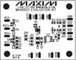
Figure 2. MAX6603 EV Kit Component Placement Guide—
Component Side
Figure 3. MAX6603 EV Kit PC Board Layout—Component Side
Figure 4. MAX6603 EV Kit PC Board Layout—Solder Side
Maxim cannot assume responsibility for use of any circuitry other than circuitry entirely embodied in a Maxim product. No circuit patent licenses are
implied. Maxim reserves the right to change the circuitry and specifications without notice at any time.
4 _____________________Maxim Integrated Products, 120 San Gabriel Drive, Sunnyvale, CA 94086 408-737-7600
© 2006 Maxim Integrated Products
Printed USA
is a registered trademark of Maxim Integrated Products, Inc.
�
很抱歉,暂时无法提供与“MAX6603EVKIT+”相匹配的价格&库存,您可以联系我们找货
免费人工找货