19-5083; Rev 0; 12/09
MAX97002 Evaluation Kit
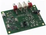
The MAX97002 evaluation kit (EV kit) is a fully assembled
and tested PCB that evaluates the MAX97002 mono
Class D audio power amplifier and stereo Class H
DirectDriveM headphone amplifier communicating over
a 2-wire I2C interface. The EV kit features an on-board
microcontroller for communicating with the I2C interface
of the MAX97002. Pads are provided for accessing the
analog inputs and amplifier outputs.
The MAX97002 EV kit requires a 2.7V to 5.5V supply for
PVDD and a 1.8V supply for VDD.
WindowsM 2000-, Windows XPM-, and Windows VistaMcompatible software is provided to facilitate configuration. The software controls an on-board microcontroller
over USB, which generates I2C commands.
Features
S Proven Audio PCB Layout
S On-Board USB Interface Circuit Generates
I2C-Compatible Signals
S PCB Pads for User-Supplied I2C-Compatible
Signals
S Surface-Mount Components
S Windows 2000-, Windows XP-, and Windows Vista
(32-Bit)-Compatible Software
S Fully Assembled and Tested
Ordering Information
PART
TYPE
MAX97002EVKIT+
EV Kit
+Denotes lead(Pb)-free and RoHS compliant.
Component List
DESIGNATION
C1, C3–C10,
C17
C2
C11, C12
QTY
QTY
DESCRIPTION
10
0.1FF Q10%, 16V X7R ceramic
capacitors (0603)
Murata GRM188R71C104K
DESCRIPTION
C26–C29,
C39–C42
0
Not installed, ceramic capacitors
(0402)
C31, C33
2
1
4.7FF Q10%, 6.3V X5R ceramic
capacitor (0603)
Murata GRM188R60J475K
0.1FF Q10%, 16V X7R ceramic
capacitors (0402)
Murata GRM155R71C104K
C43–C47
5
2
10pF Q5%, 50V C0G ceramic
capacitors (0603)
Murata GRM1885C1H100J
0.22FF Q10%, 10V X5R ceramic
capacitors (0402)
Murata GRM155R61A224K
D1
1
Green LED (0603)
GND
1
Black miniature test point
HPJK
1
3.5mm stereo phone jack, SMT
(3-position nonswitch)
C13, C15, C32,
C34
4
10FF Q10%, 6.3V X5R ceramic
capacitors (0603)
Murata GRM188R60J106M
C14, C16,
C22–C25,
C35–C38
10
1FF Q 10%, 10V X5R ceramic
capacitors (0402)
Murata GRM155R61A105K
C18, C19
2
C20
1
22pF Q5%, 50V C0G ceramic
capacitors (0603)
Murata GRM1885C1H220J
3300pF Q10%, 50V X7R ceramic
capacitor (0603)
Murata GRM188R71H332K
DESIGNATION
HPL
1
White miniature test point
HPR
1
Red miniature test point
JINA1, JINB1
2
White RCA jacks (left)
JINA2, JINB2
2
Red RCA jacks (right)
JU1, JU2
2
2-pin headers
L1, L2
0
Not installed, inductors
(provided with EV kit)
TOKO A916CY-220M
OUT-, OUT+
2
1-pin headers
DirectDrive is a registered trademark of Maxim Integrated
Products, Inc.
Windows, Windows XP, and Windows Vista are registered
trademarks of Microsoft Corp.
________________________________________________________________ Maxim Integrated Products 1
For pricing, delivery, and ordering information, please contact Maxim Direct at 1-888-629-4642,
or visit Maxim’s website at www.maxim-ic.com.
Evaluates: MAX97002
General Description
�Evaluates: MAX97002
MAX97002 Evaluation Kit
Component List (continued)
DESIGNATION
QTY
DESCRIPTION
DESIGNATION
P1
1
USB mini type-B receptacle
connector
R1, R10–R13,
R18, R19
7
0I Q5% resistors (0402)
R2
1
220I Q5% resistor (0603)
R3
1
10kI Q5% resistor (0603)
R4
1
2.2kI Q5% resistor (0603)
R5, R8, R9
3
1.5kI Q5% resistor (0603)
R6, R7
2
27I Q5% resistors (0603)
R14, R15
2
10I Q1% resistors (0402)
R16, R17
0
Not installed, resistors (0603)
R20, R21
2
0I Q5% resistors (0603)
R22, R23
2
22I Q5% resistors (0402)
TP1, TP2
0
Not installed, multipurpose test
points
1
Mono Class H speaker with
DirectDrive headphone amplifier
(20 WLP)
Maxim MAX97002EWP+
U1
U2
1
32-bit microcontroller
(68 QFN-EP*)
Maxim MAXQ2000-RAX+
QTY
DESCRIPTION
U3
1
93C46 type 3-wire EEPROM
(8 SO)
U4
1
UART-to-USB converter
(32 TQFP)
U5
1
3.3V regulator (5 SC70)
Maxim MAX8511EXK33+
(Top Mark: AEI)
U6
1
2.5V regulator (5 SC70)
Maxim MAX8511EXK25+
(Top Mark: ADV)
Y1
1
16MHz crystal (HCM49)
Hong Kong X'tals
SSM16000N1HK188F0-0
Y2
1
6MHz crystal (HCM49)
Hong Kong X'tals
SSL60000N1HK188F0-0
—
1
USB high-speed A-to-mini B
cable, 2m
—
2
Shunts
—
1
PCB: MAX97002 EVALUATION
KIT+
*EP = Exposed pad.
Component Suppliers
SUPPLIER
PHONE
WEBSITE
Hong Kong X’tals Ltd.
852-35112388
www.hongkongcrystal.com
Murata Electronics North America, Inc.
770-436-1300
www.murata-northamerica.com
TOKO America, Inc.
800-745-8656
www.tokoam.com
Note: Indicate that you are using the MAX97002 when contacting these component suppliers.
2 _______________________________________________________________________________________
�MAX97002 Evaluation Kit
FILE
DESCRIPTION
INSTALL.EXE
Verify that a shunt is installed on jumper JU3.
5)
Connect the USB cable from the PC to the EV kit
board. A New Hardware Found window pops up
when installing the USB driver for the first time.
If a window is not seen that is similar to the one
described above after 30s, remove the USB cable
from the board and reconnect it. Administrator privileges are required to install the USB device driver
on Windows.
6)
Follow the directions of the Found New Hardware
window to install the USB device driver. Manually
specify the location of the device driver to be
C:\Program Files\MAX97000_1_2 (default installation directory) using the Browse button. During
device driver installation, Windows may show a
warning message indicating that the device driver
Maxim uses does not contain a digital signature.
This is not an error condition and it is safe to proceed with installation. Refer to the USB_Driver_
Help.PDF document included with the software for
additional information.
7)
Connect the 5V power supply across the PVDD and
GND pads.
8)
Connect the 1.8V power supply across the VDD and
GND pads.
9)
Connect the speaker across the OUT+ and OUTtest points.
Installs the EV kit files on your
computer
MAX97000_1_2.EXE
Application program
FTD2XX.INF
USB device driver file
UNINST.INI
Uninstalls the EV kit software
USB_Driver_Help.PDF
4)
USB driver installation help file
Quick Start
Required Equipment
• 5V, 1A DC power supply (PVDD)
• 1.8V, 100mA DC power supply (VDD)
• Speaker
• Headphones
• User-supplied Windows 2000, Windows XP, or
Windows Vista PC with a spare USB port
• MAX97002 EV kit (cable included)
Note: In the following sections, software-related items
are identified by bolding. Text in bold refers to items
directly from the EV kit software. Text in bold and underlined refers to items from the Windows operating system.
Procedure
The MAX97002 EV kit is fully assembled and tested.
Follow the steps below to verify board operation:
10) Connect the headphones to HPJK.
1)
11) Enable the power supplies.
Visit www.maxim-ic.com/evkitsoftware to download the latest version of the EV kit software,
MAX97000_1_2xx.ZIP. Save the EV kit software to a
temporary folder and uncompress the ZIP file.
2)
Install the EV kit software on the computer by running the INSTALL.EXE program inside the temporary folder.
3)
Verify that shunts are installed on jumpers JU1 and
JU2. This configures the I2C inputs to receive signals from the USB interface circuitry.
12) Start the MAX97002 EV kit software by selecting its
icon in the Start | Programs menu.
13) Observe as the program automatically detects the
address of the MAX97002 and starts the main program.
14) The MAX97002 is now ready for evaluation.
_______________________________________________________________________________________ 3
Evaluates: MAX97002
MAX97002 EV Kit Files
�Evaluates: MAX97002
MAX97002 Evaluation Kit
Detailed Description of Software
Note: Text in bold refers to items in the EV kit software.
Graphical User Interface (GUI)
The MAX97002 EV kit software GUI (Figures 1 and
2) provides a convenient way to test the features of
the MAX97002. Figure 1 shows the MAX97002 EV kit
software’s Main Control tab, while Figure 2 shows the
Registers tab. Actions on the two tabs generate I2C
commands to update the MAX97002 internal memory
registers.
The MAX97002 EV kit software Main Control tab
(Figure 1) divides the EV kit functions into logical blocks.
The MAX97002 EV kit software Registers tab (Figure 2)
displays each register’s individual bit logic-level status.
A data bit in bold indicates a logic-high, while a nonbolded data bit indicates a logic-low. Clicking on the
individual data bit toggles the bit and performs a write
command. The new command is shown in the edit box
at the right. Write commands can be written to the registers alternatively by typing a hex value in the edit box
and pressing Enter on the keyboard.
Figure 1. MAX97002 Evaluation Kit Software (Main Control Tab)
4 _______________________________________________________________________________________
�MAX97002 Evaluation Kit
Evaluates: MAX97002
Figure 2. MAX97002 Evaluation Kit Software (Registers Tab)
_______________________________________________________________________________________ 5
�Evaluates: MAX97002
MAX97002 Evaluation Kit
Software Startup
Upon starting the program, the MAX97002 EV kit software
automatically searches for the USB interface circuit and
then for the MAX97002 device address. The MAX97002
EV kit enters the normal operating mode when the
USB connection is detected and has found the device
address. If the USB connection is not detected, the software prompts the user to retry or enter the demo mode.
(unchecked), the ZCD forces all volume adjustment to
be made when the output signal is crossing zero, thus
reducing audio clicks during volume changes.
Input Gain
The MAX97002 EV kit software’s Input Gain group box
selects the input channel preamp gain for the MAX97002.
The MAX97002 input channel preamp gain is selectable
among -6dB, -3dB, 0dB, +3dB, +6dB, +9dB, and +18dB.
Demo Mode
The MAX97002 EV kit software enters the demo mode
when the USB connection is not detected, or by selecting the Options | Demo Mode menu item in the main
window. When in demo mode, all software communication to the EV kit circuit is disabled; however, most of the
software GUI is functional. Demo mode allows the user
to evaluate the software without hardware connectivity.
If the USB cable is connected to the EV kit, but power
is not applied to PVDD, the EV kit GUI acts like it is in
demo mode. In such a case, the EV kit is connected to
the PC through USB and I2C commands can be sent to
the MAX97002, but without power, the MAX97002 does
not acknowledge the I2C commands. When power is
applied, press the Reset button to detect the presence
of the MAX97002.
Write All/Read All/Reset
The Write All button writes the current settings to all of
the registers on the GUI. The EV kit software GUI performs I2C write commands as changes occur on the GUI.
The Read All button changes the GUI settings to match
the MAX97002 register settings. To change settings one
time, enter demo mode by selecting the Options | Demo
Mode menu item, change the GUI to the required settings,
exit demo mode by selecting Options | Demo Mode, and
then press the Write All button. If further changes are not
required, enter demo mode to disable communication to
the MAX97002. To obtain the MAX97002 settings, exit
demo mode and press the Read All button. The Reset
button clears the EV kit software GUI and reprograms the
MAX97002 to default values.
MAX97002 Master Controls
The EV kit software’s MAX97002 Master Controls group
box contains ENABLE, Volume Slew Disable, and Zero
Crossing Detection Disable checkboxes. The ENABLE
checkbox, which is also called the software shutdown,
enables or disables the MAX97002. The Volume Slew
Disable checkbox, when checked, disables the volume
slewing. The Zero Crossing Detection Disable checkbox disables the zero-crossing detection (ZCD) during a
volume change operation when checked. When enabled
Charge Pump
The MAX97002 features an internal charge pump for
Maxim’s Class H DirectDrive architecture. The charge
pump can operate in two modes, fixed mode and highefficiency mode. By default, the MAX97002 charge pump
operates in high-efficiency mode. High-efficiency mode
on the charge pump dynamically changes the internal
supply rails. To have fixed internal supply rails, check the
Fixed Mode checkbox in the Charge Pump group box.
Within fixed mode, there are two options for the supply
rails shown in the drop-down list, ±1.8V and ±0.9V.
Distortion Limiter
The distortion limiter limits distortion based on the defined
THD level and has programmable release time.
Switch Enable
The MAX97002 features an internal switch that can bypass
the Class D amplifier and allow an external amplifier to
power the same speaker connected to the MAX97002 EV
kit without requiring external switches. Connect the external amplifier output to COM1 and COM2, and enable in
the software by checking the Switch Closed checkbox
in the Analog Switch group box.
Low-Power Mode
The MAX97002’s low-power mode minimizes current consumption when only using the headphone amplifier. Lowpower mode transmits a single-ended audio signal to the
headphone amplifier from either INA or INB, or a differential signal from INA and INB. Low-power mode can be
enabled by selecting LP Mode from the drop-down list.
The volume control and mixer are bypassed in this mode.
Mixer
The speaker, left headphone, and right headphone
each have an independent mixer. The MAX97002 EV kit
accepts a pair of single-ended audio inputs for stereo
operation, or a pair of differential audio inputs for mono
operation. The single-ended input signals for the speaker
and headphones are defined as IN_1 (left) and IN_2
(right). In the Input Configuration group box, select
Stereo (S/E) for single-ended stereo operation or Mono
6 _______________________________________________________________________________________
�MAX97002 Evaluation Kit
Speaker Amplifier
The MAX97002 EV kit software’s Speaker Amplifier
group box contains the speaker mixer, speaker volume,
and speaker-enable control. Check the Speaker Enable
checkbox to enable the speaker amplifier. The Speaker
Volume track bar sets the speaker volume between
-30dB (min) to +20dB (max). Alternatively, the user can
enter a numerical value inside the Speaker Volume edit
box.
Headphone Amplifier
The Headphone Amplifier group box enables or disables the headphone outputs. The Left Headphone
Volume and Right Headphone Volume track bars
set the headphone volume. The Left HP Enable and
Right HP Enable checkboxes enable the headphone
amplifiers.
volume, respectively, to between -64dB (min) to +6dB
(max). Alternatively, the user can enter a numerical
value inside the Left Headphone Volume and Right
Headphone Volume edit boxes.
I2C Interface Indicator
The MAX97002 EV kit software Interface group box displays the MAX97002’s I2C Device Address, Register
Address, and the last Data Sent. The MAX97002 I2C
device address is internally set to 0x9A.
Simple I2C Commands
There are three methods for communicating with
the MAX97002 EV kit, through the Main Control tab
(Figure 1), the Registers tab (Figure 2), or by using lowlevel SMBusK commands available in the Advanced
User Interface window (Figure 3). Select the Options
| Interface (Advanced User Interface) menu item to
display the Advanced User Interface window that
allows I2C operations, such as SMBusReadByte and
SMBusWriteByte.
The Left Headphone Volume and Right Headphone
Volume track bars set the left and right headphone
Figure 3. Advanced User Interface Window (2-Wire Interface Tab Sheet)
SMBus is a trademark of Intel Corp.
_______________________________________________________________________________________ 7
Evaluates: MAX97002
(DIF) for differential mono operation. Depending on the
selection, the speaker and headphone mixers provide
options for selecting the audio source for the SPKR
Mixer, Left HP Mixer, and Right HP Mixer.
�Evaluates: MAX97002
MAX97002 Evaluation Kit
Detailed Description of Hardware
The MAX97002 EV kit evaluates the MAX97002 Class D
audio amplifier and stereo DirectDrive headphone amplifier that communicate over I2C. The EV kit demonstrates
the MAX97002 features, such as user-defined input configuration, input gain, input source, output enable, and
volume control.
The MAX97002 EV kit uses the MAX97002 IC in a
20-bump WLP (2mm x 2mm) package on a proven fourlayer PCB design. The EV kit operates from a 2.7V to
5.5V supply for PVDD and a 1.8V supply for VDD.
Filterless Output
The MAX97002 EV kit filterless outputs (OUT+/OUT-)
can be connected directly to a speaker load without
any filtering. Use the OUT+/OUT- test points to connect
the speaker directly to the MAX97002 outputs using a
twisted-pair cable. Do not install inductors L1 and L2 for
maximum efficiency.
Filtered Output
Audio analyzers typically cannot accept pulse-widthmodulated (PWM) signals at their inputs. Therefore, the
MAX97002 EV kit includes a pair of lowpass filters at
the output to ease evaluation. To use the filtering output
pads (FOUT+/FOUT-), install inductors L1 and L2 (provided with the EV kit), connect the load between FOUT+
and FOUT-, and connect the filtered output to the audio
analyzer. The lowpass filters at the speaker outputs are
optimized for an 8I speaker.
Table 1. MAX97002 Jumper Table
JUMPER
SHUNT
POSITION
Closed*
JU1
Open
Closed*
JU2
Open
DESCRIPTION
On-board I2C (connects onboard SCL signal to the SCL
pad)
User-supplied I2C (open the
jumper and apply the SCL signal to the SCL pad)
On-board I2C (connects onboard SDA signal to the SDA
pad)
User-supplied I2C (open the
jumper and apply the SDA signal to the SDA pad)
*Default position.
8 _______________________________________________________________________________________
�MAX97002 Evaluation Kit
Evaluates: MAX97002
Figure 4a. MAX97002 EV Kit Schematic (Sheet 1 of 2)
_______________________________________________________________________________________ 9
�Evaluates: MAX97002
MAX97002 Evaluation Kit
Figure 4b. MAX97002 EV Kit Schematic (Sheet 2 of 2)
10
�������������������������������������������������������������������������������������
�MAX97002 Evaluation Kit
Figure 5. MAX97002 EV Kit Component Placement Guide—
Component Side
Figure 6. MAX97002 EV Kit PCB Layout—Component Side
1.0’’
Figure 7. MAX97002 EV Kit PCB Layout—GND Layer 2
______________________________________________________________________________________ 11
Evaluates: MAX97002
1.0’’
1.0’’
�Evaluates: MAX97002
MAX97002 Evaluation Kit
1.0’’
Figure 8. MAX97002 EV Kit PCB Layout—Power Layer 3
1.0’’
Figure 9. MAX97002 EV Kit PCB Layout—Solder Side
Maxim cannot assume responsibility for use of any circuitry other than circuitry entirely embodied in a Maxim product. No circuit patent licenses are implied.
Maxim reserves the right to change the circuitry and specifications without notice at any time.
12
© 2009
Maxim Integrated Products, 120 San Gabriel Drive, Sunnyvale, CA 94086 408-737-7600
Maxim Integrated Products
Maxim is a registered trademark of Maxim Integrated Products, Inc.
�