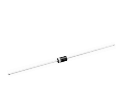
1N
4001A / RL101
THRU
1N
/ RL107
4007A
DC COMPONENTS CO., LTD.
R
RECTIFIER SPECIALISTS
TECHNICAL SPECIFICATIONS OF GENERAL PURPOSE SILICON RECTIFIER
VOLTAGE RANGE - 50 to 1000 Volts
CURRENT - 1.0 Ampere
FEATURES
*
*
*
*
*
Low cost
Low leakage
Low forward voltage drop
High current capability
High reliability
A-405
MECHANICAL DATA
*
*
*
*
*
*
Case: Molded plastic
Epoxy: UL 94V-0 rated flame retardant
Lead: MIL-STD-202E, Method 208 guaranteed
Polarity: Color band denotes cathode end
Mounting position: Any
Weight: 0.33 gram approx.
1.0(25.4)
MIN.
.025(0.65)
DIA.
.021(0.55)
.205(5.2)
.166(4.2)
.107(2.7)
DIA.
.080(2.0)
1.0(25.4)
MIN.
MAXIMUM RATINGS AND ELECTRICAL CHARACTERISTICS
o
Ratings at 25 C ambient temperature unless otherwise specified.
Single phase, half wave, 60Hz, resistive or inductive load.
For capacitive load, derate current by 20%.
Dimensions in inches and (millimeters)
1N4001A 1N4002A 1N4003A 1N4004A 1N4005A 1N4006A 1N4007A
SYMBOL RL101
RL102
RL103
RL104
RL105
RL106
RL107 UNITS
Maximum Recurrent Peak Reverse Voltage
VRRM
50
100
200
400
600
800
1000
Volts
Maximum RMS Voltage
VRMS
35
70
140
280
420
560
700
Volts
Maximum DC Blocking Voltage
VDC
50
100
200
400
600
800
1000
Volts
Maximum Average Forward Rectified Current
o
375"(9.5mm) lead length at T A = 55 C
IO
1.0
Amps
Peak Forward Surge Current 8.3 ms single half sine-wave
superimposed on rated load (JEDEC Method)
IFSM
30
Amps
Maximum Instantaneous Forward Voltage at 1.0A DC
VF
1.1
Volts
Maximum DC Reverse Current at Rated
DC Blocking Voltage
o
@ TA=25 C
5.0
o
@ TA=100 C
50
IR
Maximum Full Load Reverse Current Average, Full
o
Cycle .375”(9.5mm) lead length at TL = 55 C
Typical Junction Capacitance (Note 1)
Typical Thermal Resistance (Note 2)
Operating and Storage Temperature Range
µAmps
30
CJ
pF
15
RθJ A
50
TJ, T STG
-55 to +150
o
C/ W
o
C
Note 1: Measured at 1 MHz and applied reverse voltage of 4.0 volts.
Note 2: Typical thermal resistance from junction to ambient.
REV-3,MAY,2017
1
www.dccomponents.com
�1N4001A
1N4007A
RATING AND CHARACTERISTIC CURVES (
THRU
)
RL101
RL107
PEAK FORWARD SURGE CURRENT, (A)
AVERAGE FORWARD CURRENT, (A)
FIG. 1
TYPICAL FORWARD CURRENT
DERATING CURVE
1.0
.8
.6
.4
Single Phase
Half Wave 60Hz
Resistive or
Inductive Load
.2
0
0
25
50
75
100
125
150
FIG. 2
MAXIMUM NON-REPETITIVE FORWARD
SURGE CURRENT
50
8.3ms Single Half Sine-Wave
(JEDEC Method)
40
30
20
10
0
1
2
O
AMBIENT TEMPERATURE, ( C)
6
8 10
20
40
60 80 100
FIG. 4
TYPICAL REVERSE CHARACTERISTICS
FIG. 3
TYPICAL INSTANTANEOUS
FORWARD CHARACTERISTICS
1000
20
10
O
INSTANTANEOUS REVERSE CURRENT, (µA)
INSTANTANEOUS FORWARD CURRENT, (A)
4
NUMBER OF CYCLES AT 60Hz
3.0
1.0
O
TJ=25 C
Pulse Width=300µs
1% Duty Cycle
0.3
0.1
.03
.01
0.4
0.6
0.8
1.0
1.2
1.4
1.6
1.8
INSTANTANEOUS FORWARD VOLTAGE, (V)
TJ=125 C
100
O
TJ=100 C
10
1
O
TJ=25 C
.1
0
20
40
60
80
100
120
140
PERCENT OF RATED PEAK REVERSE VOLTAGE, (%)
FIG. 5
TYPICAL JUNCTION CAPACITANCE
JUNCTION CAPACITANCE, (pF)
200
100
60
40
20
10
O
TJ=25 C
6
4
2
1
.1
.2
.4
1.0
2
4
10
20
40
100
REVERSE VOLTAGE, (V)
REV-3,MAY,2017
2
www.dccomponents.com
�Disclaimer
Any Customer or user of this document or products described herein in such applications shall assume
all risks of such use and will agree to hold DC COMPONENTS are harmless against all damages.
DC COMPONENTS disclaims any and all liability arising out of the application or use of any product, including
consequential or incidental damages. Statement regarding the suitability of products for certain types
of applications are based on DC COMPONENTS ’s knowledge of typical requirements that are often placed
on DC COMPONENTS products in generic applications. Such statements are not binding statements about
the suitability of products for aparticular application. It is the customer's responsibility to validate that a
particular product with the properties described in the product specification is suitable for use in a particular
application.
DC COMPONENTS reserve the right to make modifications, enhancements, improvements, corrections
or other changes without further notice to this document and any product described herein, and disclaim
any and all liability for any errors, inaccuracies or incompleteness contained in any datasheet or in any
other disclosure relating to any product. Parameters provided in datasheets and specifications may
vary in different applications and performance may vary over time. All operating parameters, including
typical parameters, must be validated for each customer application by the customer’s technical experts.
Product specifications do not expand or otherwise modify DC COMPONENTS ’s terms and conditions
of purchase, including but not limited to the warranty expressed therein.
Unless otherwise in writing, DC COMPONENTS products are intended for use as general electronic components
in standard applications ( eg: Consumer electronic, Computer equipment, Office equipment, etc.), and not
recommended for use in a high specific application where a failure or malfunction of the device could result
in human injury or death ( eg: Aerospace equipment, Submarine cables, Combustion equipment, Safety
devices, Life support systems, etc.)
Customers using or selling DC COMPONENTS products not expressly indicated for use in such applications
do so at their own risk. If customer intended to use DC COMPONENTS standard quality grade devices for
applications not envisioned by DC COMPONENTS, please contact our sales representatives in advance.
DC COMPONENTS CO., LTD.
R
REV-3,MAY,2017
3
www.dccomponents.com
�
很抱歉,暂时无法提供与“1N4007A”相匹配的价格&库存,您可以联系我们找货
免费人工找货