TECHNICAL DATASHEET
CliQ II Buffer Module
24 V 20 A / DRB-24V020AB□
Highlights & Features
•
•
•
•
•
Minimum buffering time of 250 ms @ 24 V/20 A
Flexible operating buffering voltage modes:
Fixed mode at 22 Vdc
Dynamic mode for Vin -1V
Supports parallel connection to extend buffering time
Conformal coating on PCBAs to protect against common
dust and chemical pollutants
Hazardous Locations approval to ATEX and Class I, Div 2
(DRB-24V020ABA)
Safety Standards
CB Certified for worldwide use
Model Number:
DRB-24V020AB☐
Unit Weight:
0.76 kg (1.68 lb)
Dimensions (L x W x D): 121 x 70 x 120.1 mm
(4.76 x 2.76 x 4.73 inch)
General Description
Delta’s CliQ II buffer module offers the most widely used output voltage of 24 V and one of the longest minimum buffering time of
250ms at 20A in wide input range from 22.8 Vdc to 28.8 Vdc. The buffer module utilizes maintenance-free electrolytic capacitors to
store energy, thus eliminates the need of periodic replacement as compared to costlier batteries which also have shorter functional life
span. The DRB-24V020AB☐ comes with comprehensive protection features like overvoltage, over current and short circuit protections.
The rugged compact aluminium case is shock and vibration resistant according to IEC 60068-2 standard.
Model Information
CliQ II Buffer Module
Model Number
Input Voltage Range
Rated Output Voltage
Rated Output Current
DRB-24V020AB☐
22.8-28.8 Vdc
24 Vdc typ. (Depends on Vin)
20.0 A
Model Numbering
DR
B–
24V
020A
B
□
DIN Rail
Buffer Module
Output Voltage
Output Current
CliQ II Series
A - Metal Case,
with Class I, Div
N - Metal Case,
without Class I, Div 2
1
All parameters are specified at 25°C ambient and AC input unless otherwise indicated.
www.DeltaPSU.com (November 2021, Rev. 06)
�TECHNICAL DATASHEET
CliQ II Buffer Module
24 V 20 A / DRB-24V020AB□
Specifications
Input Ratings / Characteristics
Nominal Input Voltage
24 Vdc
Input Voltage Range
22.8-28.8 Vdc
Maximum Input Voltage
Input Current
35 Vdc
Charging Mode
Discharging Mode
Max Power Dissipation
Standby Mode
< 0.6 A
20 A Max
2.5 W Average
Maximum Signal Input (Inhibit)
35 V / 10 mA
Max Inrush Current (Cold Start)
< 20 A
Charging Time
< 30 s
Output Ratings / Characteristics
Nominal Output Voltage Range
24 Vdc typ. (Depends on Vin)
Output Voltage Adjustment Range
22-28 Vdc
Switch = “Fix 22 V”
(Factory Setting)
Switch = “Vin-1 V”
Buffering starts if terminal voltage falls below 22 V
Buffering starts if terminal voltage is decreased by > 1 V
Maximum Output Voltage
35 Vdc
Output Current
20 A Max
Output Power
480 W Max (24 V/20 A)
Buffering Time
250 ms Min @ 24 V/20 A Load,
5 s Min @ 24 V/1 A Load (Refer to Fig. 1)
Maximum Signal Output
35 V / 10 mA
Signals
Inhibit Signal (I)
(Low: < 1V; High: > +VS-2V)
“Low” = Shuts down buffer module
Ready Signal (R)
“High” = Buffer module is fully charged or in standby mode
Buffering Signal (B)
“High” = Buffer module is discharging or in buffering mode
Supply Voltage (+VS)
Common +VS (35 V Max)
PARD (20 MHz)
< 200 mVpp @ 25°C, buffering mode
Parallel Connection
Yes
Series Connection
No
Protective Device
Transient Voltage Suppressor (TVS) for signals
Fig. 1
2
Buffering Time (Typical Values at “Vin-1 V”)
All parameters are specified at 25°C ambient and AC input unless otherwise indicated.
www.DeltaPSU.com (November 2021, Rev. 06)
�TECHNICAL DATASHEET
CliQ II Buffer Module
24 V 20 A / DRB-24V020AB□
Mechanical
Case Cover / Chassis
Aluminium
Dimensions (L x W x D)
121 x 70 x 120.1 mm (4.76 x 2.76 x 4.73 inch)
Unit Weight
0.76 kg (1.68 lb)
LED Indicators
Green LED Off
Unit is discharged or Vin < 22 Vdc
Green LED On
Unit is fully charged
Green LED Flashing
Slowly (1Hz)
Unit is charging
Green LED Flashing
Quickly (10Hz)
Unit is discharging
Cooling System
Terminal
Wire
Convection
Input / Output
2 Pins (Rated 300 V/30 A)
Signal
5 Pins (Rated 300 V/30 A)
Input / Output
AWG 12-10
Signal
AWG 24-10
Mounting Rail
Standard TS35 DIN Rail in accordance with EN 60715
Noise (1 Meter from power supply)
Sound Pressure Level (SPL) < 40 dBA
Environment
Surrounding Air Temperature
Power De-rating
Operating
-25°C to +75°C
Storage
-25°C to +85°C
Vertical Mounting
> 70°C de-rate power by 5% / °C
Horizontal Mounting
> 70°C de-rate power by 5% / °C
Operating Humidity
5 to 95% RH (Non-Condensing)
Operating Altitude
0 to 2,500 Meters (8,200 ft.)
Shock Test
Non-Operating
IEC 60068-2-27, 30 G (300 m/S²) for a duration of 18 ms,
1 time per direction, 2 times in total
Vibration
Non-Operating
IEC 60068-2-6, 10 Hz to 500 Hz @ 30 m/S² (3G peak);
60 min per axis for all X, Y, Z direction
Pollution Degree
2
Protections
Overvoltage
32 V ± 10%
Overload / Overcurrent
30 A Max
Short Circuit
No Damage
Penetration Protection
> 3.5 mm (e.g. screws, small parts)
Reverse Polarity Protection
Yes
Degree of Protection
IP20
Protection Against Shock
Class I with PE* connection
*PE: Primary Earth
3
All parameters are specified at 25°C ambient and AC input unless otherwise indicated.
www.DeltaPSU.com (November 2021, Rev. 06)
�TECHNICAL DATASHEET
CliQ II Buffer Module
24 V 20 A / DRB-24V020AB□
Reliability Data
MTBF (at Vin-1V Mode)
> 800,000 hrs. as per Telcordia SR-332 @ Standby Mode
(Buffer module in Ready State)
Expected Cap Life Time
10 years (Standby Mode @ 40°C)
Safety Standards / Directives
Electrical Equipment of Machines
EN/BS EN 60204-1
Electrical Equipment for Use in Electrical Power Installations
IEC/EN/BS EN 62477-1 / IEC 62103
Electrical Safety
EN 62368-1
SIQ Bauart
UL/cUL recognized
CB scheme
UKCA
Industrial Control Equipment
UL/cUL listed
CSA
Hazardous Location / ATEX
(For DRB-24V020ABA)
UL 60950-1 and CSA C22.2 No. 60950-1 (File No. E191395)
UL 62368-1 and CSA C22.2 No. 62368-1 (File No. E191395)
IEC 60950-1, IEC 62368-1
BS EN 62368-1
UL 508 and CSA C22.2 No. 107.1-01 (File No. E315355)
CSA C22.2 No. 107.1-01 (File No. 181564)
cCSAus
CSA C22.2 No. 213-M1987, ANSI / ISA 12.12.01:2007
[Class I, Division 2, Group A, B, C, D T4, Ta= -25°C to +75°C
(> +70°C derating)]
ATEX
EN 60079-0:2009, EN 60079-15:2010 [
II 3G Ex nA IIC T4
Gc, Ta= -25°C to +75°C (> +70°C derating)]
CE
Certificate No. EPS 12 ATEX 1 491 X
In conformance with EMC Directive 2014/30/EU and
Low Voltage Directive 2014/35/EU
UKCA
For DRB-24V020ABA:
In conformance with Equipment for explosive atmospheres
(ATEX) directive 2014/34/EU
In conformance with Electrical Equipment (Safety)
Regulations 2016 No. 1011 and
The Electromagnetic Compatibility Regulations 2016 No. 1091
1.5 KVac
Galvanic Isolation
Input & Output / PE
Signal / PE
4
1.5 KVac
All parameters are specified at 25°C ambient and AC input unless otherwise indicated.
www.DeltaPSU.com (November 2021, Rev. 06)
�TECHNICAL DATASHEET
CliQ II Buffer Module
24 V 20 A / DRB-24V020AB□
EMC
Emissions (CE & RE)
Generic Standards: CISPR 32, EN/BS EN 55032,
EN/BS EN 55011, FCC Title 47: Class B
Component Power Supply for General Use
EN 61204-3
Immunity
Generic Standards: EN/BS EN 55024, EN/BS EN 61000-6-2
Electrostatic Discharge
IEC 61000-4-2
Level 4 Criteria A1)
Air Discharge: 15 kV
Contact Discharge: 8 kV
Radiated Field
IEC 61000-4-3
Level 3 Criteria A1)
80 MHz-1 GHz, 10 V/M, 80% modulation (1 KHz)
Electrical Fast Transient / Burst
IEC 61000-4-4
Level 3 Criteria A1)
2 kV
Surge
IEC 61000-4-5
Level 3 Criteria A1)
Common Mode2): 2 kV
Differential Mode3): 1 kV
Conducted
IEC 61000-4-6
Level 3 Criteria A1)
150 kHz-80 MHz, 10 Vrms
Power Frequency Magnetic Fields
IEC 61000-4-8
Criteria A1)
10 A/Meter
Voltage Dips and Interruptions
IEC 61000-4-11
Level 3 Criteria A 1)
Additional 100% dip; 1 cycle (20 ms); No Damage
Low Energy Pulse Test (Ring Wave)
IEC 61000-4-12
Level 3 Criteria A1)
Common Mode2): 2 kV
Differential Mode3): 1 kV
Harmonic Current Emission
IEC/EN/BS EN 61000-3-2, Class A
Voltage Fluctuation and Flicker
IEC/EN/BS EN 61000-3-3
Note: Product intended to be used as Apparatus with AC-DC Power Supply, EMC compliance to be verified in correspondence to the connected units.
1) Criteria A: Normal performance within the specification limits
2) Asymmetrical: Common (Line to earth)
3) Symmetrical: Differential mode (Line to line)
5
All parameters are specified at 25°C ambient and AC input unless otherwise indicated.
www.DeltaPSU.com (November 2021, Rev. 06)
�TECHNICAL DATASHEET
CliQ II Buffer Module
24 V 20 A / DRB-24V020AB□
Block Diagram
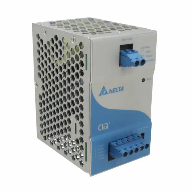
Device Description
1)
2)
3)
4)
5)
6
Input / Output terminal block connector
Signal terminal block connector
Select switch (operation mode)
LED display status
Universal mounting rail system
All parameters are specified at 25°C ambient and AC input unless otherwise indicated.
www.DeltaPSU.com (November 2021, Rev. 06)
�TECHNICAL DATASHEET
CliQ II Buffer Module
24 V 20 A / DRB-24V020AB□
Dimensions
L x W x D: 121 x 70 x 120.1 mm (4.76 x 2.76 x 4.73 inch)
Engineering Data
Output Load De-rating VS Surrounding Air Temperature
Note
1.
2.
3.
4.
Fig. 2
7
The unit may degrade, or be damaged, when
it is continuously used outside the shaded
region, refer to the graph shown in Fig. 2.
In order for the device to function in the
manner intended, it is also necessary to keep
a safety distance as recommended in the
safety instructions while the device is in
operation.
Depending
on
the
surrounding
air
temperature and output load delivered by the
power supply, the device can be very hot!
If the device has to be mounted in any other
orientation, please contact info@deltapsu.com
for more details.
De-rating for Vertical and Horizontal Mounting Orientation
> 70°C de-rate power by 5% / °C
All parameters are specified at 25°C ambient and AC input unless otherwise indicated.
www.DeltaPSU.com (November 2021, Rev. 06)
�TECHNICAL DATASHEET
CliQ II Buffer Module
24 V 20 A / DRB-24V020AB□
Assembly & Installation
The unit can be mounted on 35 mm DIN rails in accordance with EN 60715. The device should be installed with Input / Output terminal
block at the top.
Each device is delivered ready to install.
Mounting
Dismounting
Fig. 3.1 Mounting
Fig. 3.2 Dismounting
Snap on the DIN rail as shown in Fig. 3.1:
1. Tilt the unit upwards and insert it onto the DIN rail.
2. Push downwards until stopped.
3. Press against the bottom front side for locking.
4. Shake the unit slightly to ensure that it is secured.
To uninstall, pull or slide down the latch with screw driver as
shown in Fig. 3.2. Then slide the unit in the opposite direction,
release the latch and pull out the unit from the rail.
In accordance to EN 60950 / UL 60950 and EN 62368 / UL 62368, flexible cables require ferrules.
Use appropriate copper cables designed to sustain operating temperature of:
1. 60°C, 60°C / 75°C for USA
2. At least 90°C for Canada.
8
All parameters are specified at 25°C ambient and AC input unless otherwise indicated.
www.DeltaPSU.com (November 2021, Rev. 06)
�TECHNICAL DATASHEET
CliQ II Buffer Module
24 V 20 A / DRB-24V020AB□
Safety Instructions
Horizontal Mounting
Vertical Mounting
•
ALWAYS switch mains of input power OFF before connecting and disconnecting the input voltage to the unit. If mains are not
turned OFF, there is risk of explosion / severe damage.
To guarantee sufficient convection cooling, please refer to the following instructions to ensure sufficient clearance
around the device.
Vertical Mounting: 50 mm (1.97 inch) above and below the device as well as a lateral distance of 20 mm (0.79 inch) to
other units.
Horizontal Mounting: 50 mm (1.97 inch) above and below the device as well as a lateral distance of 50 mm (1.97 inch) to
other units.
Note that the enclosure of the device can become very hot depending on the surrounding air temperature and load of the power
supply. Risk of burns!
The main power must be turned off before connecting or disconnecting wires to the terminals!
DO NOT insert any objects into the unit.
Hazardous voltages may be present for up to 5 minutes after the input mains voltage is disconnected. Do not touch the unit during
this time.
The unit is a built-in unit and must be installed in a cabinet or room (condensation free environment and indoor location) that is
relatively free of conductive contaminants.
•
•
•
•
•
•
For DRB-24V020ABA:
•
The unit must be installed in an IP54 enclosure or cabinet in the final installation. The enclosure or cabinet must comply with EN
60079-0 or EN 60079-15.
•
Warning: Explosion Hazard - Substitution of components may impair suitability for Class I, Division 2.
•
Warning: Explosion Hazard - Do not disconnect equipment or adjust switch unless the power has been switched off or the area is
known to be non-hazardous.
9
All parameters are specified at 25°C ambient and AC input unless otherwise indicated.
www.DeltaPSU.com (November 2021, Rev. 06)
�TECHNICAL DATASHEET
CliQ II Buffer Module
24 V 20 A / DRB-24V020AB□
Functions
Buffering, Ready and Inhibit Signal Characteristics
Signal Level
Low: < 1 V; High: < +VS-2 V
Supply Voltage (+VS)
Min = 10 Vdc, Max = 35 Vdc
Maximum Signal Output
35 V / 10 mA
Buffering Signal (B)
“High” = Buffer module is discharging or in buffering mode
Isolation (Signal Port to Power Port)
1.5 KVac
LED Indicator
Green LED Flashing Quickly (10Hz)
Ready Signal (R)
“High” = Buffer module is fully charged or in standby mode
Isolation (Signal Port to Power Port)
1.5 KVac
LED Indicator
Green LED On
Inhibit Signal (I)
“Low” = Shuts down buffer module
Shut-down Threshold
6 Vdc Min / 10 Vdc Max
Isolation (Signal Port to Power Port)
1.5 KVac
Operating Diagram
Wiring Schematics
Typical Application Notes can be found on
Page 9.
10
All parameters are specified at 25°C ambient and AC input unless otherwise indicated.
www.DeltaPSU.com (November 2021, Rev. 06)
�TECHNICAL DATASHEET
CliQ II Buffer Module
24 V 20 A / DRB-24V020AB□
Typical Application Notes
Fig. 4.1 General connection / wiring diagram
Fig. 4.2 Paralleling of buffer units
Fig. 4.3 Decoupling of buffered branches
Fig. 4.4 General signals wiring
Fig. 4.5 Signals supplied from an external voltage
Fig. 4.6 Connection diagram with redundant operation
11
All parameters are specified at 25°C ambient and AC input unless otherwise indicated.
www.DeltaPSU.com (November 2021, Rev. 06)
�TECHNICAL DATASHEET
CliQ II Buffer Module
24V 20A / DRB-24V020AB□
Connectable Power Supplies
The buffer module is recommended to be connected with the following power supplies:
CliQ Series
DRP024V060W1AA
DRP024V060W1AZ
DRP024V120W1AA
DRP024V240W1AA
DRP024V480W1AA
CliQ II Series
DRP024V060W1B☐
DRP024V120W1B☐
DRP024V240W1B☐
DRP024V480W1B☐
Inrush Current
Overvoltage Protection (Latch Mode)
Inrush current is the peak, instantaneous, input current measured
and, occurs when the input voltage is first applied. For DC input
voltages, the maximum peak value of inrush current will occur
during the first applied DC voltage.
The buffer module’s overvoltage protection will be activated when
DC input to the module exceeds the maximum specified input
voltage. The overvoltage limits are same as power supply limits,
32V±10%. Buffer module will shut down and latch during
overvoltage mode, and will return to normal operation upon
removal of fault and power supply input is recycled (ON/OFF) or
input to buffer module is recycled.
Short Circuit Protection (Latch Mode)
Overload & Overcurrent Protections (Latch Mode)
When the output current exceeds 120% of IO (Max load) buffer
module will shut down and latch. Normal operation of buffer
module can be resumed upon removal of fault and power supply
input is recycled (ON/OFF) or input to buffer module is recycled.
12
Buffer module is protected by short circuit during buffering mode,
in the event of short circuit the module will shut down and latch.
Operation can be resumed upon removal of fault and power
supply in put is recycled (ON/OFF) or input to buffer module is
recycled.
All parameters are specified at 25°C ambient and AC input unless otherwise indicated.
www.DeltaPSU.com (November 2021, Rev. 06)
�TECHNICAL DATASHEET
CliQ II Buffer Module
24V 20A / DRB-24V020AB□
Others
Conformal Coating
The Protective Coating Technology
Delta Electronics Group has designed the perfect dipping technique which penetrates everywhere including
under device, and prevents leakage. The conformal coating dipping can be applied to PCBAs or circuit board.
The coating preserves the performance of precision electronic primarily by preventing ionizable contaminants
such as salt from reaching circuit nodes, where the material slumps around sharp edges. This can be a problem
especially in highly conversing atmosphere.
Attention
Delta provides all information in the datasheets on an “AS IS” basis and does not offer any kind of warranty through the information for
using the product. In the event of any discrepancy between the information in the catalog and datasheets, the datasheets shall prevail
(please refer to www.DeltaPSU.com for the latest datasheets information). Delta shall have no liability of indemnification for any claim
or action arising from any error for the provided information in the datasheets. Customer shall take its responsibility for evaluation of
using the product before placing an order with Delta.
Delta reserves the right to make changes to the information described in the datasheets without notice.
Manufacturer and Authorized Representatives Information
Manufacturer
Thailand
Delta Electronics (Thailand) PCL.
909 Pattana 1 Rd., Muang, Samutprakarn, 10280 Thailand
Taiwan
Delta Electronics, Inc.
3 Tungyuan Road, Chungli Industrial Zone, Taoyuan County
32063, Taiwan
Authorized Representatives
The Netherlands
Delta Greentech (Netherlands) B.V.
Zandsteen 15, 2132 MZ Hoofddorp, The Netherlands
13
United Kingdom
Delta Electronics Europe Limited
1 Redwood Court, Peel Park Campus,
East Kilbride, Glasgow, G74 5PF, United Kingdom
All parameters are specified at 25°C ambient and AC input unless otherwise indicated.
www.DeltaPSU.com (November 2021, Rev. 06)
�