$XWRPDWLRQ�IRU�D�&KDQJLQJ�:RUOG
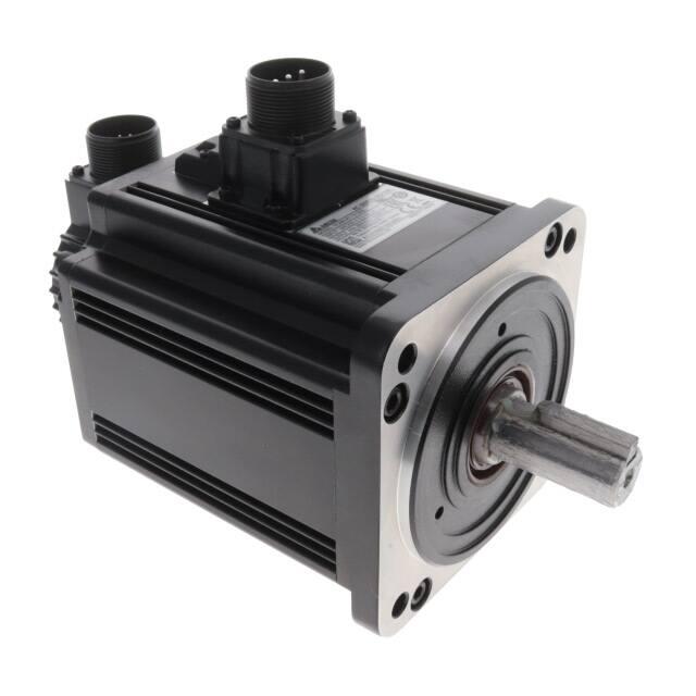
Delta AC Servo Drive & Motor
ASDA-A2 Series
�More Rapid, More Stable, More Precise
Delta Electronics, Inc., a leading manufacturer of industrial automation products, is pleased to
announce the launch of its new high-performance ASDA-A2 series servo motors and servo drives with
motion control.
The current trend for motion control has the control command source close to the drive. In response,
Delta has developed the new ASDA-A2 series that of fers excellent motion control so that the external
controller is almost eliminated. ASDA-A2 series features a built-in electronic cam (E-CAM) function which
provides an excellent solution for flying shear , rotary cut and synchronized motion applications. The all
QHZ�SRVLWLRQ�UHJLVWHU�FRQWURO�35�PRGH�LV�D�XQLTXH�DQG�VLJQL¿FDQW�IXQFWLRQ�WKDW�SURYLGHV�D�YDULHW\�RI�FRQWURO�
modes to enhance system performance.
The ASDA-A2 series also supports various industrial communications protocols, such as CANopen,
DMCNET, EtherCAT which of fers higher performance and high speed communications and enable the
drive to integrate with other part of the automation more ef ficiently and ef fectively. The full-closed loop
control, auto notch filter, vibration suppression and gantry control functions help to perform complex
motions that require high precision and smooth operation. The 20-bit superior resolution encoder which
is essential for accurate positioning applications is equipped as standard. In addition, the outstanding
Capture and Compare functions for high-speed pulses offer the best support for stepless positioning. Other
additional functionality, such as up to 1kHz frequency response, innovative editing software, high-speed
PC monitoring (similar to a digital oscilloscope), and more, all drastically maximize the performance of the
ASDA-A2 series.
Delta's new ASDA-A2 series is the ultimate servo system providing a total solution
for a wide range of machine tools and industrial applications
1
�Table of Contents
2
3
ASDA-A2 Series Features
9
Product Line-up
13
Model Explanation
14
Servo Motor Features
15
6HUYR�0RWRU�6SHFL¿FDWLRQV�����������������������������������
21
Servo Motor Dimensions
29
Part Names and Functions
31
Wiring
39
$6'$�6RIW�&RQ¿JXUDWLRQ�6RIWZDUH�
41
Optional Accessories
43
6HUYR�'ULYH�6SHFL¿FDWLRQV�
45
Servo Drive Dimensions
51
Optional Cables and Connectors
61
Servo Drive, Servo Motor and
Accessories Combinations
69
Safety Information
70
5HJHQHUDWLYH�5HVLVWRU�6SHFL¿FDWLRQV
�ASDA-A2 Series Features
DT3
High Positioning Accuracy
Ź
Ź
ECMA series servo motors feature incremental encoders with 20-bit resolution which can eliminate
unstable commands at low speed, smooth motor operation and enhance the accuracy of positioning.
Absolute encoder supported. 17-bit motor position will not get lost when power is cut off.
20-bit, incremental encoder /
17-bit, absolute encoder
ˊ
High Responsiveness
Ź
Up to 1kHz frequency response.
Ź
Settling time below 1ms.
Ź
7ms acceleration time for speeds from -3000 r/min to 3000 r/min with an empty load!
�1RWH��7KH�WHVW�UHFRUG�RI�D����:�PRWRU�ZLWK���PP�IUDPH�VL]H�
����
!"
��� �$��� ����
����
��#���
��������
�����������
�����������
��
�
�
�
�
���������
����
�
�
����
��������
��
��
���
����
����
���
����
�
�����
� ���
�����
�����
���
��
�
��
�
��
��
��
����
��
��
�����
� �
��
�
��
��
��
����
3
��
��
�
�Excellent Suppression Functions
Without Suppression
With Suppression
Function When Settling
Function When Settling
Resonance Suppression
(High Frequency)
7ZR�DXWR�QRWFK�¿OWHUV�DQG�
RQH�PDQXDO�QRWFK�¿OWHU�
are provided to suppress
mechanical resonance
HI¿FLHQWO\�
Notch Filter Starts
30
20
torque (Amp)
Ź
Vibration Suppression (Low Frequency)
7ZR�YLEUDWLRQ�VXSSUHVVLRQ�¿OWHUV�DUH�SURYLGHG�IRU�ORQJ�DUP�V\VWHP�WR�PLQLPL]H�WKH�YLEUDWLRQ�DW�
machine edges effectively.
10
0
-10
-20
-30
0
1
2
3
4
Before Suppression
5
6
7
t (sec)
7
t (sec)
After Suppression
2000
1500
Speed (rpm)
Ź
1000
500
0
-500
-1000
-1500
-2000
0
1
2
4
3
4
5
6
�ASDA-A2 Series Features
Full-Closed Loop Control Function
Ź
5HGXFHV�WKH�HIIHFWV�RI�EDFNODVK�DQG�ÀH[LELOLW\�IURP�WKH�PDFKLQH�DQG�
ensures the accuracy of positioning.
���
Ḣ䷏䢣♏
Motor Encoder
���
Linear Scale
ℰ⭟Ⱑ
Electronic CAM (E-CAM) Function
Ź
720 points max. for E-CAM outline.
Ź
6PRRWK�LQWHUSRODWLRQ�EHWZHHQ�SRLQWV�FDQ�EH�FRPSOHWHG�DXWRPDWLFDOO\�WR�\LHOG�D�ÀH[LEOH�SURJUDPPLQJ�
Ź
$6'$�6RIW�FRQ¿JXUDWLRQ�VRIWZDUH�VXSSRUWHG�
Ź
(DV\�WR�XVH�IRU�À\LQJ�VKHDU��URWDU\�FXW��DQG�RWKHU�FDP�DSSOLFDWLRQV�
�
ASDA-A2 E-CAM ⊆僤㖣
⋬壄㩆ᷱ䙫ㆰ䔏
�
E-CAM function of ASDA-A2 series
for packaging machines
� and
packaging lines
5
�Versatile PR Mode
Ź
$6'$�6RIW�FRQ¿JXUDWLRQ�VRIWZDUH�VXSSRUWHG�
Ź
New sub-modes supported, not traditional point-to-point control.
Ź
64 procedures can be applied.
Ź
0RWLRQ�SUR¿OH�FDQ�EH�FKDQJHG�LQVWDQWDQHRXVO\��
Ź
35 Homing modes / Jump mode / Write parameter mode /
Constant speed mode / Position control mode supported.
�����
�����
Overlap Command
Sequential Command
P_Command 1
P_Command 2
����
�
P_Command 1
�
��
����
A command is executed only when the
previous command is completed.
�����
The second command is executed after the
delay time or during the deceleration period.
Insertion Command
P_Command 2
P_Command 1
External command triggered
P_Command 2
����
Insertion changes the command executed at the
moment it is inserted.
6
�ASDA-A2 Series Features
Capture and Compare Functions
Capture - Position Latch Function
Ź
Latches the coordinate value on the
reference axis.
Ź
Response time is less than 5us.
Ź
It can be used to do mark tracing.
Ź
Maximum 800 records
���
Data Array
Linear
Encoder
Pulse
Train
������
������
Motor Encoder
When DI7 is triggered, the latched position is
recorded in Data Array.
Compare - Position Detection
Function
Ź
Ź
Ź
Ź
Detects the location on the
reference axis.
Response time is less than 5us.
Data Array
Linear
Encoder
Pulse
Train
Position
383838
It can be used for CCD camera
applications.
Motor Encoder
Position ==
383838
Maximum 800 records
True
ġ
DO4
When the record in Data Array is the same as the
detected position, DO4 will output.
7
�Supports High-Speed DMCNET, EtherCAT, CANopen Protocols for
Multi-Axis Synchronous Control
DOP-B
DVS
Ethernet
PCI-DMC
AH500
CANopen
DMCNET
MH1-S30D
or
ASDA-A2-F
ASDA-A2-E
Integrated Gantry Control
Axis 1
Sent From Host Controller
Pulse Command
Axis 2
Position Monitoring
8
DVP-10MC
ASDA-A2-M
�Product Line-up
220V Series
Servo Motors
Motor Series
Low Inertia
Medium Inertia
Medium-High Inertia
High Inertia
NOTE
Phase
ECMA-C 3000 r/min
ECMA-E 2000 r/min
ECMA-F 1500 r/min
ECMA-C/G 3000 r/min
1-phase / 3-phase
1-phase / 3-phase
1-phase / 3-phase
1-phase / 3-phase
Rated Output
Power (W)
Model Name
50
ECMA-C1040F
100
ECMA-C
0401
S
200
ECMA-C
0602
S
400
ECMA-C
0604
S
400
ECMA-C
0804
7
750
ECMA-C
0807
S
750
ECMA-C
0907
S
1000
ECMA-C
0910
S
1000
ECMA-C
1010
S
2000
ECMA-C
1020
S
3000
ECMA-C
1330
4
500
ECMA-E
1305
S
1000
ECMA-E
1310
S
1500
ECMA-E
1315
S
2000
ECMA-E
1320
S
2000
ECMA-E
1820
S
3000
ECMA-E
1830
S
3500
ECMA-E
1835
S
500
ECMA-F
1305
S
850
ECMA-F
1308
S
1300
ECMA-F
1313
S
1800
ECMA-F
1318
S
3000
ECMA-F
1830
S
4500
ECMA-F
1845
S
5500
ECMA-F
1855
3
7500
ECMA-F
1875
3
11000
ECMA-F1221B
3
15000
ECMA-F1221F
S
S
400
ECMA-C
0604
H
750
ECMA-C
0807
H
300
ECMA-G
1303
S
600
ECMA-G
1306
S
900
ECMA-G
1309
S
1) The boxes (
2) The boxes (
��DW�WKH�HQGV�RI�WKH�VHUYR�GULYH�PRGHO�QDPHV�DUH�IRU�RSWLRQDO�FRQ¿JXUDWLRQV��)RU�WKH�DFWXDO�PRGHO�QDPH��SOHDVH�UHIHU�WR�WKH�PRGHO�H[SODQDWLRQ�RI�W
) in the model names represent encoder type.
=1: Incremental encoder, 20-bit;
=2: Incremental encoder, 17-bit;
=A: Absolute type
3) The boxes (
) in the model names represent shaft end/brake or the number of oil seal.
9
�Servo Drives
Rated current (Arms)
Maximum current (A)
0.69 2.05
Model Name
Continuous Output
Current (Arms)
ASD-A2-0121-
0.90 2.70
ASD-A2-0221-
1.55 4.65
ASD-A2-0421-
2.60 7.80
ASD-A2-0721-
5.10 15.30
ASD-A2-1021-
7.30 21.90
ASD-A2-2023-
13.40 40.20
ASD-A2-3023-
19.40 58.20
2.90 8.70
ASD-A2-0421-
2.60 7.80
5.60 16.80
ASD-A2-1021-
7.30 21.90
8.30 24.90
ASD-A2-1521-
8.30 24.90
ASD-A2-2023-
13.40 40.20
ASD-A2-3023-
19.40 58.20
3.90 12.10
ASD-A2-0721-
5.10 15.30
7.10 19.40
ASD-A2-1021-
7.30 21.90
ASD-A2-2023-
13.40 40.20
19.40 58.20
ASD-A2-3023-
19.40 58.20
32.50 81.30
ASD-A2-4523-
32.50 70.7
40.00 100.00
ASD-A2-5523-
40.00 106
ASD-A2-7523-
47.50 141.1
ASD-A2-1B23-
54.40 141.1
67 162
ASD-A2-1F23-
70.00 212.2
2.60 7.80
ASD-A2-0421
2.60 7.80
5.10 15.30
ASD-A2-0721-
5.10 15.30
2.50 7.50
ASD-A2-0421-
2.60 7.80
4.80 14.40
ASD-A2-0721-
5.10 15.30
7.50 22.50
ASD-A2-1021-
7.30 21.90
0.90 2.70
1.55 4.65
2.60 7.80
2.60 7.80
5.10 15.30
3.66 1
1.00
4.25 12.37
7.30 21.90
12.05 36.15
17.2
47.5
11.01 33.03
11.22 33.66
16.10 48.30
19.20 57.60
12.60 38.60
13.00 36.00
47.50 1
51.80 129.50
18.80
WKH�VHUYR�GULYH�
10
Max. Instantaneous
Current (A)
�Product Line-up
400V Series
Servo Motors
Motor Series
Low Inertia
Medium Inertia
Medium-High Inertia
High Inertia
NOTE
Phase
ECMA-J 3000 r/min
3-phase
ECMA-K 2000 r/min
3-phase
ECMA-L 1500 r/min
3-phase
ECMA-G 3000 r/min
1) The boxes (
3-phase
Rated Output
Power (W)
Model Name
400
ECMA-J
0604
S
750
ECMA-J
0807
S
750
ECMA-J
0907
S
1000
ECMA-J
0910
S
1000
ECMA-J
1010
S
2000
ECMA-J
1020
S
3000
ECMA-J
1330
4
750
ECMA-K
1305
S
1000
ECMA-K
1310
S
1500
ECMA-K
1315
S
2000
ECMA-K
1320
S
2000
ECMA-K
1820
S
750
ECMA-L
1305
S
850
ECMA-L
1308
S
1300
ECMA-L
1313
S
3000
ECMA-L
1830
S
4500
ECMA-L
1845
S
5500
ECMA-L
1855
3
7500
ECMA-L
1875
3
900
ECMA-M
1309
S
��DW�WKH�HQGV�RI�WKH�VHUYR�GULYH�PRGHO�QDPHV�DUH�IRU�RSWLRQDO�FRQ¿JXUDWLRQV��)RU�WKH�DFWXDO�PRGHO�QDPH��SOHDVH�UHIHU�WR�WKH�PRGHO�H[SODQDWLRQ�RI�W
2) The boxes (
) in the model names represent encoder type.
3) The boxes (
) in the model names represent shaft end/brake or the number of oil seal.
11
=1: Incremental encoder, 20-bit ;
=2: Incremental encoder, 17-bit;
=A: Absolute type
�Servo Drives
Continuous Output
Current (Arms)
Max. Instantaneous
Current (A)
ASD-A2-0743-
3.07
9.21
9.5
ASD-A2-0743-
3.07
9.21
2.16
6.37
ASD-A2-0743-
3.07
9.21
2.4
7.17
ASD-A2-1043-
3.52
9.86
4.15
12.46
ASD-A2-1543-
5.02
10.04
7.09
21.28
ASD-A2-2043-
6.66
18.65
9.8
29.99
ASD-A2-3043-
11.9
33.32
1.7
5.2
ASD-A2-0743-
3.07
9.21
3.52
10.56
ASD-A2-1043-
3.52
9.86
5.02
15.06
ASD-A2-1543-
5.02
10.04
6.66
19.98
ASD-A2-2043-
6.66
18.65
6.6
19.88
ASD-A2-2043-
6.66
18.65
2.1
6.1
ASD-A2-0743-
3.07
9.21
3.4
8.85
ASD-A2-1043-
3.52
9.86
5.02
15
ASD-A2-1543-
5.02
10.04
11.53
34.6
ASD-A2-3043-
11.9
33.32
20.8
52
ASD-A2-4543-
20
44
22.37
56
ASD-A2-5543-
22.04
48.49
27.3
68.3
ASD-A2-7543-
28.39
62.46
4.4
13.1
ASD-A2-1543-
5.02
10.04
Rated current (Arms)
Maximum current (A)
1.62
4.85
3.07
Model Name
WKH�VHUYR�GULYH�
12
�Model Explanation
ASDA-A2 Series Servo Drives
ASD -
A2
-
04
21
-
M
Model Type
Product Name:
(see the table below)
AC Servo Drive
Input Voltage and Phase
Series:
A2
01: 100 W
02: 200 W
04: 400 W
07: 750 W
Standard
Model
Network
Model
NOTE
21: 220V 1-phase / 3-phase
23: 220V 3-phase
43: 400V 3-phase
Rated Output Power
10: 1 kW
15: 1.5 kW
20: 2 kW
30: 3 kW
45: 4.5 kW
55: 5.5 kW
75: 7.5 kW
1B: 11 kW
1F: 15 kW
Extension
Port for
Digital Input
(CN7)
EtherCAT
*4
CANopen
DMCNET
Analog
Voltage
Control
Pulse
Input
Port
PR
Parameters
ĉ
X
X
X
X
ĉ
ĉ
ĉ
X
ĉ
ĉ
X
X
X
ĉ
ĉ
ĉ
ĉ
X
ĉ
ĉ
ĉ
X
X
X
X
ĉ
ĉ
ĉ
ĉ
X
X
X
ĉ
X
X
ĉ *2
X
ĉ
X
X
ĉ
X
ĉ
ĉ
ĉ
ĉ
Type
RS-485
(CN3)
Full-Closed
Control
(CN5) *1
L
ĉ
U
ĉ
E
F
M
ĉ
E-CAM *3
1. In PR mode, only A2-F supports full-closed control function.
2. When applying communication mode (A2-E, -F, -M models), PR parameters can be read and written through DMCNET only.
3. E-CAM function can only be used in PR mode.
4. For information about ASDA A2-E EtherCAT interface servo drive, please refer to the ASDA A2-E brochure.
ECMA Series Servo Motors
ECM A - C1 06 02
E
S
S: Standard Shaft Diameter
H: High Inertia Model
Product Name
ECM: Electrical
Commutation Motor
W/O
Brake
With
Brake
W/O
Brake
With
Brake
W/O Oil
Seal
W/O Oil
Seal
With
Oil Seal
With
Oil Seal
Round Shaft
(with screw hole)
-
-
C
D
Keyway
E
F
-
-
Keyway (with
screw hole)
P
Q
R
S
Shaft Type and
Oil Seal
Driving Type
A: AC Servo Motor
Series
Rated Output Power
Rated Voltage / Rated Speed
C: 220V / 3000 r/min
E: 220V / 2000 r/min
F: 220V / 1500 r/min
G: 220V / 1000 r/min
J: 400V / 3000 r/min
K: 400V / 2000 r/min
L: 400V / 1500 r/min
M: 400V / 1000 r/min
Motor Frame Size
Encoder Type
1: Incremental encoder, 20-bit
2: Incremental encoder, 17-bit
3: 2500 ppr
A: Absolute encoder,
Single-turn: 17-bit
Multi-turn: 16-bit
04: 40 mm
06: 60 mm
08: 80 mm
09: 86 mm
10: 100 mm
13: 130 mm
18: 180 mm
22: 220 mm
13
0F: 50 W
01: 100 W
02: 200 W
03: 300 W
04: 400 W
05: 500 W
06: 600 W
07: 750 W
08: 850 W
09: 900 W
10: 1 kW
13: 1.3 kW
15: 1.5 kW
18: 1.8 kW
20: 2 kW
30: 3 kW
35: 3.5 kW
45: 4.5 kW
50: 5.0 kW
55: 5.5 kW
75: 7.5 kW
1B: 11 kW
1F: 15 kW
�Servo Motor Features
ECMA series servo motors are permanent AC servo motors, capable of combining with 200 to 230V
ASDA-A2 220V series AC servo drives from 50 W to 15 kW and 380V to 480V ASDA-A2 400V series
AC servo drives from 750 W to 7.5 kW.
For the 220V series, there are 40 mm, 60 mm, 80 mm, 86 mm, 100 mm, 130 mm, 180 mm, and 200 mm
eight kinds of frame sizes available. The motor speed is from 1000 r/min to 5000 r/min and the torque
output is from 0.477 N-m to 224 N-m.
For the 400V series, there are 60 mm, 80 mm, 86 mm, 100 mm, 130 mm, 180 mm, six kinds of frame
sizes available. The motor speed is from 1500 r/min to 5000 r/min and the torque output is from 3.82
1�P�WR��������1�P�,Q�WHUPV�RI�RSWLRQDO�FRQ¿JXUDWLRQV��(&0$�VHULHV�SURYLGHV�EUDNH�DQG�RLO�VHDO�WR�IXOO\�
support our customers' needs. It also offers two different shaft selections, round shaft and keyway, for
various applications.
14
�6HUYR�0RWRU�6SHFL¿FDWLRQV
Low Inertia Series- 220V Series
C104
ECMA Series
0F
04
C
01
C
02
06
C
04 ː S
04
08
C
07
09
07
C
10
10
10
C
20
13
30
Rated output power (kW)
0.05
0.1
0.2
0.4
0.4
0.75
0.75
1.0
1.0
2.0
3.0
Rated torque (N-m)*1
0.159
0.32
0.64
1.27
1.27
2.39
2.39
3.18
3.18
6.37
9.55
Maximum torque (N-m)
0.477
0.96
1.92
3.82
3.82
7.16
7.14
8.78
9.54
19.11
28.65
Rated speed (r/min)
3000
Maximum speed (r/min)
3000
5000
Rated current (A)
0.69
0.90
1.55
Maximum current (A)
2.05
2.70
4.65
Power rating (kW/s)
12.27
27.7
22.4
Rotor moment of inertia
(x10-4kg-m2)
0.0206
0.037
0.177
Mechanical time constant (ms)
1.2
0.75
Torque constant-KT (N-m/A)
0.23
Voltage constant-KE (mV/(r/min)
9.8
Armature resistance (Ohm)
12.7
Armature inductance (mH)
26
2.05
Electrical time constant (ms)
3000
3000
2.6
2.6
5.1
7.8
7.8
57.6
24.0
0.277
0.80
0.36
13.6
3000
5000
4500
3.66
4.25
7.3
12.05
17.2
15.3
11
12.37
21.9
36.15
47.5
50.4
29.6
38.6
38.1
90.6
71.8
0.68
1.13
1.93
2.62
2.65
4.45
12.7
0.53
0.74
0.63
1.72
1.20
0.74
0.61
1.11
0.41
0.49
0.49
0.47
0.65
0.75
0.44
0.53
0.557
16
17.4
18.5
17.2
24.2
27.5
16.8
19.2
20.98
9.30
2.79
1.55
0.93
0.42
1.34
0.897
0.20
0.13
0.0976
24.0
12.07
6.71
7.39
3.53
7.55
5.7
1.81
1.50
1.21
2.58
4.3
4.3
7.96
8.36
5.66
6.35
9.3
11.4
12.4
Insulation class
Class A (UL), Class B (CE)
Insulation resistance
100Mʈ , DC 500V above
Insulation strength
1.8k Vac,1 sec
Weight (kg)(without brake)
0.42
0.5
1.2
1.6
2.1
3.0
2.9
3.8
4.3
6.2
7.8
--
0.8
1.5
2.0
2.9
3.8
3.69
5.5
4.7
7.2
9.2
Max. radial shaft load (N)
78.4
78.4
196
196
245
245
245
245
490
490
490
Max. thrust shaft load (N)
39.2
39.2
68
68
98
98
98
98
98
98
98
Power rating (kW/s)(with brake)
--
25.6
21.3
53.8
22.1
48.4
29.3
37.9
30.4
82
65.1
Rotor moment of inertia
(x10-4kg-m2)(with brake)
--
0.04
0.19
0.30
0.73
1.18
1.95
2.67
3.33
4.95
14.0
--
0.81
0.85
0.57
0.78
0.65
1.74
1.22
0.93
0.66
1.22
Weight (kg)(with brake)
Mechanical time constant
(ms)(with brake)
*2
Brake holding torque [Nt-m (min)]
--
0.3
1.3
1.3
2.5
2.5
2.5
2.5
8
8
10.0
Brake power consumption
�DW���Û&�>:@
--
7.3
6.5
6.5
8.2
8.2
8.2
8.2
18.7
18.7
19.0
Brake release time [ms (Max)]
--
5
10
10
10
10
10
10
10
10
10
Brake pull-in time [ms (Max)]
--
25
70
70
70
70
70
70
70
70
70
Vibration grade (ʛm)
15
0ºC to 40ºC
2SHUDWLQJ�WHPSHUDWXUH��Û&)
-10ºC to 80ºC
6WRUDJH�WHPSHUDWXUH��Û&)
Operating humidity
20 to 90%RH (non-condensing)
Storage humidity
20 to 90%RH (non-condensing)
Vibration capacity
IP Rating
2.5G
,3����ZKHQ�ZDWHUSURRI�FRQQHFWRUV�DUH�XVHG��RU�ZKHQ�DQ�RLO�VHDO�LV�XVHG�WR�EH�¿WWHG�WR�
the rotating shaft (an oil seal model is used))
Approvals
*1. Rate torque values are continuous permissible values at 0 ~ 40Û& ambient temperature when attaching with the sizes of heatsinks listed below:
ECMA-_ _ 04 / 06 / 08: 250 mm x 250 mm x 6 mm
ECMA-_ _ 10: 300 mm x 300 mm x 12 mm
ECMA-_ _ 13: 400 mm x 400 mm x 20 mm
ECMA-_ _ 18: 550 mm x 550 mm x 30 mm
ECMA-_ _ 22: 650 mm x 650 mm x 35 mm
Material type : Aluminum – F40, F60, F80, F100, F130, F180, F220
*2. The holding brake is used to hold the motor shaft, not for braking the rotation. Never use it for decelerating or stopping the machine.
15
�Medium Series- 220V Series
E
ECMA Series
05
10
13
E
15
20
20
18
30
35
Rated output power (kW)
0.5
1.0
1.5
2.0
2.0
3.0
3.5
Rated torque (N-m)*1
2.39
4.77
7.16
9.55
9.55
14.32
16.71
Maximum torque (N-m)
7.16
14.3
21.48
28.65
28.65
42.97
50.13
16.1
19.2
Rated speed (r/min)
2000
Maximum speed (r/min)
3000
Rated current (A)
2.9
5.6
8.3
11.01
11.22
Maximum current (A)
8.7
16.8
24.9
33.03
33.66
48.3
57.6
Power rating (kW/s)
7.0
27.1
45.9
62.5
26.3
37.3
50.8
Rotor moment of inertia
(x10-4kg-m2)(without brake)
8.17
8.41
11.18
14.59
34.68
54.95
54.95
Mechanical time constant (ms)
1.91
1.51
1.10
0.96
1.62
1.06
1.08
Torque constant-KT (N-m/A)
0.83
0.85
0.87
0.87
0.85
0.89
0.87
Voltage constant-KE (mV/(r/min)
30.9
31.9
31.8
31.8
31.4
32.0
32
Armature resistance (Ohm)
0.57
0.47
0.26
0.174
0.119
0.052
0.052
Armature inductance (mH)
7.39
5.99
4.01
2.76
2.84
1.38
1.38
Electrical time constant (ms)
12.96
12.88
15.31
15.86
23.87
26.39
26.39
Insulation class
Class A (UL), Class B (CE)
Insulation resistance
100Mʈ , DC 500V above
Insulation strength
1.8k Vac,1 sec
Weight (kg)(without brake)
6.8
7.0
7.5
7.8
13.5
18.5
18.5
Weight (kg)(with brake)
8.2
8.4
8.9
9.2
17.5
22.5
22.5
Max. radial shaft load (N)
490
490
490
490
1176
1470
1470
Max. thrust shaft load (N)
98
98
98
98
490
490
490
Power rating (kW/s)(with brake)
6.4
24.9
43.1
57.4
24.1
35.9
48.9
Rotor moment of inertia
(x10-4kg-m2)(with brake)
8.94
9.14
11.90
15.88
37.86
57.06
57.06
2.07
1.64
1.19
1.05
1.77
1.10
1.12
10.0
10.0
10.0
10.0
25.0
25.0
25.0
19.0
19.0
19.0
19.0
20.4
20.4
20.4
Mechanical time constant
(ms)(with brake)
Brake holding torque [Nt-m (min)]
Brake power consumption
�DW���Û&�>:@
*2
Brake release time [ms (Max)]
10
10
10
10
10
10
10
Brake pull-in time [ms (Max)]
70
70
70
70
70
70
70
Vibration grade (ʛm)
15
0ºC to 40ºC
2SHUDWLQJ�WHPSHUDWXUH��Û&)
-10ºC to 80ºC
6WRUDJH�WHPSHUDWXUH��Û&)
Operating humidity
20 to 90%RH (non-condensing)
Storage humidity
20 to 90%RH (non-condensing)
Vibration capacity
IP Rating
2.5G
,3����ZKHQ�ZDWHUSURRI�FRQQHFWRUV�DUH�XVHG��RU�ZKHQ�DQ�RLO�VHDO�LV�XVHG�WR�EH�¿WWHG�WR�
the rotating shaft (an oil seal model is used))
Approvals
*1. 5DWH�WRUTXH�YDOXHV�DUH�FRQWLQXRXV�SHUPLVVLEOH�YDOXHV�DW���a���Û&�DPELHQW�WHPSHUDWXUH�ZKHQ�DWWDFKLQJ�ZLWK�WKH�VL]HV�RI�KHDWVLQNV�OLVWHG�EHORZ�
ECMA-_ _ 04 / 06 / 08: 250 mm x 250 mm x 6 mm
ECMA-_ _ 10: 300 mm x 300 mm x 12 mm
ECMA-_ _ 13: 400 mm x 400 mm x 20 mm
ECMA-_ _ 18: 550 mm x 550 mm x 30 mm
ECMA-_ _ 22: 650 mm x 650 mm x 35 mm
Material type : Aluminum – F40, F60, F80, F100, F130, F180, F220
*2. The holding brake is used to hold the motor shaft, not for braking the rotation. Never use it for decelerating or stopping the machine.
16
�6HUYR�0RWRU�6SHFL¿FDWLRQV
Medium-High Inertia Series- 220V Series
F
ECMA Series
05
08
13
F
13
18
30
18
45
F
55
75
22
1B
1F
Rated output power (kW)
0.5
0.85
1.3
1.8
3.0
4.5
5.5
7.5
11
15
Rated torque (N-m)*1
3.18
5.41
8.34
11.48
19.10
28.65
35.01
47.74
70
95.4
Maximum torque (N-m)
8.92
13.8
23.3
28.7
57.29
71.62
87.53
119.36
175
224.0
32.5
40.0
47.5
51.8
Rated speed (r/min)
1500
Maximum speed (r/min)
3000
Rated current (A)
3.9
7.1
12.6
13
2000
19.4
67
Maximum current (A)
12.1
19.4
38.6
36
58.2
81.3
100.0
118.8
129.5
162
Power rating (kW/s)
9.8
21.52
34.78
52.93
66.4
105.5
122.9
159.7
144.9
201.8
Rotor moment of inertia
(x10-4kg-m2)(without brake)
10.3
13.6
20
24.9
54.95
77.75
99.78
142.7
338
451
Mechanical time constant (ms)
2.8
2.43
1.62
1.7
1.28
0.92
0.96
0.63
1.38
1.23
Torque constant-KT (N-m/A)
0.82
0.76
0.66
0.88
0.98
0.88
0.88
1.01
1.37
1.42
Voltage constant-KE (mV/(r/min)
29.5
29.2
24.2
32.2
35.0
32.0
31.0
35.5
49
50
Armature resistance (Ohm)
0.624
0.38
0.124
0.185
0.077
0.032
0.025
0.015
0.026
0.0184
Armature inductance (mH)
7
4.77
1.7
2.6
1.27
0.89
0.60
0.40
0.65
0.48
11.22
12.55
13.71
14.05
16.5
27.8
24.0
26.7
24.79
26.09
Electrical time constant (ms)
Insulation class
Class A (UL), Class B (CE)
Insulation resistance
100Mʈ , DC 500V above
Insulation strength
1.8k Vac,1 sec
Weight (kg)(without brake)
6.3
8.6
9.4
10.5
18.5
23.5
30.5
40.5
56.4
75
Weight (kg)(with brake)
7.7
10.0
10.8
11.9
22.5
29
36
46
68.4
87
Max. radial shaft load (N)
490
490
490
490
1470
1470
1764
1764
3300
3300
Max. thrust shaft load (N)
98
98
98
98
490
490
588
588
1100
1100
Power rating (kW/s)(with brake)
8.8
19.78
32.66
50.3
63.9
101.8
119.4
156.6
141.4
197.1
Rotor moment of inertia
(x10-4kg-m2)(with brake)
11.5
14.8
21.3
26.2
57.06
80.65
102.70
145.55
346.5
461.8
3.12
2.65
1.73
1.79
1.33
0.96
0.99
0.64
1.41
1.25
10
10.0
10.0
10.0
25.0
55.0
55.0
55.0
115
115
19
19.0
19.0
19.0
20.4
19.9
19.9
19.9
28.8
28.8
Mechanical time constant
(ms)(with brake)
Brake holding torque[Nt-m(min)]
Brake power consumption
�DW���Û&�>:@
*2
Brake release time [ms (Max)]
10
10
10
10
10
10
10
10
10
10
Brake pull-in time [ms (Max)]
70
70
70
70
70
70
70
70
70
70
Vibration grade (ʛm)
15
0ºC to 40ºC
2SHUDWLQJ�WHPSHUDWXUH��Û&)
-10ºC to 80ºC
6WRUDJH�WHPSHUDWXUH��Û&)
Operating humidity
20 to 90%RH (non-condensing)
Storage humidity
20 to 90%RH (non-condensing)
Vibration capacity
IP Rating
2.5G
,3����ZKHQ�ZDWHUSURRI�FRQQHFWRUV�DUH�XVHG��RU�ZKHQ�DQ�RLO�VHDO�LV�XVHG�WR�EH�¿WWHG�WR�
the rotating shaft (an oil seal model is used))
Approvals
*1. 5DWH�WRUTXH�YDOXHV�DUH�FRQWLQXRXV�SHUPLVVLEOH�YDOXHV�DW���a���Û&�DPELHQW�WHPSHUDWXUH�ZKHQ�DWWDFKLQJ�ZLWK�WKH�VL]HV�RI�KHDWVLQNV�OLVWHG�EHORZ�
ECMA-_ _ 04 / 06 / 08: 250 mm x 250 mm x 6 mm
ECMA-_ _ 10: 300 mm x 300 mm x 12 mm
ECMA-_ _ 13: 400 mm x 400 mm x 20 mm
ECMA-_ _ 18: 550 mm x 550 mm x 30 mm
ECMA-_ _ 22: 650 mm x 650 mm x 35 mm
Material type : Aluminum – F40, F60, F80, F100, F130, F180, F220
*2. The holding brake is used to hold the motor shaft, not for braking the rotation. Never use it for decelerating or stopping the machine.
17
�High Inertia Series- 220V Series
ECMA Series
C
06
C
08
04
H
07
H
G
03
13
06
09
Rated output power (kW)
0.4
0.75
0.3
0.6
0.9
Rated torque (N-m)*1
1.27
2.39
2.86
5.73
8.59
Maximum torque (N-m)
3.82
7.16
8.59
17.19
21.48
Rated speed (r/min)
3000
Maximum speed (r/min)
1000
5000
Rated current (A)
2.6
2000
5.1
2.5
4.8
7.5
Maximum current (A)
7.8
15.3
7.5
14.4
22.5
Power rating (kW/s)
21.7
19.63
10.0
39.0
66.0
Rotor moment of inertia
(x10-4kg-m2)(without brake)
0.743
2.91
8.17
8.41
11.18
Mechanical time constant (ms)
1.42
1.6
1.84
1.40
1.06
Torque constant-KT (N-m/A)
0.49
0.47
1.15
1.19
1.15
Voltage constant-KE (mV/(r/min)
17.4
17.2
42.5
43.8
41.6
Armature resistance (Ohm)
1.55
0.42
1.06
0.82
0.43
Armature inductance (mH)
6.71
3.53
14.29
11.12
6.97
Electrical time constant (ms)
4.3
8.36
13.5
13.50
16.06
Insulation class
Class A (UL), Class B (CE)
100Mʈ , DC 500V above
Insulation resistance
Insulation strength
1.8k Vac,1 sec
Weight (kg)(without brake)
1.8
3.4
6.8
7.0
7.5
Weight (kg)(with brake)
2.2
3.9
8.2
8.4
8.9
Max. radial shaft load (N)
196
245
490
490
490
Max. thrust shaft load (N)
68
98
98
98
98
Power rating (kW/s)(with brake)
21.48
19.3
9.2
35.9
62.1
Rotor moment of inertia
(x10-4kg-m2)(with brake)
0.751
2.96
8.94
9.14
11.9
1.43
1.62
2.0
1.51
1.13
Mechanical time constant
(ms)(with brake)
Brake holding torque [Nt-m (min)]
*2
1.3
2.5
10.0
10.0
10.0
Brake power consumption
�DW���Û&�>:@
6.5
8.2
19.0
19.0
19.0
Brake release time [ms (Max)]
10
10
10
10
10
Brake pull-in time [ms (Max)]
70
70
70
70
70
Vibration grade (ʛm)
15
0ºC to 40ºC
2SHUDWLQJ�WHPSHUDWXUH��Û&)
-10ºC to 80ºC
6WRUDJH�WHPSHUDWXUH��Û&)
Operating humidity
20 to 90%RH (non-condensing)
Storage humidity
20 to 90%RH (non-condensing)
Vibration capacity
IP Rating
2.5G
,3����ZKHQ�ZDWHUSURRI�FRQQHFWRUV�DUH�XVHG��RU�ZKHQ�DQ�RLO�VHDO�LV�XVHG�WR�EH�¿WWHG�WR�
the rotating shaft (an oil seal model is used))
Approvals
*1. 5DWH�WRUTXH�YDOXHV�DUH�FRQWLQXRXV�SHUPLVVLEOH�YDOXHV�DW���a���Û&�DPELHQW�WHPSHUDWXUH�ZKHQ�DWWDFKLQJ�ZLWK�WKH�VL]HV�RI�KHDWVLQNV�OLVWHG�EHORZ�
ECMA-_ _ 04 / 06 / 08: 250 mm x 250 mm x 6 mm
ECMA-_ _ 10: 300 mm x 300 mm x 12 mm
ECMA-_ _ 13: 400 mm x 400 mm x 20 mm
ECMA-_ _ 18: 550 mm x 550 mm x 30 mm
ECMA-_ _ 22: 650 mm x 650 mm x 35 mm
Material type : Aluminum – F40, F60, F80, F100, F130, F180, F220
*2. The holding brake is used to hold the motor shaft, not for braking the rotation. Never use it for decelerating or stopping the machine.
18
�6HUYR�0RWRU�6SHFL¿FDWLRQV
Low / Medium Series- 400V Series
06
J
ECMA Series
J
08
J
09
J
10
J
13
K
13
K
18
04
07
07
10
10
20
30
05
10
15
20
20
Rated output power (kW)
0.4
0.75
0.75
1
1.0
2.0
3.0
0.5
1.0
1.5
2.0
2.0
Rated torque (N-m)*1
1.27
2.39
2.39
3.18
3.18
6.37
9.55
2.39
4.77
7.16
9.55
9.55
Maximum torque (N-m)
3.82
7.16
7.14
8.78
9.54
19.1
28.65
7.16
14.32
21.48
28.65
28.65
Rated speed (r/min)
3000
Maximum speed (r/min)
3000
5000
Rated current (A)
1.62
Maximum current (A)
Power rating (kW/s)
3000
3000
3000
5000
2000
4500
3.07
2.16
2.4
4.15
7.09
9.8
4.85
9.5
6.37
7.17
12.46
21.28
58.2
50.4
29.6
38.6
38.2
91.2
Rotor moment of inertia
(x10-4kg-m2)(without brake)
0.277
1.13
1.93
2.62
2.65
Mechanical time constant (ms)
0.47
0.66
1.56
1.06
Torque constant-KT (N-m/A)
0.79
0.78
1.12
1.29
Voltage constant-KE (mV/(r/min)
30.6
28.24
42
50.9
29.0
Armature resistance (Ohm)
3.95
1.22
3.62
2.58
0.617
Armature inductance (mH)
21.3
10.68
21.2
15.28
6.03
4.62
Electrical time constant (ms)
5.39
8.75
5.85
5.93
9.77
11.9
3000
1.7
3.52
5.02
6.66
6.6
29.99
5.2
10.56
15.06
19.98
19.88
71.8
6.99
27.1
45.9
62.5
26.3
4.45
12.7
8.17
8.41
11.18
14.59
34.68
0.77
0.58
0.99
2.08
1.80
1.24
1.04
1.74
0.77
0.9
0.97
1.41
1.35
1.43
1.43
1.45
34.4
37.3
51.5
53.2
55
55
54.0
0.388
0.269
1.76
1.47
0.83
0.57
0.376
3.55
22.4
17.79
11.67
8.29
7.87
13.2
12.73
12.04
14.04
14.39
20.9
Insulation class
Class A (UL), Class B (CE)
Insulation resistance
100Mʈ, DC 500V above
Insulation strength
2.3k Vac, 1 sec
Weight (kg)(without brake)
1.6
3.0
2.9
3.8
4.3
6.2
7.8
6.8
7.0
7.5
7.8
13.5
2
3.8
-
-
4.7
7.2
9.2
8.2
8.4
8.9
9.2
17.5
Max. radial shaft load (N)
19.6
245
245
245
490
490
490
490
490
490
490
1176
Max. thrust shaft load (N)
68
98
98
98
98
98
98
98
98
98
98
490
Power rating (kW/s)(with brake)
53.8
48.4
29.3
37.9
30.4
82
65.1
6.39
24.9
43.1
59.7
24.1
Rotor moment of inertia
(x10-4kg-m2)(with brake)
0.3
1.18
1.95
2.67
3.33
4.95
14.0
8.94
9.14
11.90
15.88
37.86
0.52
0.65
1.57
1.08
0.96
0.65
1.09
2.28
1.96
1.32
1.13
1.9
Weight (kg)(with brake)
Mechanical time constant
(ms)(with brake)
Brake holding torque [Nt-m (min)]
*2
1.3
2.5
2.5
2.5
8.0
8.0
10.0
10.0
10.0
10.0
10.0
25.0
Brake power consumption
�DW���Û&�>:@
6.5
8.5
8.2
8.2
18.5
18.5
19.0
19.0
19.0
19.0
19.0
20.4
Brake release time [ms (Max)]
10
10
10
10
10
10
10
10
10
10
10
10
Brake pull-in time [ms (Max)]
70
70
70
70
70
70
70
70
70
70
70
70
Vibration grade (ʛm)
15
0ºC to 40ºC
2SHUDWLQJ�WHPSHUDWXUH��Û&)
-10ºC to 80ºC
6WRUDJH�WHPSHUDWXUH��Û&)
Operating humidity
20 to 90%RH (non-condensing)
Storage humidity
20 to 90%RH (non-condensing)
Vibration capacity
IP Rating
2.5G
,3����ZKHQ�ZDWHUSURRI�FRQQHFWRUV�DUH�XVHG��RU�ZKHQ�DQ�RLO�VHDO�LV�XVHG�WR�EH�¿WWHG�WR�
the rotating shaft (an oil seal model is used))
Approvals
*1. 5DWH�WRUTXH�YDOXHV�DUH�FRQWLQXRXV�SHUPLVVLEOH�YDOXHV�DW���a���Û&�DPELHQW�WHPSHUDWXUH�ZKHQ�DWWDFKLQJ�ZLWK�WKH�VL]HV�RI�KHDWVLQNV�OLVWHG�EHORZ�
ECMA-_ _ 08: 250 mm x 250 mm x 6 mm
ECMA-_ _ 13: 400 mm x 400 mm x 20 mm
ECMA-_ _ 18: 550 mm x 550 mm x 30 mm
Material type : Aluminum – F80, F130, F180, F220
*2. The holding brake is used to hold the motor shaft, not for braking the rotation. Never use it for decelerating or stopping the machine.
19
�Medium-High / High Inertia Series- 400V Series
L
ECMA Series
13
L
18
M
13
05
08
13
30
45
55
75
09
Rated output power (kW)
0.5
0.85
1.3
3.0
4.5
5.5
7.5
0.9
Rated torque (N-m)*1
3.18
5.39
8.34
19.10
28.65
35.0
47.74
8.59
Maximum torque (N-m)
8.92
13.8
23.3
57.29
71.62
87.53
119.36
21.48
Rated speed (r/min)
1500
Maximum speed (r/min)
1000
3000
Rated current (A)
2.1
3.4
Maximum current (A)
6.1
Power rating (kW/s)
7.72
Rotor moment of inertia
(x10-4kg-m2)(without brake)
2000
5.02
11.53
8.85
15
34.6
52
17.0
29.47
66.4
105.5
13.1
17.1
23.6
54.95
77.75
Mechanical time constant (ms)
2.3
1.76
1.44
1.11
Torque constant-KT (N-m/A)
1.5
1.59
1.66
1.66
Voltage constant-KE (mV/(r/min)
55.5
58.9
61.1
Armature resistance (Ohm)
1.41
0.92
0.59
Armature inductance (mH)
Electrical time constant (ms)
20.8
22.37
27.3
4.4
56
68.3
13.1
122.9
159.7
66
99.78
142.7
11.18
0.94
0.88
0.77
1.21
1.38
1.56
1.75
1.95
64.4
53
58.9
66.4
71.7
0.21
0.09
0.07
0.06
1.45
20
14.1
9.54
4.94
2.36
2.2
1.7
23.3
14.1
15.33
16.17
23.97
28.07
27.6
28.29
16.07
Insulation class
Class A (UL), Class B (CE)
Insulation resistance
100Mʈ, DC 500V above
Insulation strength
2.3k Vac,1 sec
Weight (kg)(without brake)
6.8
8.6
10.7
18.5
23.5
30.5
40.5
7.5
-
10
--
22.5
29
36
46
8.9
Max. radial shaft load (N)
490
490
490
1470
1470
1764
1764
490
Max. thrust shaft load (N)
98
98
98
490
490
588
588
98
Power rating (kW/s)(with brake)
7.02
14.82
27.82
63.9
101.8
119.4
156.6
62
Rotor moment of inertia
(x10-4kg-m2)(with brake)
14.4
19.6
25
57.06
80.65
102.70
145.5
11.9
2.54
2.02
1.52
1.16
0.95
0.91
0.79
1.29
10.0
10.0
10.0
25.0
55.0
55.0
55.0
10.0
19.0
19.0
19.0
20.4
19.9
19.9
19.9
19.0
Brake release time [ms (Max)]
10
10
10
10
10
10
10
10
Brake pull-in time [ms (Max)]
70
70
70
70
70
70
70
70
Weight (kg)(with brake)
Mechanical time constant
(ms)(with brake)
Brake holding torque [Nt-m (min)]
Brake power consumption
�DW���Û&�>:@
*2
Vibration grade (ʛm)
15
0ºC to 40ºC
2SHUDWLQJ�WHPSHUDWXUH��Û&)
-10ºC to 80ºC
6WRUDJH�WHPSHUDWXUH��Û&)
Operating humidity
20 to 90%RH (non-condensing)
Storage humidity
20 to 90%RH (non-condensing)
Vibration capacity
IP Rating
2.5G
,3����ZKHQ�ZDWHUSURRI�FRQQHFWRUV�DUH�XVHG��RU�ZKHQ�DQ�RLO�VHDO�LV�XVHG�WR�EH�¿WWHG�WR�
the rotating shaft (an oil seal model is used))
Approvals
*1. 5DWH�WRUTXH�YDOXHV�DUH�FRQWLQXRXV�SHUPLVVLEOH�YDOXHV�DW���a���Û&�DPELHQW�WHPSHUDWXUH�ZKHQ�DWWDFKLQJ�ZLWK�WKH�VL]HV�RI�KHDWVLQNV�OLVWHG�EHORZ�
ECMA-_ _ 08: 250 mm x 250 mm x 6 mm
ECMA-_ _ 13: 400 mm x 400 mm x 20 mm
ECMA-_ _ 18: 550 mm x 550 mm x 30 mm
ECMA-_ _ 22: 650 mm x 650 mm x 35 mm
Material type : Aluminum – F80, F130, F180, F220
*2. The holding brake is used to hold the motor shaft, not for braking the rotation. Never use it for decelerating or stopping the machine.
20
�Servo Motor Dimensions
220V Series
Frame Size 86mm and below
Units: mm
Model
C1040F
LC
LZ
LA
S
�
S C
0401
LL濑with brake濒
LS
LR
LE
LG
LW
RH
WK
W
T
TP
0602
�
S C
0604
�
SC
0604
�
H C
0804
�
7 C
�
0807
SC
0807
�
HC
�
0907
S C
60
60
60
80
80
80
4.5
4.5
5.5
5.5
5.5
6.6
6.6
6.6
6.6
6.6
46
46
70
70
70
90
90
90
100
100
+0
+0
19 ( - 0.013 )
+0
- 0.030
+0
- 0.030
+0
+0
8
- (0.009
+0
- 0.021
+0
- 0.021
) 30 (
)
+0
14 ( - 0.011 )
)
0
+0
5
- (0.025
)
+0
14 ( - 0.011 )
50 (
+0
- 0.025
)
+0
14 ( - 0.011 )
50 (
+0
- 0.025
)
14 ( - 0.011 ) 19 ( - 0.013 )
70 (
) 70 (
)
86
0910
40
30 (
LL濑without brake濒
S C
40
8 ( - 0.009 )
LB
�
+0
70 (
+0
- 0.030
)
+0
+0
- 0.030
+0
16 ( - 0.011 )
+0
)
80 ( - 0.030 )
79.1
100.6
105.5
130.7
145.8
112.3
138.3
154.8
130.2
153.2
--
136.8
141.6
166.8
176.37
152.8
178
187.8
161.3
184.3
20
20
27
27
27
27
32
32
30
30
25
25
30
30
30
30
35
35
35
35
2.5
2.5
3
3
3
3
3
3
3
3
5
5
7.5
7.5
7.5
8
8
8
8
8
16
16
20
20
20
20
25
25
20
20
6.2
6.2
11
11
11
11
15.5
15.5
13
13
3
3
5
5
5
5
6
6
5
5
3
3
5
5
5
5
6
6
5
5
3
3
5
5
5
5
6
6
5
5
M3
Depth 8
M3
Depth 8
M4
Depth 15
M4
Depth 15
M4
Depth 15
M4
Depth 15
M6
Depth 20
M6
Depth 20
M5
Depth 15
M5
Depth 15
1) Dimensions are in millimeters.
2) Dimensions of the servo motors may be revised without prior notice.
3) The boxes ( ����LQ�WKH�PRGHO�QDPHV�DUH�IRU�RSWLRQDO�FRQ¿JXUDWLRQV�NH\ZD\��EUDNH�DQG�RLO�VHDO��
4) The boxes (
) in the model names are for encoder resolution types. (
=1: Incremental encoder, 20-bit;
S
86
16 ( - 0.011 )
80 (
�
=2: Incremental encoder, 17-bit;
=A: Absolute type)
Speed-Torque Curves (T-N Curves)
Torque (N-m)
Torque (N-m)
Intermittent Duty Zone
Continuous Duty Zone
Intermittent Duty Zone
Continuous Duty Zone
Speed (r/min)
ECMA-C
Torque (N-m)
Torque (N-m)
Intermittent Duty Zone
Speed (r/min)
ECMA-C1040F ː S
0401 ː S
Continuous Duty Zone
ECMA-C
0602 ː S
Torque (N-m)
8.78
(276%)
7.14
(298%)
6.00
(251%)
Torque (N-m)
5.85
(184%)
Intermittent Duty Zone
Intermittent Duty Zone
2.38
(100%)
3.18
(100%)
Continuous Duty Zone
Continuous Duty Zone
Speed (r/min)
2,000
ECMA-C
0907 ː S
ECMA-C
3,000
Speed (r/min)
0910 ː S
21
Torque (N-m)
Intermittent Duty Zone
Speed (r/min)
Continuous Duty Zone
ECMA-C
ECMA-C
ECMA-C
0604 ː S
0604 ː H
0804 ː 7
Intermittent Duty Zone
Continuous Duty Zone
Speed (r/min)
Speed (r/min)
ECMA-C
ECMA-C
0807 ː S
0807 ː H
�220V Series
Frame Size 100mm and 130mm
T
W -0.036
LG
0
LR
LE
LS
LW
0
-0.036
Sh6
LBh7
LC
KEY DETAILS
TP
RH
LL
4-ØZ
PCD-A
SHAFT END DETAILS
Units: mm
Model
C
1010
S
�
LC
LZ
LA
100
9
115
S
22 ( - 0.013 )
LB
95 (
LL濑with brake濒
LS
LR
LE
LG
LW
RH
WK
W
T
TP
1020
S
�
100
9
115
+0
- 0.035
22 ( - 0.013 )
)
95 (
153.3
192.5
37
45
5
12
32
18
8
8
7
M6
Depth 20
C
1330
4
�
E
130
9
145
+0
+0
LL濑without brake濒
C
+0
- 0.035
)
199
226
37
45
5
12
32
18
8
8
7
M6
Depth 20
+0
110 (
S
�
E
130
9
145
)
110 (
187.5
216
47
55
6
11.5
36
20
8
8
7
M6
Depth 20
�
S
E
1315
)
22 ( - 0.013 )
110 (
147.5
183.5
47
55
6
11.5
36
18
8
8
7
M6
Depth 20
+0
- 0.035
147.5
183.5
47
55
6
11.5
36
18
8
8
7
M6
Depth 20
1) Dimensions are in millimeters.
2) Dimensions of the servo motors may be revised without prior notice.
3) The boxes ( ����LQ�WKH�PRGHO�QDPHV�DUH�IRU�RSWLRQDO�FRQ¿JXUDWLRQV�NH\ZD\��EUDNH�DQG�RLO�VHDO��
4) The boxes (
) in the model names are for encoder resolution types. (
=1: Incremental encoder, 20-bit;
�
S
E
1320
130
9
145
+0
22 ( - 0.013 )
+0
- 0.035
1310
130
9
145
+0
24 ( - 0.013 )
+0
- 0.035
1305
)
S
130
9
145
+0
22 ( - 0.013 )
110 (
�
+0
- 0.035
)
167.5
202
47
55
6
11.5
36
18
8
8
7
M6
Depth 20
+0
22 ( - 0.013 )
110 (
+0
- 0.035
)
187.5
216
47
55
6
11.5
36
18
8
8
7
M6
Depth 20
=2: Incremental encoder, 17-bit;
=A: Absolute type)
Speed-Torque Curves (T-N Curves)
Torque (N-m)
Torque (N-m)
Intermittent Duty Zone
Torque (N-m)
Speed (r/min)
ECMA-C
1010 ː S
Torque (N-m)
Torque (N-m)
Intermittent Duty Zone
Intermittent Duty Zone
Continuous Duty Zone
ECMA-E
1330 ː 4
1315 ː S
Speed (r/min)
Continuous Duty Zone
ECMA-E
Speed (r/min)
1320 ː S
22
Intermittent Duty Zone
Continuous Duty Zone
Speed (r/min)
ECMA-C
1020 ː S
Torque (N-m)
Intermittent Duty Zone
Continuous Duty Zone
Continuous Duty Zone
Speed (r/min)
ECMA-C
Intermittent Duty Zone
Intermittent Duty Zone
Continuous Duty Zone
Torque (N-m)
Continuous Duty Zone
Speed (r/min)
Speed (r/min)
ECMA-E
1305 ː S
ECMA-E
1310 ː S
�Servo Motor Dimensions
220V Series
Frame Size 100mm and 130mm
T
W -0.036
LG
0
LR
LE
LS
LW
0
-0.036
LC
LBh7
Sh6
KEY DETAILS
TP
RH
LL
4-ØZ
PCD-A
SHAFT END DETAILS
Units: mm
Model
F
1305
S
�
LC
LZ
LA
130
9
145
S
22 ( - 0.013 )
LB
110 (
TP
1308
�
S
130
9
145
+0
LL濑without brake濒
LL濑with brake濒
LS
LR
LE
LG
LW
RH
WK
W
T
F
+0
- 0.035
)
139.5
168
47
55
6
11.5
36
18
8
8
7
M6
Depth 20
1313
S
�
130
9
145
+0
22 ( - 0.013 )
110 (
F
+0
- 0.035
)
147.5
183.5
47
55
6
11.5
36
18
8
8
7
M6
Depth 20
1318
�
S
G
1303
130
9
145
+0
22 ( - 0.013 )
110 (
F
+0
- 0.035
)
187.5
216
47
55
6
11.5
36
18
8
8
7
M6
Depth 20
+0
110 (
S
G
1306
130
9
145
)
22 ( - 0.013 )
110 (
202
230.7
47
55
6
11.5
36
18
8
8
7
M6
Depth 20
+0
- 0.035
147.5
183.5
47
55
6
11.5
36
18
8
8
7
M6
Depth 20
1) Dimensions are in millimeters.
2) Dimensions of the servo motors may be revised without prior notice.
3) The boxes ( ����LQ�WKH�PRGHO�QDPHV�DUH�IRU�RSWLRQDO�FRQ¿JXUDWLRQV��NH\ZD\��EUDNH�DQG�RLO�VHDO��
4) The boxes (
) in the model names are for encoder resolution types. (
=1: Incremental encoder, 20-bit;
�
S
G
1309
130
9
145
+0
22 ( - 0.013 )
+0
- 0.035
�
)
S
130
9
145
+0
22 ( - 0.013 )
110 (
�
+0
- 0.035
)
147.5
183.5
47
55
6
11.5
36
18
8
8
7
M6
Depth 20
+0
22 ( - 0.013 )
110 (
+0
- 0.035
)
163.5
198
47
55
6
11.5
36
18
8
8
7
M6
Depth 20
=2: Incremental encoder, 17-bit;
=A: Absolute type)
Speed-Torque Curves (T-N Curves)
Torque (N-m)
Torque (N-m)
Torque (N-m)
Torque (N-m)
Torque (N-m)
8.92
(280%)
5.1
(160%)
3.18
(100%)
1.59
(50%)
Intermittent Duty Zone
Intermittent Duty Zone
Continuous Duty Zone
1,500
ECMA-F
2,300
3,000
Speed (r/min)
1305 ː S
Continuous Duty Zone
ECMA-F
Torque (N-m)
Speed (r/min)
1308 ː S
Continuous Duty Zone
ECMA-F
1313 ː S
Torque (N-m)
Intermittent Duty Zone
Intermittent Duty Zone
Continuous Duty Zone
Continuous Duty Zone
Speed (r/min)
ECMA-G
Intermittent Duty Zone
1306 ː S
Speed (r/min)
ECMA-G
1309 ː S
23
Intermittent Duty Zone
Intermittent Duty Zone
Speed (r/min)
Continuous Duty Zone
ECMA-F
1318 ː S
Speed (r/min)
Continuous Duty Zone
ECMA-G
1303 ː S
Speed (r/min)
�220V Series
Frame Size 180mm
LE
T
LR
W
LG
LS
LW
Sh6
Lbh7
LC
KEY DETAILS
TP
RH
4-ØLZ
PCD -LA
LL
SHAFT END DETAILS
Units: mm
Model
E
LC
LZ
LA
1820
�
S
E
180
13.5
200
114.3 (
LL濑without brake濒
LL濑with brake濒
LS
LR
LE
LG
LW
RH
WK
W
T
TP
E
1835
+0
- 0.035
114.3 (
169
203.1
73
79
4
20
63
30
10
10
8
M12
Depth 25
S
F
1845
+0
- 0.035
35 ( - 0.016 )
)
114.3 (
202.1
235.3
73
79
4
20
63
30
10
10
8
M12
Depth 25
+0
- 0.035
�
S
F
180
13.5
200
+0
35 ( - 0.016 )
)
�
180
13.5
200
+0
35 ( - 0.016 )
LB
S
�
180
13.5
200
+0
S
1830
)
202.1
235.3
73
79
4
20
63
30
10
10
8
M12
Depth 25
+0
114.3 (
�
3
F
1875
180
13.5
200
+0
42 ( - 0.016 )
)
114.3 (
235.3
279.3
73
79
4
20
63
30
10
10
8
M12
Depth 25
+0
- 0.035
42 ( - 0.016 )
+0
)
114.3 ( - 0.035 )
279.7
311.7
108.5
113
4
20
90
37
12
12
8
M16
Depth 32
1) Dimensions are in millimeters.
2) Dimensions of the servo motors may be revised without prior notice.
3) The boxes ( ����LQ�WKH�PRGHO�QDPHV�DUH�IRU�RSWLRQDO�FRQ¿JXUDWLRQV�NH\ZD\��EUDNH�DQG�RLO�VHDO��
4) The boxes (
) in the model names are for encoder resolution types. (
=1: Incremental encoder, 20-bit;
3
�
180
13.5
200
+0
35 ( - 0.016 )
+0
- 0.035
1855
342.0
376.1
108.5
113
4
20
90
37
12
12
8
M12
Depth 32
=2: Incremental encoder, 17-bit;
=A: Absolute type)
Speed-Torque Curves (T-N Curves)
orque (N-m)
28.65
(300%)
orque (N-m)
orque (N-m)
orque (N-m)
42.97
(300%)
57.29
(300%)
50.13
(300%)
Intermittent Duty Zone
9.55
(100%)
6.40
(67%)
Intermittent Duty Zone
9.59
(67%)
Continuous Duty Zone
2,000
ECMA-E
3,000
Continuous Duty Zone
Speed (r/min)
2,000
1820 ː S
ECMA-E
orque (N-m)
3,000
16.71
(100%)
9.55
(50%)
11.20
(67%)
Continuous Duty Zone
Speed (r/min)
1830 ː S
1,500
ECMA-F
Intermittent Duty Zone
47.74
(100%)
23.87
(50%)
Continuous Duty Zone
1,500
ECMA-F
3,000
1855 ː 3
Speed (r/min)
Intermittent Duty Zone
Continuous Duty Zone
1,500
ECMA-F
3,000
3,000
1830 ː S
119.36
(250%)
35.01
(100%)
Intermittent Duty Zone
19.10
(100%)
orque (N-m)
87.53
(300%)
17.51
(50%)
Intermittent Duty Zone
14.32
(100%)
Speed (r/min)
1875 ː 3
24
orque (N-m)
71.62
(300%)
Intermittent Duty Zone
28.65
(100%)
14.33
(50%)
Continuous Duty Zone
Speed (r/min)
2,000
ECMA-E
1835 ː S
3,000
Speed (r/min)
Continuous Duty Zone
1,500
ECMA-F
3,000
1845 ː S
Speed (r/min)
�Servo Motor Dimensions
220V Series
Frame Size 220mm and above
B
Units: mm
Model
F1221B
LC
LZ
LA
�
3
F1221F
220
13.5
235
+0.03
42 ( - 0.016 )
LB
200 (
LL濑without brake濒
LL濑with brake濒
LS
LR
LE
LG
LW
RH
WK
W
T
+0
- 0.046
55 ( - 0.011 )
+0
)
200 ( - 0.046 )
371.4
434.4
108
116
4
20
90
37
12
12
8
M16
Depth 32
TP
453.4
513.4
108
116
4
20
90
49
16
16
10
M20
Depth 40
1) Dimensions are in millimeters.
2) Dimensions of the servo motors may be revised without prior notice.
3) The boxes ( ����LQ�WKH�PRGHO�QDPHV�DUH�IRU�RSWLRQDO�FRQ¿JXUDWLRQV��NH\ZD\��EUDNH�DQG�RLO�VHDO��
Speed-Torque Curves (T-N Curves)
Torque (N-m)
Torque (N-m)
175
(250%)
224
(240%)
Intermittent Duty Zone
70
(100%)
52.5
(75%)
Intermittent Duty Zone
95.4
(100%)
71.6
(75%)
Continuous Duty Zone
Continuous Duty Zone
Speed (r/min)
1,500
ECMA-F1221B ː 3
2,000
Speed (r/min)
1,500
S
220
13.5
235
+0
S
�
2,000
ECMA-F1221F ː S
25
�400V Series
Frame Size 80mm and below
Units: mm
Model
J
0604
�
S
J
0807
�
S
J
0907
�
S
J
0910
�
LC
LZ
LA
60
5.5
70
80
6.6
90
86
6.6
100
86
6.6
100
S
14( - 0.011 )
+0
19( - 0.013 )
+0
16( - 0.011 )
+0
16( - 0.011 )
LB
50( - 0.025 )
+0
70( - 0.030 )
+0
80( - 0.030 )
+0
80( - 0.030 )
LL濑without brake濒
LL濑with brake濒
LS 濑without oil seal濒
LS 濑with oil seal濒
LR
LE
LG
LW
RH
WK
W
T
130.7
166.8
27
-30
3
7.5
20
11
5
5
5
M4
Depth 15
138.3
178
32
29.5
35
3
8
25
15.5
6
6
6
M6
Depth 20
130.2
161.3
30
30
35
3
8
20
13
5
5
5
M5
Depth 15
153.2
184.3
30
30
35
3
8
20
13
5
5
5
M5
Depth 15
TP
1) Dimensions are in millimeters.
2) Dimensions of the servo motors may be revised without prior notice.
3) The boxes ( ����LQ�WKH�PRGHO�QDPHV�DUH�IRU�RSWLRQDO�FRQ¿JXUDWLRQV��NH\ZD\��EUDNH�DQG�RLO�VHDO��
4) The boxes (
) in the model names are for encoder resolution types (
=1: Incremental encoder, 20-bit;
+0
+0
=2: Incremental encoder, 17-bit);
Speed-Torque Curves (T-N Curves)
Torque (N-m)
3.82
(300%)
Torque (N-m)
Torque (N-m)
7.16
(300%)
7.14
(298%)
Intermittent Duty Zone
1.27
(100%)
0.762
(60%)
Intermittent Duty Zone
2.39
(100%)
1.43
(60%)
Continuous Duty Zone
3,000
ECMA-J
0604 ː S
5,000
Speed (r/min)
Torque (N-m)
8.78
(276%)
6.00
(251%)
Intermittent Duty Zone
2.38
(100%)
Continuous Duty Zone
3,000
ECMA-J
5,000
0807 ː S
5.85
(184%)
Intermittent Duty Zone
3.18
(100%)
Continuous Duty Zone
Speed (r/min)
2,000
ECMA-J
0907 ː S
26
Continuous Duty Zone
3,000
Speed (r/min)
2,000
ECMA-J
S
3,000
0910 ː S
Speed (r/min)
=A: Absolute type
�Servo Motor Dimensions
400V Series
Frame Size 100mm and 130mm
T
W -0.036
LG
0
LR
LE
LS
LW
LC
LBh7
Sh6
0
-0.036
KEY DETAILS
TP
RH
LL
4-ØLZ
PCD-LA
SHAFT END DETAILS
Units: mm
Model
LC
J
LZ
LA
S
1010
1305
1310
SK
�
�
1315
SK
�
1320
SK
�
1305
SL
1308
SL
�
SL
�
1313
130
9
145
130
9
145
130
9
145
130
9
145
130
9
145
130
9
145
+0
22 ( - 0.013 )
+0
24 ( - 0.013 )
+0
22 ( - 0.013 )
+0
22 ( - 0.013 )
+0
22 ( - 0.013 )
+0
22 ( - 0.013 )
+0
22 ( - 0.013 )
+0
22 ( - 0.013 )
+0
22 ( - 0.013 )
+0
- 0.035
)
95 (
+0
- 0.035
) 110 (
199
226
37
45
5
12
32
18
8
8
7
MP6
Depth 20
+0
- 0.035
) 110 (
187.5
216.0
47
55
6
11.5
36
20
8
8
7
MP6
Depth 20
+0
- 0.035
) 110 (
139.5
168
47
55
6
11.5
36
18
8
8
7
MP6
Depth 20
+0
- 0.035
) 110 (
147.5
183.5
47
55
6
11.5
36
18
8
8
7
MP6
Depth 20
+0
- 0.035
+0
- 0.035
) 110 (
167.5
202
47
55
6
11.5
36
18
8
8
7
MP6
Depth 20
187.5
216
47
55
6
11.5
36
18
8
8
7
MP6
Depth 20
) 110 (
+0
- 0.035
147.5
168.0
47
55
6
11.5
36
18
8
8
7
M8
Depth 25
) 110 (
+0
- 0.035
+0
+0
) 110 ( - 0.035 )
163.5
181
47
55
6
11.5
36
18
8
8
7
MP6
Depth 20
=2: Incremental encoder, 17-bit);
194.5
223
47
55
6
11.5
36
18
8
8
7
MP6
Depth 20
=A: Absolute type
Speed-Torque Curves (T-N Curves)
Torque (N-m)
Torque (N-m)
9.54
(300%)
Intermittent Duty Zone
3,000
ECMA-J
5,000
Speed (r/min)
Intermittent Duty Zone
6.4
(67%)
Continuous Duty Zone
3,000
ECMA-J
5,000
Intermittent Duty Zone
9.55
(100%)
6.4
(67%)
Continuous Duty Zone
Speed (r/min)
2,000
ECMA-K
3,000
1315 ː S
Continuous Duty Zone
3000
1020 ː S
ECMA-J
Speed (r/min)
4500
2,000
ECMA-K
3,000
1320 ː S
1.59
(50%)
3,000
3.5
(110%)
Continuous Duty Zone
1,500
ECMA-L
2,300
1305 ː S
27
3,000
Speed (r/min)
5.39
(100%)
Continuous Duty Zone
2,000
ECMA-K
1305 ː S
Speed (r/min)
3,000
1310 ː S
Torque (N-m)
23.3
(280%)
Intermittent Duty Zone
4.5
(83%)
2.70
(50%)
Intermittent Duty Zone
Speed (r/min)
13.80
(255%)
Intermittent Duty Zone
Speed (r/min)
2,000
Torque (N-m)
3.18
(100%)
Continuous Duty Zone
Continuous Duty Zone
ECMA-K
8.92
(284%)
⊇怆柿
Intermittent
Duty Zone
1.6
(67%)
1330 ː 4
Torque (N-m)
Torque (N-m)
4.77
(100%)
3.2
(67%)
2.39
(100%)
Speed (r/min)
28.65
(300%)
Torque (N-m)
14.32
(300%)
Intermittent Duty Zone
9.55
(100%)
1010 ː S
Torque (N-m)
Torque (N-m)
7.16
(300%)
28.65
(300%)
Intermittent Duty Zone
6.37
(100%)
3.82
(60%)
21.5
(300%)
7.16
(100%)
4.8
(67%)
Torque (N-m)
19.11
(300%)
Continuous Duty Zone
S
130
9
145
1) Dimensions are in millimeters.
2) Dimensions of the servo motors may be revised without prior notice.
3) The boxes ( ����LQ�WKH�PRGHO�QDPHV�DUH�IRU�RSWLRQDO�FRQ¿JXUDWLRQV��NH\ZD\��EUDNH�DQG�RLO�VHDO��
4) The boxes (
) in the model names are for encoder resolution types (
=1: Incremental encoder, 20-bit;
3.18
(100%)
1.91
(60%)
�
130
9
145
153.3
192.5
37
45
5
12
32
18
8
8
7
MP6
Depth 20
TP
4K
�
100
9
115
95 (
LL濑without brake濒
LL濑with brake濒
LS
LR
LE
LG
LW
RH
WK
W
T
1330
SJ
�
100
9
115
22 ( - 0.013 )
LB
1020
SJ
�
Continuous Duty Zone
1,500
ECMA-L
2,200
3,000
1308 ː S
Speed (r/min)
8.34
(100%)
4.17
(50%)
Intermittent Duty Zone
6
(72%)
Continuous Duty Zone
1,500
ECMA-L
2,200
3,000
1313 ː S
Speed (r/min)
�400V Series
Frame Size 180mm and above
LE
T
LR
W
LG
LS
LW
Sh6
Lbh7
LC
KEY DETAILS
TP
RH
4-ØLZ
PCD -LA
LL
SHAFT END DETAILS
Units: mm
Model
LC
LZ
LA
S
LB
K
1820
180
TP
L
1830
180
S
�
L
1845
180
�
S
L
1855
180
3
�
L
1875
180
�
S
M
1309 ü S
130
13.5
200
13.5
200
13.5
200
13.5
200
13.5
200
9
145
35 ( - 0.016 )
+0
35 ( - 0.016 )
+0
35 ( - 0.016 )
+0
42 ( - 0.016 )
+0
42 ( - 0.016 )
+0
22 ( - 0.013 )
+0
- 0.035
+0
- 0.035
+0
- 0.035
+0
- 0.035
+0
- 0.035
114.3(
LL濑without brake濒
LL濑with brake濒
LS
LR
LE
LG
LW
RH
WK
W
T
S
�
)
114.3(
169
203.1
73
79
4
20
63
30
10
10
8
M12
Depth 25
)
114.3(
202.1
235.3
73
79
4
20
63
30
10
10
8
M12
Depth 25
)
114.3(
235.3
279.3
73
79
4
20
63
30
10
10
8
M12
Depth 25
)
114.3(
279.7
311.7
108.5
113
4
20
90
37
12
12
8
M16
Depth 32
+0
+0
)
110( - 0.035 )
342.0
376.1
108.5
113
4
20
90
37
12
12
8
M16
Depth 32
1) Dimensions are in millimeters.
2) Dimensions of the servo motors may be revised without prior notice.
3) The boxes ( ����LQ�WKH�PRGHO�QDPHV�DUH�IRU�RSWLRQDO�FRQ¿JXUDWLRQV��NH\ZD\��EUDNH�DQG�RLO�VHDO��
4) The boxes (
) in the model names are for encoder resolution types (
=1: Incremental encoder, 20-bit;
163.5
198
47
55
6
11.5
36
18
8
8
7
M6
Depth 20
=2: Incremental encoder, 17-bit);
=A: Absolute type
Speed-Torque Curves (T-N Curves)
Torque (N-m)
Torque (N-m)
Intermittent Duty Zone
19.10
(100%)
9.55
(100%)
6.4
(67%)
Torque (N-m)
57.29
(300%)
28.66
(300%)
9.55
(50%)
Continuous Duty Zone
Continuous Duty Zone
2,000
ECMA-K
3,000
Speed (r/min)
1820 ː S
Torque (N-m)
71.62
(300%)
Intermittent Duty Zone
28.65
(100%)
14.33
(50%)
Continuous Duty Zone
1,500
ECMA-L
3,000
1830 ː S
Speed (r/min)
Intermittent Duty Zone
Continuous Duty Zone
1,500
ECMA-L
3,000
1845 ː S
Torque (N-m)
21.48
(250%)
8.59
(100%)
4.3
(50%)
Intermittent Duty Zone
Continuous Duty Zone
ECMA-M
1,000
1309 ː S
2,000
Torque (N-m)
119.36
(250%)
87.53
(300%)
Speed (r/min)
28
35.01
(100%)
17.51
(50%)
Speed (r/min)
Intermittent Duty Zone
47.74
(100%)
23.87
(50%)
Continuous Duty Zone
1,500
ECMA-L
3,000
1855 ː 3
Intermittent Duty Zone
Continuous Duty Zone
Speed (r/min)
1,500
ECMA-L
3,000
1875 ː S
Speed (r/min)
�Part Names and Functions
ą LED
Display / Operation Panel / Charge LED
Operation
Panel
• LED Display
The 5 digit, 7 segment LED displays the
servo status or fault codes.
Charge LED
• Operation Panel
Function keys used to perform status
display, monitor and diagnostic,
function and parameter setting.
Function Keys:
MODE : Press this key to select/change mode
SHIFT : Press this key to shift cursor to the left
UP : Press this key to increase values on the display
DOWN : Press this key to decrease values on the display
SET : Press this key to store data
• Charge LED
A lit LED indicates that either power is connected to
the servo drive or a residual charge is present in the
drive's internal power components.
ą Full-Closed
Loop Control Interface
• Used to connect linear scale and encoder for
controlling A, B, Z phase signals.
ą I/O
Interface
• Used to connect Delta's DVP series
PLC or other external controllers for
controlling I/O signals.
ą High-speed
Communication Port
• 1-in/1-out communication ports offer easy serial
connection.
ą Motor
Encoder Interface
• Used to connect the encoder of the servo motor
ą Extension
Digital Input
Connection Port
• Used to connect a removable digital
input terminal block. Max. 6 digital inputs
can be added.
ą Serial
Communication Port
• Used to connect PLC, HMI, and other
controllers for RS-485 / RS-232 serial
communication.
ą USB
Connection Port
• Used to connect personal computers or
notebooks.
• Ver 1.1 USB is equipped as standard.
• Direct connectivity to personal computers
or notebooks, capable of accessing data
WKURXJK�$6'$�6RIW�FRQ¿JXUDWLRQ�VRIWZDUH�
• Monitor speed upon software is up to 1Mbps.
29
LED
Display
�ą Internal
& External Regenerative Resistor Terminal /
Control Circuit Terminal / Main Circuit Terminal
• Internal & External Regenerative Resistor Terminal
1. When using an external resistor, connect it to P and C , and ensure an open circuit
between P and D.
2. When using an internal resistor, ensure the circuit is closed between P and D, and
the circuit is open between P and C. (Note: Please refer to the table of regenerative
UHVLVWRU�VSHFL¿FDWLRQV�IRU�WKH�PRGHOV�ZLWK�D�EXLOW�LQ�UHJHQHUDWLYH�UHVLVWRU��
3. When using an external braking unit, connect it to P and, and ensure an open circuit
between P and D, and P and C.
• When using an external braking unit, connect it to P ¦ and
• Control Circuit Terminal (L1C, L2C or DC24V, DC0V)
- 220V Series: L1C, L2C are used to connect 200 ~ 230Vac,
50/60Hz single-phase or three-phase power supply.
- 400V Series: DC24V, DC0V are used to connect 24Vdc 10%
power supply.
• Main Circuit Terminal (R, S, T)
- 220V Series: Used to connect 200~230Vac, 50/60Hz commercial
power supply.
- 400V Series: Used to connect 380~480Vac, 50/60Hz commercial
power supply.
ą Servo
Motor Output (U, V, W)
• Used to connect servo motor. Never
connect the output terminal to main
circuit power as the AC drive may be
damaged beyond repair if incorrect cables
are connected to the output terminals.
ą Ground
Terminal
• Used to connect grounding wire of power
supply and servo motor.
ą Heatsink
• Used to secure servo drive and for heat
dissipation.
1RWH��7KH�¿JXUHV�DUH�IRU�LOOXVWUDWLRQ�SXUSRVHV�RQO\��$FWXDO�PRGHOV�PD\�GLIIHU�VOLJKWO\��
in appearance to illustrations provided.
30
�Wiring
200V Series
Position (PT) Control Mode (for Pulse Command Input)
Pulse input (Open-collector NPN),
for the use of internal power supply
Controller
Servo Drive
DC24V
VDD 17
Approx. Input pulse
frequency is
1K˖
200Kpps
51ȍ
51ȍ
/SIGN 37
Approx.1K˖
51ȍ
41
/PULSE
COM-
MCCB
Max.
Pull-hi_S 35
51ȍ
45
AC 200/230V
Single-phase or
Three-phase
50/60 Hz *3
Servo Drive
DC24V Max.
PULSE 43
51ȍ
/PULSE 41
51ȍ
1K˖
SIGN
36
/SIGN
37
1K˖
SG
Input pulse
frequency is
200Kpps
51ȍ
51ȍ
Max.
Input pulse
frequency is
200Kpps
COM- 45
Pulse input (Open-collector NPN),
for the use of external power supply
Controller
�
Approx.
1K˖
51ȍ
DC 24V
�
s10 V
/HSIGN
HSIGN
/HPULSE
HPULSE
40
46
29
38
CN3
MON1
16
6
RS485-
GND
12, 13, 19
5
RS485+
MON2
15
4
RS232_RX
VDD
17
COM+
11
COM-
45,47,49
SON
DI1
9
CCLR
DI2
10
10K˖
High-speed
Pulse Input
(Line Driver)
Twisted-pair or
twisted-shield
cable
V
10K˖
10K˖
V
SG
Max.
Input pulse
frequency is
200Kpps
SG
Pulse input (Open-collector PNP),
for the use of external power supply
PULSE 43
51ȍ
/PULSE 41
51ȍ
SIGN
36
51ȍ
/SIGN
37
51ȍ
1Kȍ
1Kȍ
Max. Input pulse
frequency is
200Kpps
24V
SIGN
36
51ȍ
/SIGN
37
51ȍ
43
51ȍ
/PULSE 41
51ȍ
PULSE
SG
DC24V
2Kȍ
/HSIGN 40
100͖
2Kȍ
HPULSE 38
2Kȍ
/HPULSE 29
100͖
2Kȍ
GND
13
+5V
Red/Red & Whit
13,15
GND
Black/Black & Whit
-
2
RS232_TX
1
GND
CN7
4.7K˖
1
4.7K˖
COM+
2
4.7K˖
EDI9-
4.7K˖
3
EDI10-
4.7K˖
4
EDI11-
4.7K˖
4.7K˖
5
EDI12-
4.7K˖
4.7K˖
6
EDI13-
4.7K˖
7
EDI14-
4.7K˖
4.7K˖
-
14,16
3
DI6
32
PL
DI7
31
4.7K˖
EMGS
DI8
30
4.7K˖
1
+5V DC
DO1+
7
2
Data-
DO1-
6
3
Data+
DO2+
5
4
Ground
DO2-
4
CN5
DO3+
3
8
+5V
DO3-
2
4
Opt A
DO4+
1
5
Opt /A
DO4-
26
3
Opt B
DO5+
28
2
Opt /B
DO5-
27
9
Opt Z
OA
21
1
Opt /Z
/OA
22
6
GND
OB
25
7
GND
/OB
23
OZ
50
CN6
/OZ
24
1,9
CAN H
OCZ
48
2,10
CAN L
GND
13
3,11
CAN GND
Z Phase Pulse
Z Phase Open
Collector
Max. Output
Current 50mA
Voltage 30V
CN4
-
5,13
-
6,14
8,16
Please note:
*1. 400W ~ 4.5kW servo drives provide a built-in regenerative resistor.
*2. The brake oil has no polarity.
*3. Single-phase connections are for servo drives 1.5kW and below only.
31
CANopen
4,12
7,15
Servo Drive
HSIGN 46
SG
GND
9
NL
HOME 1.5K˖
BRKR
*2
Brake
CAN GND
-
Encoder
-
33
High-speed pulse input (Line driver).
It requires 5V power supply only.
Never apply a 24V power supply.
Controller
-
DI5
B Phase Pulse
Max. Input pulse
frequency is
500Kpps
7
ARST
A Phase Pulse
Encoder
Pulse Output
Blue/Black
8
ALRM 1.5K˖
Max. Input pulse
frequency is
500Kpps
Blue
T-
34
Servo Drive
Controller
T+
4
DI4
TPOS 1.5K˖
Pulse input (Line driver).
It requires 5V power supply only.
Never apply a 24V power supply.
10K˖
5
DI3
ZSPD 1.5K˖
Max. Input pulse
frequ ency is 200Kpps
SG
10K˖
TCM1
SRDY 1.5K˖
EMGS
24V
CN2
TCM0
Servo Drive
DC24V
.
Power
Supply
Green
18
13
Max. Input pulse
frequency is
200Kpps
,
Red
White
Black
T-REF
GND
51ȍ
Controller
Regenerative
Resistor
37
36
41
43
51ȍ
41
*1
/SIGN
SIGN
/PULSE
PULSE
Approx.1K˖
/PULSE
P+
D
C
U
V
W
Pulse Input
(Line Driver)
51ȍ
/SIGN 37
ASDA-A2 Series
-
Servo Drive
Pull-hi_S 35
R
S
T
(
Pulse input (Open-collector PNP),
for the use of internal power supply
VDD 17
Servo Drive
L 1C
L 2C
CN1
Max.
Input pulse
frequency is
200Kpps
SG
Controller
MC
SG
Twisted-pair or
twisted-shield
cable
�200V Series
Position (PR) Control Mode (for Internal Procedure Control)
MCCB
AC 200/230V
Single-phase or
Three-phase
50/60 Hz *3
MC
Servo Drive
R
S
T
ASDA-A2 Series
-
L 1C
L 2C
T-REF
GND
18
13
MON1
GND
MON2
16
12, 13, 19
VDD
17
COM+
11
COM-
45,47,49
SON
DI1
9
CTRG
DI2
10
POS0
DI3
34
POS1
DI4
8
ARST
DI5
33
s10 V
Twisted-pair or
twisted-shield
cable
10K˖
V
10K˖
10K˖
V
SG
7
-
14,16 +5V
13,15 GND
Red/Red & Whit
Black/Black & Whit
RS485+
4
RS232_RX
4.7K˖
3
4.7K˖
2
RS232_TX
4.7K˖
1
GND
4.7K˖
CN7
DO1+
7
DO1-
6
DO2+
5
DO2-
4
DO3+
3
DO3-
2
DO4+
1
DO4-
26
DO5+
28
DO5-
27
OA
21
/OA
22
OB
25
/OB
23
OZ
50
/OZ
24
OCZ
48
GND
13
1
COM+
2
EDI9-
4.7K˖
3
EDI10-
4.7K˖
4
EDI11-
4.7K˖
5
EDI12-
4.7K˖
6
EDI13-
4.7K˖
7
EDI14-
CN4
1
+5V DC
2
Data-
3
Data+
4
Ground
8
+5V
CN5
Max. Output
Current 3A
Voltage 50V
-
4.7K˖
4
Opt A
5
Opt /A
3
Opt B
2
Opt /B
9
Opt Z
1
Opt /Z
6
GND
7
GND
CN6
CANopen
1,9
CAN H
2,10
CAN L
3,11
CAN GND
4,12
-
5,13
-
6,14
7,15
8,16
Please note:
*1. 400W ~ 4.5kW servo drives provide a built-in regenerative resistor.
*2. The brake oil has no polarity.
*3. Single-phase connections are for servo drives 1.5kW and below only.
32
CAN GND
-
BRKR
*2
Brake
Encoder
-
4.7K˖
4.7K˖
Z Phase Open
Collector
Blue/Black
RS485-
30
Z Phase Pulse
Blue
T-
5
DI8
B Phase Pulse
T+
4
6
4.7K˖
A Phase Pulse
EMGS
24V
5
4.7K˖
31
ALRM 1.5K˖
Power
Supply
Green
CN3
32
HOME 1.5K˖
Red
White
Black
9
DC24V
15
DI7
TPOS 1.5K˖
Encoder
Pulse Output
10K ˖
DI6
ZSPD 1.5K˖
24V
CN2
PL
SRDY 1.5K˖
Regenerative
Resistor
10K˖
NL
EMGS
*1
(
CN1
P+
D
C
U
V
W
SG
Twisted-pair or
twisted-shield
cable
�Wiring
200V Series
Speed (S), T orque (T) Control Mode (for Analog Voltage Input and Internal Parameter
Setting)
MCCB
AC 200/230V
Single-phase or
Three-phase
50/60 Hz *3
MC
Servo Drive
R
S
T
ASDA-A2 Series
-
L 1C
L 2C
s10 V
10K˖
V-REF
GND
42
44
s10 V
10K˖
T-REF
GND
18
13
10K˖
10K˖
16
GND
12, 13, 19
MON2
15
VDD
17
COM+
11
COM-
45,47,49
SON
DI1
9
TRQLM / SPDLM
DI2
10
SPD0 / TCM0
DI3
34
SPD1 / TCM1
DI4
8
ARST
DI5
33
CWL
DI6
32
CCWL
DI7
31
4.7K˖
DI8
30
4.7K˖
DO1+
V
10K˖
10K˖
V
SG
EMGS
SRDY 1.5K˖
ZSPD 1.5K˖
24V
TSPD 1.5K˖
BRKR 1.5K˖
ALRM 1.5K˖
A Phase Pulse
B Phase Pulse
Encoder
Pulse Output
Z Phase Pulse
Z Phase Open
Collector
10K˖
10K˖
MON1
Twisted-pair or
twisted-shield
cable
CN2
*1
Regenerative
Resistor
Red
White
Black
Green
EMGS
T+
Blue
4
T-
Blue/Black
7
-
9
-
Red/Red & Whit
CN3
6
RS485-
5
RS485+
4
RS232_RX
3
4.7K˖
4.7K˖
4.7K˖
-
2
RS232_TX
1
GND
CN7
4.7K˖
4.7K˖
4.7K˖
4.7K˖
1
COM+
2
EDI9-
3
EDI10-
4.7K˖
4
EDI11-
4.7K˖
7
5
EDI12-
4.7K˖
DO1-
6
6
EDI13-
4.7K˖
DO2+
5
7
EDI14-
DO2-
4
DO3+
3
DO3-
CN4
1
+5V DC
2
2
Data-
3
Data+
DO4+
1
4
Ground
DO4-
26
DO5+
28
8
+5V
DO5-
27
4
Opt A
OA
21
5
Opt /A
/OA
22
3
Opt B
OB
25
2
Opt /B
/OB
23
9
Opt Z
OZ
50
/OZ
24
1
Opt /Z
6
GND
OCZ
GND
48
13
7
GND
CN5
CN6
Max. Output
Current 50mA
Voltage 30V
CAN H
2,10
CAN L
3,11
CAN GND
4,12
-
5,13
-
6,14
7,15
8,16
Please note:
*1. 400W ~ 4.5kW servo drives provide a built-in regenerative resistor.
*2. The brake oil has no polarity.
*3. Single-phase connections are for servo drives 1.5kW and below only.
33
CANopen
1,9
CAN GND
-
*2
Brake
Encoder
13,15 GND Black/Black & Whit
4.7K˖
BRKR
24V
5
14,16 +5V
DC24V
Power
Supply
(
CN1
P+
D
C
U
V
W
SG
Twisted-pair or
twisted-shield
cable
�200V Series
CANopen Communication Mode
MCCB
Servo Drive
MC
R
S
T
AC 200/230V
Three-phase
50/60 Hz *3
ASDA-A2 series
P+
D
C
U
V
W
L 1C
L 2C
CN2
CN1 DC24V
Reserved
Reserved
Reserved
ORGP
NL
PL
EMGS
SRDY
ZSPD
24V
HOME
TPOS
ALRM
1.5K˖
1.5K˖
1.5K˖
1.5K˖
1.5K˖
A P hase P ulse
B Phase Pulse
Encoder
Pulse Output
Z Phase Pulse
Z Phase Open
Collector
*1
R egenerative
Resistor
Blue
4
T-
Blue/Black
7
-
9
-
COM+
11
COM-
45,47,49
DI1
9
4.7K˖
DI2
10
4.7K˖
DI3
34
4.7K˖
DI4
8
4.7K˖
1
+5V DC
DI5
33
4.7K˖
2
Data-
DI6
32
4.7K˖
3
Data+
DI7
31
4.7K˖
4
GND
DI8
30
DO1+
7
DO1-
6
DO2+
5
DO2-
4
DO3+
3
DO3-
2
DO4+
1
DO4-
26
DO5+
28
DO5-
27
OA
21
/OA
22
25
/OB
23
OZ
50
/OZ
24
OCZ
48
GND
13
Brake
Encoder
T+
17
OB
24V EMGS BRKR
*2
5
VDD
4.7K˖
Power
Supply
Red
White
Black
Green
Twisted-pair or
twisted-shield
cable
-
SG
14,16 +5V
Red/Red & Whit
13,15 GND
Black/Black & Whit
CN4
CN5
8
+5V
4
Opt A
5
Opt /A
3
Opt B
2
Opt /B
9
Opt Z
1
Opt /Z
6
GND
7
GND
CN6 CANopen (Applicable to ASDA-A2-M)
CAN H
1
DMCNET_1A
2
CAN L
2
DMCNET_1B
3
CAN GND
3
DMCNET_2A
4
-
5
-
6
-
7
Max. Output
Current 50mA
Voltage 30V
CN6 DMCNET (Applicable to ASDA-A2-F)
1
8
Data Input
4
5
6
CAN GND
-
-
7
-
8
-
9
CAN H
9
DMCNET_1A
10
CAN L
10
DMCNET_1B
RS485- 6
11
CAN GND
11
DMCNET_2A
RS485+ 5
12
-
RS232_RX 4
13
-
- 3
14
RS232_TX 2
15
GND 1
16
CN3
Data Output
12
13
14
CAN GND
-
Please note:
*1. 400W ~ 4.5kW servo drives provide a built-in regenerative resistor.
*2. The brake oil has no polarity.
*3. Single-phase connections are for servo drives 1.5kW and below only.
34
Data Input
DMCNET_2B
DMCNET_2B
15
-
16
-
Data Output
�Wiring
400V Series
Position (PT) Control Mode (for Pulse Command Input)
Pulse input (Open-collector NPN),
for the use of internal power supply
Controller
Servo Drive
DC24V
VDD 17
MCCB
Max.
Pull-hi_S 35
Approx. Input pulse
frequency is
1K˖
200Kpps
51͖
51ȍ
/SIGN 37
MC
AC 380/480V
Three-phase
Approx.1K&
DC 24V
Power
Supply
51ȍ
41
/PULSE
COM-
51ȍ
45
Max. Input
pulse frequ
ency is
200Kpps
SG
Controller
Pulse Input
(Line Driver)
Servo Drive
DC24V Max.
VDD 17
PULSE 43
51ȍ
/PULSE 41
51ȍ
1Kȍ
SIGN
36
/SIGN
37
1Kȍ
SG
Input pulse
frequency is
200Kpps
51ȍ
51ȍ
Max. Input
pulse frequ
ency is
200Kpps
COM- 45
Pulse input (Open-collector NPN),
for the use of external power supply
Controller
10K͖
Ʋ10V
High-speed
Pulse Input
(Line Driver)
Twisted-pair or
twisted-shield
cable
V
10K͖
10K͖
V
SG
Servo Drive
Pull-hi_S 35
�
Approx.
1Kȍ
51ȍ
DC 24V
�
Max.
Input pulse
frequency is
200Kpps
51ȍ
/SIGN 37
Approx.1Kȍ
51ȍ
/PULSE
51ȍ
41
Max. Input pulse
frequ ency is 200Kpps
SG
,
.
DC24V
T-REF
GND
18
13
/HSIGN
HSIGN
/HPULSE
HPULSE
40
46
29
38
MON1
GND
MON2
16
15
VDD
17
COM+
11
COM-
45,47,49
9
DI2
10
TCM0
DI3
34
TCM1
DI4
8
ARST
DI5
33
CWL
DI6
32
DI7
31
SRDY 1.5K͖
DI8
30
DO1+
7
10K͖
10K͖
DO1-
6
DO2+
5
36
51ȍ
DO2-
4
/SIGN
37
51ȍ
DO3+
3
DO3-
2
DO4+
1
DO4-
26
DO5+
28
DO5-
27
OA
/OA
OB
/OB
OZ
/OZ
21
22
25
23
50
24
OCZ
48
GND
13
24V
TPOS 1.5K͖
Pulse input (Line driver).
It requires 5V power supply only.
Never apply a 24V power supply.
ALRM 1.5K͖
Servo Drive
Controller
SIGN
36
51ȍ
/SIGN
37
51ȍ
PULSE
43
51ȍ
/PULSE 41
51ȍ
A Phase Pulse
Max. Input pulse
frequency is
500Kpps
Max. Input pulse frequ
ency is 500Kpps
SG
HOME 1.5K͖
B Phase Pulse
Encoder
Pulse Output
Z Phase Pulse
Z Phase Open
Collector
/HSIGN 40
4.7K͖
100ȍ
SG
GND
13
Red/Red & White
Black/Black & White
RS485-
5
RS485+
4
RS232_RX
3
-
2
RS232_TX
1
GND
1
COM+
2
EDI9-
3
EDI10-
4
EDI11-
5
EDI12-
4.7K͖
4.7K͖
6
EDI13-
4.7K͖
7
EDI14-
CN4
1
+5V DC
2
Data-
3
Data+
4
Ground
8
Max. Output
Current 50mA
Voltage 30V
Please note:
*1 400W ~ 4.5kW servo drives provide a built-in regenerative resistor.
*2 The brake oil has no polarity.
35
+5V
4
Opt A
5
Opt /A
3
Opt B
2
Opt /B
9
Opt Z
1
Opt /Z
6
GND
7
GND
CN6
2Kȍ
2Kȍ
-
4.7K͖
2Kȍ
100ȍ
BRKR
*2
Brake
Encoder
-
4.7K͖
2Kȍ
HPULSE 38
/HPULSE 29
GND
4.7K͖
Servo Drive
HSIGN 46
EMGS
24V
Blue/Black
6
CN5
High-speed pulse input (Line driver).
It requires 5V power supply only.
Never apply a 24V power supply.
Controller
Power
Supply
Blue
4.7K͖
4.7K͖
SIGN
Max. Input pulse
frequ ency is 200Kpps
T+
T+5V
GND
4.7K͖
4.7K͖
51ȍ
SG
Green
CN7
4.7K͖
4.7K͖
/PULSE 41
1Kȍ
5
4
Reserved
Reserved
14,16
13,15
DC24V
4.7K͖
51ȍ
ZSPD 1.5K͖
Red
White
Black
CN3
PULSE 43
1Kȍ
Regenerative
Resistor
CN2
12,13,19
DI1
EMGS
Max. Input pulse
frequency is
200Kpps
37
36
41
43
SON
Servo Drive
Controller
24V
0V
CN1
/SIGN
SIGN
/PULSE
PULSE
*1
P+
D
C
U
V
W
-
CCLR
CCWL
Pulse input (Open-collector PNP),
for the use of external power supply
ASDA-A2 Series
(
Pulse input (Open-collector PNP),
for the use of internal power supply
Servo Drive
R
S
T
CANopen
1,9
CAN H
2,10
CAN L
3,11
CAN GND
4,12
-
5,13
-
6,14
-
7,15
CAN GND
8,16
-
SG
Twisted-pair or
twisted-shield
cable
�400V Series
Position (PR) Control Mode (for Internal Procedure Control)
MCCB
Servo Drive
MC
R
S
T
AC 380/480V
Three-phase
ASDA-A2 Series
-
24V
0V
CN1
10K͖
Ʋ10V
Pulse Input
(Line Driver)
10K͖
10K͖
V
V
SG
16
15
VDD
17
12,13,19
COM+
11
45,47,49
SON
DI1
9
CTRG
DI2
10
POS0
DI3
34
POS1
DI4
8
DI5
33
DI6
32
DI7
31
NL
PL
EMGS
SRDY 1.5K͖
ZSPD 1.5K͖
HOME 1.5K͖
TPOS 1.5K͖
ALRM 1.5K͖
A Phase Pulse
Encoder
Pulse Output
MON1
GND
MON2
COM-
ARST
24V
T-REF
GND
18
13
B Phase Pulse
Z Phase Pulse
Z Phase Open
Collector
DI8
30
DO1+
7
DO1-
6
DO2+
5
DO2-
4
DO3+
3
DO3-
2
DO4+
1
DO4-
26
DO5+
28
DO5-
27
OA
/OA
OB
/OB
OZ
/OZ
21
22
25
23
50
24
OCZ
48
GND
13
Regenerative
Resistor
Red
White
Black
Green
10K͖
5
10K͖
CN2
T+
TReserved Reserved 14,16
+5V
13,15
GND
4
DC24V
Red/Red & White
Black/Black & White
RS485RS485+
4.7K͖
4
RS232_RX
4.7K͖
3
-
4.7K͖
2
RS232_TX
4.7K͖
1
GND
4.7K͖
CN7
1
COM+
2
EDI9-
3
EDI10-
4
EDI11-
4.7K͖
5
EDI12-
4.7K͖
6
EDI13-
4.7K͖
7
EDI14-
4.7K͖
4.7K͖
4.7K͖
CN4
1
+5V DC
2
Data-
3
Data+
4
Ground
CN5
8
Max. Output
Current 3A
Voltage 50V
+5V
4
Opt A
5
Opt /A
3
Opt B
2
Opt /B
9
Opt Z
1
Opt /Z
6
GND
7
GND
CN6
CANopen
1,9
CAN H
2,10
CAN L
3,11
CAN GND
4,12
-
5,13
-
6,14
-
7,15
CAN GND
8,16
-
Please note:
*1 400W ~ 4.5kW servo drives provide a built-in regenerative resistor.
*2 The brake oil has no polarity.
36
*2
Brake
Encoder
-
5
4.7K͖
BRKR
Blue/Black
6
4.7K͖
EMGS
24V
Blue
CN3
4.7K͖
Power
Supply
(
DC 24V
Power
Supply
*1
P+
D
C
U
V
W
SG
Twisted-pair or
twisted-shield
cable
�Wiring
400V Series
Speed (S), T orque (T) Control Mode (for Analog Voltage Input and Internal Parameter
Setting)
MCCB
MC
AC 380/480V
Three-phase
Servo Drive
ASDA-A2 Series
R
S
T
24V
0V
CN1
Ʋ10 V
10K͖
Ʋ10 V
Pulse Input
(Line Driver)
10K͖
10K͖
10K͖
V
V
SG
42
44
10K͖
T-REF
GND
18
13
10K͖
16
GND
12,13,19
MON2
15
VDD
17
11
TRQLM/SPDLM
DI1
9
SPD0/TCM0
DI2
SPD1/TCM1
DI3
34
ARST
DI4
8
CWL
DI5
33
CCWL
DI6
32
EMGS
DI7
31
4.7K͖
DI8
30
4.7K͖
DO1+
ZSPD 1.5K͖
24V
TSPD 1.5K͖
BRKR 1.5K͖
ALRM 1.5K͖
A Phase Pulse
B Phase Pulse
Encoder
Pulse Output
Z Phase Pulse
Z Phase Open
Collector
T+
T+5V
GND
EMGS
24V
BRKR
*2
Blue
Brake
4.7K͖
4.7K͖
4.7K͖
4.7K͖
Red/Red & White
Black/Black & White
6
RS485-
5
RS485+
4
RS232_RX
3
-
2
RS232_TX
1
GND
CN7
4.7K͖
1
COM+
2
EDI9-
3
EDI10-
4
EDI11-
4.7K͖
7
5
EDI12-
4.7K͖
DO1-
6
EDI13-
6
4.7K͖
DO2+
7
EDI14-
5
DO2-
4
DO3+
3
DO3DO4+
DO4-
26
DO5+
28
DO5-
27
4
Opt A
OA
/OA
OB
/OB
OZ
/OZ
21
22
25
23
50
24
5
Opt /A
3
Opt B
2
Opt /B
9
Opt Z
1
Opt /Z
6
GND
OCZ
48
7
GND
GND
13
4.7K͖
4.7K͖
4.7K͖
4.7K͖
CN4
1
+5V DC
2
2
Data-
3
1
Data+
4
Ground
CN5
8
CN6
Max. Output
Current 50mA
Voltage 30V
Please note:
*1 400W ~ 4.5kW servo drives provide a built-in regenerative resistor.
*2 The brake oil has no polarity.
37
Encoder
Blue/Black
CN3
45,47,49
SRDY 1.5K͖
5
4
Reserved
Reserved
14,16
13,15
DC24V
COM-
10
Green
Power
Supply
CN2
10K͖
COM+
SON
Red
White
Black
10K͖
V-REF
GND
MON1
Regenerative
Resistor
(
DC 24V
Power
Supply
*1
P+
D
C
U
V
W
+5V
CANopen
1,9
CAN H
2,10
CAN L
3,11
CAN GND
4,12
-
5,13
-
6,14
-
7,15
CAN GND
8,16
-
SG
Twisted-pair or
twisted-shield
cable
�400V Series
CANopen Communication Mode 濑for ASDA-A2-M Series濒
MCCB
Servo Drive
MC
ASDA-A2 series
R
S
T
AC 380/480V
Three-phase
-
DC 24V
Power
Supply
24V
0V
P+
D
C
U
V
W
CN2
CN1
Reserved
Reserved
Reserved
Reserved
ORGP
NL
PL
EMGS
24V
SRDY
1.5K͖
ZSPD
1.5K͖
HOME
1.5K͖
TPOS
1.5K͖
ALRM
1.5K͖
A Phase Pulse
B Phase Pulse
Encoder
Pulse Output
Z Phase Pulse
Z Phase Open
Collector
VDD
COM+
COMDI1
DI2
DI3
DI4
DI5
DI6
DI7
DI8
DO1+
DO1DO2+
DO2DO3+
DO3DO4+
DO4DO5+
DO5OA
/OA
OB
/OB
OZ
/OZ
OCZ
GND
17
11
45,47,49
9
10
34
8
33
32
31
30
7
6
5
4
3
2
1
26
28
27
21
22
25
23
50
24
DC24V
4.7K͖
4.7K͖
Regenerative
Resistor
T+
T+5V
GND
4.7K͖
CN4
1
+5V DC
4.7K͖
2
Data-
4.7K͖
3
Data+
4
GND
4.7K͖
4.7K͖
48
13
Power
Supply
Red
White
Black
Green
4.7K͖
24V
EMGS
BRKR
*2
Brake
Encoder
Blue
Twisted-pair or
twisted-shield
cable
Blue/Black
Red/Red & White
SG
Black/Black & White
CN5
8
4
5
3
2
9
1
6
7
+5V
Opt A
Opt /A
Opt B
Opt /B
Opt Z
Opt /Z
GND
GND
CN6 CANopen (Applicable to ASDA-A2-M)
CN6 DMCNET (Applicable to ASDA-A2-F)
1
CAN H
1
DMCNET_1A
2
CAN L
2
DMCNET_1B
3
CAN GND
3
DMCNET_2A
4
-
5
-
6
-
7
Max. Output
Current 50mA
Voltage 30V
RS485RS485+
RS232_RX
RS232_TX
GND
5
4
7
9
14,16
13,15
*1
8
Data Input
4
5
6
CAN GND
-
-
7
-
8
-
CN3
9
CAN H
9
DMCNET_1A
10
CAN L
10
DMCNET_1B
6
5
4
3
2
1
11
CAN GND
11
DMCNET_2A
12
-
13
-
14
15
16
CAN GND
-
Please note:
*1 400W ~ 4.5kW servo drives provide a built-in regenerative resistor.
*2 The brake oil has no polarity.
38
Data Output
12
13
14
Data Input
DMCNET_2B
DMCNET_2B
15
-
16
-
Data Output
�$6'$�6RIW�&RQ¿JXUDWLRQ�6RIWZDUH�
• Strong CAPTURE and COMPARE functions for position
ODWFK�DQG�GHWHFWLRQ�KHOS�\RX�FRPSOHWH�V\VWHP�FRQ¿JXUDWLRQ�
quickly.
• User-friendly E-CAM editing interface is provided for
designing E-CAM outlines and curves freely. In addition,
TXLFN�VHWWLQJV�IRU�À\LQJ�VKHDU�DQG�URWDU\�FXW�DSSOLFDWLRQV�
are offered.
39
�• Versatile on-line monitoring function, similar to a
digital oscilloscope is able to quickly record the
status and data of each axis. Real-time monitoring
is easy.
• Convenient alarm display function is capable of
troubleshooting the system easily and recommending
timely corrective actions.
• Easy-to-use editing interface is designed for new and
enhanced PR control mode. Homing, point-to-point
and other motion control functions for multi-axis
positioning control are easily achieved.
40
�Optional Accessories
ą Quick
Connectors
• Used for 100W to 300W servo drives.
• One operating lever is
provided for wire to
terminal block insertion.
n.
ą Power
Cables
• 3m and 5m standard cables
bles are
available.
• Customized service is offered to
meet the needs of customers.
electable: with brake
• Two types are selectable:
ke.
and without brake.
ą Encoder
Cables
• 3m and 5m standard cables are
available.
• Customized service is offered to
meet the needs of customers.
ą RS-232
Communication Cables
es
• Connects ASDA-A2 to PLC, HMI
and other controllers via RS-232
2
communication.
• Standard cable length is 3m
41
�ą CN1
I/O connector
ą Terminal
• Delta Part Number: ASD-IF-SC5020
Block Modules
• Easy installation and wiring.
• 0.5m connection cable is
provided. Easy to reduce the
space required.
• Easy to expand system's I/O
FRQ¿JXUDWLRQ�
ą Regenerative
Resistors
• For selecting a regenerative
resistor, please refer to e
table of regenerative resistor
VSHFL¿FDWLRQV�RQ�SDJH����
ą USB
Communication
Cables (for PC)
• USB Communication
Cables (for PC)
• USB1.1 is equipped as
standard.
ą CANopen
Accessories
• Delta's TAP-CN03 distribution
box connects ASDA-A2 to
Delta's PLC CAN Master
• CANopen communication
cable is provided
ą RS-485
Connectors
• Used to connect multiple
ASDA-A2 series products
by RS-485 interface through
Modbus serial communication.
1RWH��7KH�¿JXUHV�DUH�IRU�LOOXVWUDWLRQ�SXUSRVHV�RQO\��$FWXDO�PRGHOV�PD\�GLIIHU�VOLJKWO\�
in appearance to illustrations provided.
42
�6HUYR�'ULYH�6SHFL¿FDWLRQV
220V Series
ASDA-A2 Series
Speed Control Mode
Position Control Mode
Power
supply
Phase / Voltage
Permissible Voltage Range
Input Current(3PH) (Units: Arms)
Input Current(1PH) (Units: Arms)
Continuous Output Current (Units: Arms)
Cooling System
Encoder Resolution / Feedback Resolution
Control of Main Circuit
Tuning Modes
Regenerative Resistor
Max. Input Pulse Frequency
(Only for Non-DMCNET mode)
Pulse Type (Only for Non-DMCNET mode)
Command Source
Smoothing Strategy
Electronic Gear
Torque Limit Operation
Feed Forward Compensation
Voltage Range
Analog Input
Command
Input Resistance
(Only for Non-DMCNET
Time Constant
mode)
Speed Control Range *1
Command Source
Smoothing Strategy
Torque Limit Operation
Frequency Response Characteristic
100 W 200 W 400 W 750 W 1 kW 1.5 kW 2 kW
01
02
04
07
10
15
20
3 kW 4.5 kW 5.5 kW 7.5 kW 11 kW 15kW
30
45
55
75
1B
1F
Three-phase / Single-phase 220VAC
3-phase 220VAC
1-phase / 3-phase 200 ~ 230VAC, -15% ~ 10%
3-phase 200 ~ 230VAC, -15% ~ 10%
0.39
1.11
1.86
3.66
4.68
5.9
8.76
9.83
17.5
19.4
26.3
48
0.69
1.92
3.22
6.78
8.88
10.3
-
-
-
-
-
-
-
0.9
1.55
2.6
5.1
7.3
8.3
13.4
19.4
32.5
40
47.5
54.4
70
Natural Air Circulation
63
Fan Cooling
Incremental encoder: 20-bit ƞAbsolute encoder: 17-bit
SVPWM(Space Vector Pulse Width Modulation) Control
Auto / Manual
None
Built-in
External
Max. 500Kpps / 4Mpps (Line driver), Max. 200Kpps (Open collector)
Pulse + Direction, A phase + B phase, CCW pulse + CW pulse
External pulse train (PT mode) (Only for Non-DMCNET mode) / Internal parameters (PR mode)
/RZ�SDVV�DQG�3�FXUYH�¿OWHU
Electronic gear N/M multiple N: 1~32767, M: 1:32767 (1/50