TECHNICAL DATASHEET
PMC Panel Mount Power Supply
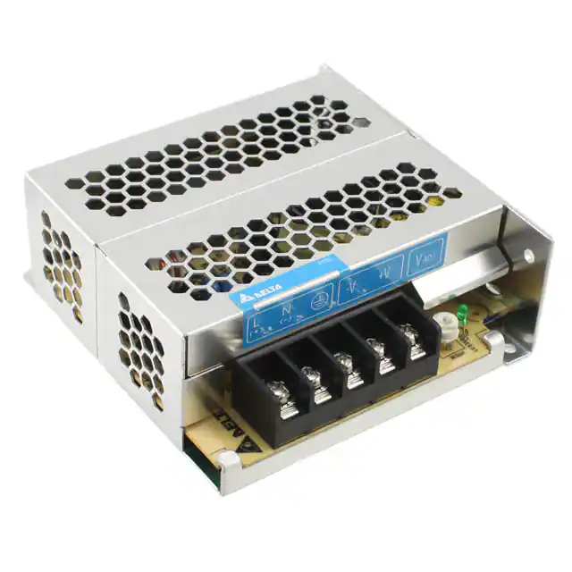
5 V 35 W 1 Phase / PMC-05V035W1A□
PMC
Highlights & Features
•
•
•
•
•
•
Universal AC input voltage range
Power will not de-rate for the entire input voltage range
Full corrosion resistant aluminium casing
Conforms to harmonic current IEC/EN 61000-3-2, Class A
High MTBF > 700,000 hrs per Telcordia SR-332
Safety approval according to IEC/UL 60950-1,
IEC/EN/UL 62368-1 and EMI to EN 55032, Class B
Safety Standards
CB Certified for worldwide use
Model Number:
PMC-05V035W1A☐
Unit Weight:
0.18 kg (0.40 lb)
Dimensions (L x W x H): 98 x 97 x 38 mm
(3.86 x 3.82 x 1.50 inch)
General Description
Delta’s PMC series of panel mount power supply offers a nominal output voltage of 5 V, a wide temperature range from -10°C to +70°C
and a highly dependable minimum hold-up time. The state-of-the-art design is made to withstand harsh industrial environments. What
makes the product stands out from the crowd is its lightweight full aluminum body design, which can withstand shock and vibration
according to IEC 60068-2. The PMC series also offers overvoltage and overload protection. Using a wide input voltage range design, it
is compatible worldwide. The input also includes DC operating voltage from 125-375 Vdc. Best of all, this excellent design and quality
does not come with a big price tag.
Model Information
PMC Panel Mount Power Supply
Model Number
Input Voltage Range
Rated Output Voltage
Rated Output Current
PMC-05V035W1A☐
85-264 Vac (125-375 Vdc)
5 Vdc
7.0 A
Model Numbering
PM
C–
05V
035W
1
A
□
Panel Mount
Product Type
C – Enclosed
Output Voltage
Output Power
Single Phase
No PFC
Connector Type
A – Terminal Block
J – IP20 Connector*
*Options
A
1
J
All parameters are specified at 25°C ambient and AC input unless otherwise indicated.
www.DeltaPSU.com (October 2021, Rev. 06)
�TECHNICAL DATASHEET
PMC Panel Mount Power Supply
5 V 35 W 1 Phase / PMC-05V035W1A□
Specifications
Input Ratings / Characteristics
Nominal Input Voltage
100-240 Vac
Input Voltage Range
85-264 Vac
Nominal Input Frequency
50-60 Hz
Input Frequency Range
47-63 Hz
Nominal DC Input Voltage
125-250 Vdc
DC Input Voltage Range*
125-375 Vdc
Input Current
< 0.9 A @ 115 Vac, < 0.8 A @ 230 Vac
Efficiency at 100% Load
> 78% @ 115 Vac, > 79% @ 230 Vac
Max Power Dissipation
0% load
< 0.3 W @ 115 Vac, < 0.7 W @ 230 Vac
100% load
< 9.9 W @ 115 Vac, < 9.3 W @ 230 Vac
Max Inrush Current
< 30 A @ 115 Vac, < 60 A @ 230 Vac
Leakage Current
< 1 mA @ 240 Vac
*Safety approval according to IEC/EN/UL 60950-1 and IEC/EN/UL 62368-1.
Output Ratings / Characteristics**
Nominal Output Voltage
5 Vdc
Factory Set Point Tolerance
5 Vdc ± 2%
Output Voltage Adjustment Range
4.75-5.5 Vdc
Output Current
7.0 A (35 W max.)
Output Power
35 W
Line Regulation
< 0.5% (@ 85-264 Vac input, 100% load)
Load Regulation
< 1.0% (@ 85-264 Vac input, 0-100% load)
PARD*** (20 MHz)
< 70 mVpp
Rise Time
< 30 ms @ nominal input (100% load)
Start-up Time
< 2500 ms @ nominal input (100% load)
Hold-up Time
> 15 ms @ 115 Vac, > 80 ms @ 230 Vac (100% load)
Dynamic Response
(Overshoot & Undershoot O/P Voltage)
± 5% @ 85-264 Vac input, 0-100% load
(Slew Rate: 0.1 A/μs, 50% duty cycle @ 5 Hz to 1 KHz)
Start-up with Capacitive Loads
6,600 µF Max
**For power de-rating from 50°C to 70°C, see power de-rating on page 3.
***PARD is measured with an AC coupling mode, 5 cm wires, and in parallel with 0.1 μF ceramic capacitor & 47 μF electrolytic capacitor.
2
All parameters are specified at 25°C ambient and AC input unless otherwise indicated.
www.DeltaPSU.com (October 2021, Rev. 06)
�TECHNICAL DATASHEET
PMC Panel Mount Power Supply
5 V 35 W 1 Phase / PMC-05V035W1A□
Mechanical
Case Chassis / Cover
Aluminium
Dimensions (L x W x H)
98 x 97 x 38 mm (3.86 x 3.82 x 1.50 inch)
Unit Weight
0.18 kg (0.40 lb)
Indicator
Green LED
Cooling System
Terminal
Wire
DC OK
Convection
PMC-05V035W1AA
M3.5 x 5 Pins (Rated 300 V/15 A)
PMC-05V035W1AJ
M3.5 x 5 Pins (Rated 300 V/20 A)
PMC-05V035W1AA
AWG 20-14
PMC-05V035W1AJ
AWG 20-12
Noise (1 Meter from power supply)
Sound Pressure Level (SPL) 50°C de-rate power by 2.5% / °C
Operating Humidity
5 to 95% RH (Non-Condensing)
Operating Altitude
0 to 3,000 Meters (9,840 ft)
Shock Test
Non-Operating
IEC 60068-2-27, 30G (300 m/S²) for a duration of 18ms,
1 times per direction, 6 times in total
Vibration
Non-Operating
IEC 60068-2-6, 10 Hz to 150 Hz @ 50 m/S² (5G peak);
20 min per axis for all X, Y, Z direction
Over Voltage Category
II
Pollution Degree
2
Protections
Overvoltage
< 6.5 V ±10%, SELV output, Hiccup Mode,
Non-Latching (Auto-Recovery)
Overload / Overcurrent
> 120% of rated load current, Hiccup Mode,
Non-Latching (Auto-Recovery)
Over Temperature
< 75°C Surrounding Air Temperature @ 100% load,
Non-Latching (Auto-Recovery)
Short Circuit
Hiccup Mode, Non-Latching
(Auto-Recovery when the fault is removed)
Internal Fuse at L pin
T3.15 AH
Degree of Protection
IP 20 (PMC-05V035W1AJ)
Protection Against Shock
Class I with PE* connection
*PE: Primary Earth
Reliability Data
MTBF
> 700,000 hrs. as per Telcordia SR-332
I/P: 115 Vac & 230 Vac, O/P: 100% load, Ta: 25°C
Expected Cap Life Time
10 years (115 Vac & 230 Vac, 50% load @ 40°C)
3
All parameters are specified at 25°C ambient and AC input unless otherwise indicated.
www.DeltaPSU.com (October 2021, Rev. 06)
�TECHNICAL DATASHEET
PMC Panel Mount Power Supply
5 V 35 W 1 Phase / PMC-05V035W1A□
Safety Standards / Directives
Safety Entry Low Voltage
Electrical Safety
SELV (IEC 60950-1)
SIQ Bauart
UL/cUL recognized
CB Scheme
UKCA
KC
EN 62368-1
UL 60950-1 and CSA C22.2 No. 60950-1 (File No. E191395)
UL 62368-1 and CSA C22.2 No. 62368-1 (File No. E191395)
IEC 60950-1, IEC 62368-1
BS EN 62368-1
K 60950-1 (for PMC-05V035W1AA)
CCC
GB/T9254, GB17625.1 and GB4943.1
仅适用于海拔 2000m 以下地区安全使用
CE
In conformance with EMC Directive 2014/30/EU and
Low Voltage Directive 2014/35/EU
UKCA
In conformance with Electrical Equipment (Safety) Regulations
2016 No. 1011 and
The Electromagnetic Compatibility Regulations 2016 No. 1091
3.0 KVac
Galvanic Isolation
Input to Output
Input to Ground
1.5 KVac
Output to Ground
0.5 KVac
EMC
Emissions (CE & RE)
Generic Standards: CISPR 32, EN/BS EN 55032,
KN 32 (for PMC-05V035W1AA), FCC Title 47: Class B,
GB 9254
Immunity
Generic Standards: EN/BS EN 55024,
KN 35 (for PMC-05V035W1AA)
Electrostatic Discharge
IEC 61000-4-2
Level 4 Criteria A1)
Air Discharge: 15 kV
Contact Discharge: 8 kV
Radiated Field
IEC 61000-4-3
Level 3 Criteria A1)
80 MHz-1 GHz, 10 V/M with 1 kHz tone / 80% modulation
Electrical Fast Transient / Burst
IEC 61000-4-4
Level 3 Criteria A1)
2 kV
Surge
IEC 61000-4-5
Level 3 Criteria A1)
Common Mode2): 2kV
Differential Mode3): 1 kV
Conducted
IEC 61000-4-6
Level 3 Criteria A1)
150 kHz-80 MHz, 10 Vrms
Power Frequency Magnetic Fields
IEC 61000-4-8
Criteria A1)
10 A/Meter
Voltage Dips and Interruptions
IEC 61000-4-11
100% dip; 1 cycle (20 ms); Self Recoverable
Low Energy Pulse Test (Ring Wave)
IEC 61000-4-12
Level 3 Criteria A1)
Common Mode2): 2 kV
Differential Mode3): 1 kV
Harmonic Current Emission
IEC/EN/BS EN 61000-3-2, Class A
Voltage Fluctuation and Flicker
IEC/EN/BS EN 61000-3-3
1) Criteria A: Normal performance within the specification limits
2) Asymmetrical: Common mode (Line to earth)
3) Symmetrical: Differential mode (Line to line)
4
All parameters are specified at 25°C ambient and AC input unless otherwise indicated.
www.DeltaPSU.com (October 2021, Rev. 06)
�TECHNICAL DATASHEET
PMC Panel Mount Power Supply
5 V 35 W 1 Phase / PMC-05V035W1A□
Block Diagram
Device Description
PMC-05V035W1AA: Terminal Block
1)
2)
3)
5
PMC-05V035W1AJ: IP20 Connector
Input & Output terminal block connector
DC Voltage adjustment potentiometer
DC OK control LED (Green)
All parameters are specified at 25°C ambient and AC input unless otherwise indicated.
www.DeltaPSU.com (October 2021, Rev. 06)
�TECHNICAL DATASHEET
PMC Panel Mount Power Supply
5 V 35 W 1 Phase / PMC-05V035W1A□
Dimensions
PMC-05V035W1AA: Terminal Block
L x W x H: 98 x 97 x 38 mm (3.86 x 3.82 x 1.50 inch)
PMC-05V035W1AJ: IP20 Connector
L x W x H: 98 x 97 x 38 mm (3.86 x 3.82 x 1.50 inch)
6
All parameters are specified at 25°C ambient and AC input unless otherwise indicated.
www.DeltaPSU.com (October 2021, Rev. 06)
�TECHNICAL DATASHEET
PMC Panel Mount Power Supply
5 V 35 W 1 Phase / PMC-05V035W1A□
Engineering Data
Output Load De-rating VS Surrounding Air Temperature
Note
1.
2.
3.
4.
Fig. 1
De-rating for Vertical and Horizontal Mounting Orientation
> 50°C de-rate power by 2.5% / °C
5.
Power supply components may degrade, or
be damaged, when the power supply is
continuously used outside the shaded region,
refer to the graph shown in Fig. 1.
If the output capacity is not reduced when the
surrounding air temperature exceeds its
specification as defined on Page 3 under
“Environment”, the device may run into Over
Temperature Protection. When activated, the
output voltage will go into bouncing mode and
will recover when the surrounding air
temperature is lowered or the load is reduced
as far as necessary to keep the device in
working condition.
In order for the device to function in the
manner intended, it is also necessary to keep
a safety distance as recommended in the
safety instructions while the device is in
operation.
Depending on the surrounding air temperature
and output load delivered by the power
supply, the device housing can be very hot!
If the device has to be mounted in any other
orientation, please contact info@deltapsu.com
for more details.
Output Load De-rating VS Input Voltage
7
No output power de-rating across the entire
input voltage range
All parameters are specified at 25°C ambient and AC input unless otherwise indicated.
www.DeltaPSU.com (October 2021, Rev. 06)
�TECHNICAL DATASHEET
PMC Panel Mount Power Supply
5 V 35 W 1 Phase / PMC-05V035W1A□
Assembly & Installation
Ⓐ
Ⓑ
Ⓒ
Mounting holes for power supply assembly onto the mounting surface. Power supply shall be mounted on minimum 2 mounting
holes using M3 screw minimum 5 mm (0.20 inch) length.
This surface belongs to customer’s end system or panel where the power supply is mounted.
Connector
Side Mounting (Vertical)
Base Mounting (Vertical)
Fig. 2
Side Mounting (Horizontal)
Recommended Mounting Orientations
Installation of Mounting Accessories
Only use M3 screw ≤ 6 mm (0.24 inch) through the base mounting holes.
This is to keep a safe distance between the screw and internal components.
Recommended mounting tightening torque 4~8 Kgf.cm (3.47~6.94 lbf.in)
Safety Instructions
•
•
•
•
•
•
8
To ensure sufficient convection cooling, always maintain a safety distance of ≥ 20 mm from all ventilated surfaces while the device
is in operation.
The device is not recommended to be placed on low thermal conductive surface, for example, plastics.
Note that the enclosure of the device can become very hot depending on the ambient temperature and load of the power supply. Do
not touch the device while it is in operation or immediately after power is turned OFF. Risk of burning!
Do not touch the terminals while power is being supplied. Risk of electric shock.
Prevent any foreign metal, particles or conductors to enter the device through the openings during installation.
It can cause: Electric shock; Safety Hazard; Fire; Product failure
Warning: When connecting the device, secure Earth connection before connecting L and N. When disconnecting the device, remove
L and N connections before removing the Earth connection.
All parameters are specified at 25°C ambient and AC input unless otherwise indicated.
www.DeltaPSU.com (October 2021, Rev. 06)
�TECHNICAL DATASHEET
PMC Panel Mount Power Supply
5 V 35 W 1 Phase / PMC-05V035W1A□
Functions
Graph illustrating the Start-up Time, Rise Time, and Hold-up Time
Start-up Time
The time required for the output voltage to reach 90% of its final steady state set value, after the input voltage is applied.
Rise Time
The time required for the output voltage to change from 10% to 90% of its final steady state set value.
Hold-up Time
Time between the collapse of the AC input voltage, and the output falling to 95% of its steady state set value.
Inrush Current
Dynamic Response
Inrush current is the peak, instantaneous, input current measured
and, occurs when the input voltage is first applied. For AC input
voltages, the maximum peak value of inrush current will occur
during the first half cycle of the applied AC voltage. This peak value
decreases exponentially during subsequent cycles of AC voltage.
The power supply output voltage will remains within ±5% of its
steady state value, when subjected to a dynamic load from 0% to
100% of its rated current.
9
50% duty cycle / 5Hz to 1KHz
All parameters are specified at 25°C ambient and AC input unless otherwise indicated.
www.DeltaPSU.com (October 2021, Rev. 06)
�TECHNICAL DATASHEET
PMC Panel Mount Power Supply
5 V 35 W 1 Phase / PMC-05V035W1A□
Overload & Overcurrent Protections (Auto-Recovery)
Overvoltage Protection (Auto-Recovery)
The power supply’s Overload (OLP) and Over current (OCP)
Protections will be activated when output current (IO) exceeds its
specification as defined on Page 3 under “Protections”. In such
occurrence, the output voltage (VO) will start to droop and once the
power supply has reached its maximum power limit, the protection
is activated and the power supply will go into “Hiccup mode” (AutoRecovery). The power supply will recover once the fault condition
of the OLP and OCP is removed and IO is back within the
specifications.
The power supply’s overvoltage circuit will be activated when its
internal feedback circuit fails. The output voltage shall not exceed
its specifications defined on Page 3 under “Protections”.
Over Temperature Protection (Auto-Recovery)
It is not recommended to prolong the duration of IO when it is less
than OLP/OCP point, but greater than 100%, since it may cause
damage to the PSU.
As described in load de-rating section, the power supply also has
Over Temperature Protection (OTP). In the event of a higher
operating temperature at 100% load, the power supply will run into
OTP when the operating temperature is beyond what is
recommended in the de-rating graph. When activated, the output
voltage will go into bouncing mode until the temperature drops to
its normal operating temperature as recommended in the de-rating
graph.
Short Circuit Protection (Auto-Recovery)
The power supply’s output OLP/OCP function also provides
protection against short circuits. When a short circuit is applied, the
output current will operate in “Hiccup mode”, as shown in the
illustration in the OLP/OCP section on this page. The power supply
will return to normal operation after the short circuit is removed.
Others
Attention
Delta provides all information in the datasheets on an “AS IS” basis and does not offer any kind of warranty through the information for
using the product. In the event of any discrepancy between the information in the catalog and datasheets, the datasheets shall prevail
(please refer to www.DeltaPSU.com for the latest datasheets information). Delta shall have no liability of indemnification for any claim
or action arising from any error for the provided information in the datasheets. Customer shall take its responsibility for evaluation of using
the product before placing an order with Delta.
Delta reserves the right to make changes to the information described in the datasheets without notice.
Manufacturer and Authorized Representatives Information
Manufacturer
Thailand
Delta Electronics (Thailand) PCL.
909 Pattana 1 Rd., Muang, Samutprakarn, 10280 Thailand
Taiwan
Delta Electronics, Inc.
3 Tungyuan Road, Chungli Industrial Zone, Taoyuan County
32063, Taiwan
Authorized Representatives
The Netherlands
Delta Greentech (Netherlands) B.V.
Zandsteen 15, 2132 MZ Hoofddorp, The Netherlands
10
United Kingdom
Delta Electronics Europe Limited
1 Redwood Court, Peel Park Campus,
East Kilbride, Glasgow, G74 5PF, United Kingdom
All parameters are specified at 25°C ambient and AC input unless otherwise indicated.
www.DeltaPSU.com (October 2021, Rev. 06)
�