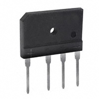
GBJ10005 - GBJ1010
10A GLASS PASSIVATED BRIDGE RECTIFIER Features
· · · · · · · Glass Passivated Die Construction High Case Dielectric Strength of 1500VRMS Low Reverse Leakage Current Surge Overload Rating to 170A Peak Ideal for Printed Circuit Board Applications Plastic Material - UL Flammability Classification 94V-0 UL Listed Under Recognized Component Index, File Number E94661
GBJ Dim A B
L K A B M
Min 29.70 19.70 17.00 3.80 7.30 9.80 2.00 0.90 2.30 4.40 3.40 3.10 2.50 0.60 10.80
Max 30.30 20.30 18.00 4.20 7.70 10.20 2.40 1.10 2.70 4.80 3.80 3.40 2.90 0.80 11.20
C D E G
Mechanical Data
· · · · · · · Case: Molded Plastic Terminals: Plated Leads, Solderable per MIL-STD-202, Method 208 Polarity: Molded on Body Mounting: Through Hole for #6 Screw Mounting Torque: 5.0 in-lbs Maximum Weight: 6.6 grams (approx.) Marking: Type Number
_
J H I
S P C R
N
H I J K L M N P R S
D
3.0 X 45°
G
E
E
All Dimensions in mm
Maximum Ratings and Electrical Characteristics
Single phase, half wave, 60Hz, resistive or inductive load. For capacitive load, derate current by 20%. Characteristic Peak Repetitive Reverse Voltage Working Peak Reverse Voltage DC Blocking Voltage RMS Reverse Voltage Average Forward Rectified Output Current @ TC= 110°C Non-Repetitive Peak Forward Surge Current, 8.3 ms single half-sine-wave superimposed on rated load (JEDEC method) Forward Voltage per element Peak Reverse Current at Rated DC Blocking Voltage I 2t Rating for Fusing (t < 8.3ms) (Note 1) @ IF = 5.0A @TC = 25°C @ TC = 125°C Symbol VRRM VRWM VR VR(RMS) IO IFSM VFM IR I 2t Cj RqJC Tj, TSTG GBJ 10005 50 35
@ TA = 25°C unless otherwise specified
GBJ 1001 100 70
GBJ 1002 200 140
GBJ 1004 400 280 10 170 1.05 10 500 120 55 1.4 -65 to +150
GBJ 1006 600 420
GBJ 1008 800 560
GBJ 1010 1000 700
Unit V V A A V mA A 2s pF °C/W °C
Typical Junction Capacitance per Element (Note 2) Typical Thermal Resistance, Junction to Case (Note 3) Operating and Storage Temperature Range
Notes:
1. Non-repetitive, for t > 1.0ms and < 8.3ms. 2. Measured at 1.0 MHz and applied reverse voltage of 4.0V DC. 3. Thermal resistance from junction to case per element. Unit mounted on 150 x 150 x 1.6mm copper plate heat sink.
DS21218 Rev. D-2
1 of 2
GBJ10005-GBJ1010
�10 8
with heatsink
IF, INSTANTANEOUS FORWARD CURRENT (A)
12
10
IO, AVERAGE RECTIFIED CURRENT (A)
1.0
TJ = 25°C
6
4 2
without heatsink Resistive or Inductive load
0.1
Pulse width = 300µs
0 25 50 75 100 125 150 TC, CASE TEMPERATURE (°C) Fig. 1 Forward Current Derating Curve
0.01 0 0.4 0.8 1.2 1.6 1.8 VF, INSTANTANEOUS FORWARD VOLTAGE (V) Fig. 2 Typical Forward Characteristics (per element)
180
IFSM, PEAK FWD SURGE CURRENT (A)
TJ = 150°C
120
Cj, JUNCTION CAPACITANCE (pF)
160
Single half-sine-wave (JEDEC method)
100
Tj = 25°C f = 1MHz
80
10
40
0
1
10
100
1 1 10 VR, REVERSE VOLTAGE (V) Fig. 4 Typical Junction Capacitance 100
NUMBER OF CYCLES AT 60 Hz Fig. 3 Maximum Non-Repetitive Surge Current
IR, INSTANTANEOUS REVERSE CURRENT (µA)
1000
TJ = 150°C
100
TJ = 125°C
TJ = 100°C
10
1.0
TJ = 25°C
0.1
0
20
40
60
80
100
120
140
PERCENT OF RATED PEAK REVERSE VOLTAGE (%) Fig. 5 Typical Reverse Characteristics
DS21218 Rev. D-2
2 of 2
GBJ10005-GBJ1010
�
很抱歉,暂时无法提供与“GBJ1002”相匹配的价格&库存,您可以联系我们找货
免费人工找货