1. 物料型号:
- MUR140 和 MUR160
2. 器件简介:
- 1.0A 超快速整流器,具有玻璃钝化芯片结构,超快速恢复时间,低正向电压降和高电流能力,承受高达35A峰值的浪涌过载额定值,适合自动化装配。
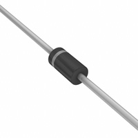
3. 引脚分配:
- 极性:阴极带
4. 参数特性:
- 最大额定值和电气特性包括但不限于:
- 峰值重复反向电压(VRRM):MUR140为400V,MUR160为600V
- 工作峰值反向电压(VRWM)/直流阻断电压(VR):MUR140为400V,MUR160为600V
- 有效值反向电压(VR(RMS)):MUR140为283V,MUR160为424V
- 平均整流输出电流(IO):在T=120°C时测量
- 非重复峰值正向浪涌电流(IFSM):8.3ms单半正弦波,叠加在额定负载上(JEDEC方法)
- 正向电压(VFM):在IF=1.0A, T=25°C和IF=1.0A, T=150°C时测量
- 峰值反向电流(IRM):在TA=25°C时,MUR140为5.0A,在TA=150°C时为150A
- 反向恢复时间(trr):MUR140为50ns和75ns
- 正向恢复时间(tfr):MUR140为50ns
- 典型结电容(C):MUR140为45pF
- 典型热阻,结到环境(ROJA):MUR140为72K/W
- 工作和存储温度范围(T,TSTG):-65至+175摄氏度
5. 功能详解:
- 提供了正向电流降额曲线、典型正向电流、浪涌电流降额曲线和典型反向电流等图表。
6. 应用信息:
- 适合自动化装配,具体应用场景未详细说明。
7. 封装信息:
- 封装材料:UL可燃性分类等级94V-0
- 机械数据:模塑塑料,DO-41塑料
- 端子:镀锡端子,可按照MIL-STD-202, 方法208焊接
- 标记:MUR140: R140,MUR160: R160
- 重量:大约0.35克
- 安装位置:任意