物料型号:
- SBG1630CT
- SBG1635CT
- SBG1640CT
- SBG1645CT
器件简介:
这些是16A表面贴装肖特基整流器,具有以下特点:
- 瞬态保护的防护环芯片结构
- 低功耗、高效率
- 高浪涌能力
- 高电流能力和低正向电压降
- 浪涌过载额定值高达175A峰值
- 适用于低电压、高频逆变器、自由轮和极性保护应用
- 无铅表面处理/符合RoHS标准
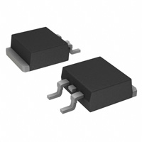
引脚分配:
- 封装类型:D2PAK
- 极性:见图示
- 标记:型号编号
参数特性:
- 工作峰值反向电压:SBG1630CT为30V,SBG1635CT为35V,SBG1640CT为40V,SBG1645CT为45V
- 直流阻断电压:同工作峰值反向电压
- 有效值反向电压:分别为21V、25V、28V和32V
- 平均整流输出电流:16A(@Tc= 95°C)
- 非重复峰值正向浪涌电流:175A(8.3ms单半正弦波叠加在额定负载上)
- 正向电压(元件):@IF=8.0A时,分别为0.55V
- 峰值反向电流:分别为1.0mA和50mA(@T=25°C和T=125°C)
- 典型总电容:分别为275pF
- 典型热阻(结到外壳):3.0°C/W
- 工作和存储温度范围:-65°C至+125°C
功能详解:
- 这些肖特基整流器适用于低电压、高频逆变器、自由轮和极性保护应用,具有高效率和高浪涌能力。
应用信息:
- 适用于低电压、高频逆变器、自由轮和极性保护应用。
封装信息:
- 封装类型:D2PAK
- 尺寸:包括A至M的不同尺寸参数,单位为毫米。
- 封装材料:模塑塑料,UL可燃性分类等级94V-0
- 湿度敏感度:根据J-STD-020C为1级
- 端子:镀锡,符合MIL-STD-202标准e3方法208