物料型号:
- SBL4030PT
- SBL4060PT
器件简介:
- 40A肖特基势垒整流器,具有肖特基势垒芯片结构,用于瞬态保护。
- 低功耗、高效率,高浪涌能力,高电流能力和低正向电压降。
- 适用于低电压、高频逆变器、自由轮和极性保护应用。
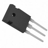
引脚分配:
- 封装类型为TO-3P,具体尺寸参数如下:
- A: 3.20-3.50mm
- B: 4.59-5.16mm
- C: 20.80-21.30mm
- D: 19.70-20.20mm
- E: 2.10-2.40mm
- G: 0.51-0.76mm
- H: 15.90-16.40mm
- J: 1.70-2.70mm
- K: 3.10-3.30mm
- L: 3.50-4.51mm
- M: 5.20-5.70mm
- N: 1.12-1.22mm
- P: 1.93-2.18mm
- Q: 2.97-3.22mm
- R: 11.70-12.80mm
- S: 4.30mm(典型值)
参数特性:
- 峰值重复反向电压:30V至60V不等,具体型号不同。
- 工作峰值反向电压:30V至60V不等,具体型号不同。
- 直流阻断电压:与峰值重复反向电压相同。
- 有效值反向电压:21V至42V不等,具体型号不同。
- 平均整流输出电流:在100°C时,部分型号为40A。
- 非重复峰值正向浪涌电流:部分型号为375A。
- 正向电压降:在20A和25°C时,部分型号为0.58V至0.70V不等。
- 额定直流阻断电压下的峰值反向电流:具体值未给出。
- 典型结电容:部分型号为800pF。
- 典型热阻(结到外壳):1.4°C/W。
- 工作温度范围:-55至+125°C。
- 存储温度范围:-55至+150°C。
功能详解:
- 该器件为肖特基整流器,用于低电压、高频应用,具有低正向压降和高效率的特点。
应用信息:
- 适用于低电压、高频逆变器、自由轮和极性保护应用。
封装信息:
- 封装类型为TO-3P,塑料材料符合UL可燃性分类等级94V-0。