1. 物料型号:
- 型号为:SBR20A200CTB
2. 器件简介:
- SBR20A200CTB是一款20A SBR® Super Barrier Rectifier,采用专利的Super Barrier Rectifier技术,具备低正向电压降、低漏电流、优秀的高温稳定性等特点。
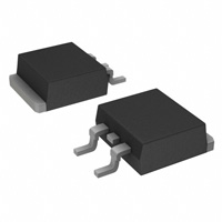
3. 引脚分配:
- D2PAK封装,共有三个引脚,分别为:阴极(Cathode)、阳极(Anode)和共同引脚(Common)。
4. 参数特性:
- 最大额定值:
- 峰值重复反向电压(VRRM)、工作峰值反向电压(VRWM)、DC阻断电压(VRM):200V
- 有效值反向电压(VR(RMS)):141V
- 平均整流输出电流在150°C时(Io):20A
- 非重复峰值正向浪涌电流(IFSM):180A
- 最大热阻(ReJC、ReJA):分别为4°C/W和43°C/W
- 工作和存储温度范围(TJ,TSTG):-65至+175℃
5. 功能详解:
- 该器件为单相半波60Hz的阻性或感性负载设计,对于电容性负载,需降低20%的电流。
- 正向电压降:在10A电流和25°C温度下为0.86V,在20A电流和25°C温度下为0.72V,在10A电流和125°C温度下为0.96V。
- 漏电流:在200V反向电压和25°C温度下为0.003mA,在125°C温度下为0.51mA。
6. 应用信息:
- 适用于需要高效能整流的场合,如电源、电机驱动等。
7. 封装信息:
- 采用D2PAK封装,具体尺寸如下:
- A:4.40至4.80毫米
- b:0.76至1.00毫米
- b2:1.17至1.47毫米
- C:0.36至0.50毫米
- c2:1.25至1.45毫米
- D:8.60至9.00毫米
- E:9.80至10.40毫米
- e:2.54毫米(典型值)
- L:14.60至15.80毫米
- L1:2.29至2.79毫米
- L2:1.27毫米(典型值)