TB0640L - TB3500L
30A BI-DIRECTIONAL SURFACE MOUNT THYRISTOR SURGE PROTECTIVE DEVICE Features
UNDER DEVELOPMENT
NEW PRODUCT
· · · · · ·
30A Peak Pulse Current @ 10/1000ms 150A Peak Pulse Current @ 8/20ms 58 - 320V Stand-Off Voltages Oxide-Glass Passivated Junction Bi-Directional Protection In a Single Device High Off-State impedance and Low On-State Voltage
B
A
Dim
SMB Min 4.06 3.30 1.96 0.15 5.21 0.05 2.01 0.76 Max 4.57 3.94 2.21 0.31 5.59 0.20 2.62 1.52 A B C D
Mechanical Data
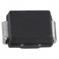
· · · · · · · · Case: SMB, Molded Plastic Plastic Material: UL Flammability Classification Rating 94V-0 Moisture sensitivity: Level 1 per J-STD-020A Terminals: Solder Plated Terminal Solderable per MIL-STD-202, Method 208 Polarity: None; Bi-Directional Devices Have No Polarity Indicator Weight: 0.093 grams (approx.) Marking: Date Code and Marking Code (See Page 4) Ordering Information: See Page 4
C
D
G
E F G H
H
F E
All Dimensions in mm
Maximum Ratings
@ TA = 25°C unless otherwise specified
Single phase, half wave, 60Hz, resistive or inductive load. For capacitive load, derate current by 20%. Characteristic Non-Repetitive Peak Impulse Current Non-Repetitive Peak On-State Current Junction Temperature Range Storage Temperature Range Thermal Resistance, Junction to Lead Thermal Resistance, Junction to Ambient Typical Positive Temperature Coefficient for Breakdown Voltage @10/1000us @8.3ms (one-half cycle) Symbol Ipp ITSM Tj TSTG RqJL RqJA DVBR/DTj Value 30 15 -40 to +150 -55 to +150 30 120 0.1 Unit A A °C °C °C/W °C/W %/°C
Maximum Rated Surge Waveform
Waveform 2/10 us 8/20 us 10/160 us 10/700 us 10/560 us 10/1000 us Standard GR-1089-CORE IEC 61000-4-5 FCC Part 68 ITU-T, K20/K21 FCC Part 68 GR-1089-CORE Ipp (A) 200 150 100 60 50 30
0
IPP, PEAK PULSE CURRENT (%)
100
Peak Value (Ipp) tr = rise time to peak value tp = decay time to half value Half Value
50
0
tr
tp
TIME
DS30359 Rev. 2 - 1
1 of 4
TB0640L - TB3500L
�Electrical Characteristics
@ TA = 25°C unless otherwise specified On-State Voltage @ IT = 1 A VT (V) 3.5 3.5 3.5 3.5 3.5 3.5 3.5 3.5 3.5 3.5 3.5
NEW PRODUCT
Part Number
Rated Repetitive Off-State Voltage VDRM (V)
Off-State Leakage Current @ VDRM IDRM (uA) 5 5 5 5 5 5 5 5 5 5 5
Breakover Voltage VBO (V) 77 88 98 130 160 180 220 265 300 350 400
Breakover Current IBO Min (mA) 50 50 50 50 50 50 50 50 50 50 50 Max (mA) 800 800 800 800 800 800 800 800 800 800 800
Holding Current IH Min (mA) 150 150 150 150 150 150 150 150 150 150 150 Max (mA) 800 800 800 800 800 800 800 800 800 800 800
Off-State Capacitance CO (pF) 100 100 100 60 60 60 60 40 40 40 40
Marking Code
TB0640L TB0720L TB0900L TB1100L TB1300L TB1500L TB1800L TB2300L TB2600L TB3100L TB3500L
58 65 75 90 120 140 160 190 220 275 320
T064L T072L T090L T110L T130L T150L T180L T230L T260L T310L T350L
Symbol VDRM IDRM VBR IBR VBO IBO IH VT IPP CO Notes: Stand-off Voltage
Parameter Leakage current at stand-off voltage Breakdown voltage Breakdown current Breakover voltage Breakover current Holding current On state voltage Peak pulse current Off-state capacitance NOTE: 2 NOTE: 1
1. IH > (VL/RL) If this criterion is not obeyed, the TSPD triggers but does not return correctly to high-resistance state. The surge recovery time does not exceed 30ms. 2. Off-state capacitance measured at f = 1.0MHz, 1.0VRMS signal, VR = 2VDC bias.
I IPP
IBO IH IBR IDRM VT VDRM VBR VBO
V
UNDER DEVELOPMENT
DS30359 Rev. 2 - 1
2 of 4
TB0640L - TB3500L
�100
NORMALIZED BREAKDOWN VOLTAGE
1.2
NEW PRODUCT
1.15
VBR= (TJ) VBR = (TJ = 25°C)
10
1.1
1
1.05
0.1
VDRM = 50V
1
0.01
0.95
0.9
0.001 -25 0 25 50 75 100 125 150 TJ, JUNCTION TEMPERATURE (°C) Fig. 1 Off-State Current vs. Junction Temperature
-50
-25
0
25
50
75
100 125 150 175
TJ, JUNCTION TEMPERATURE (°C) Fig. 2 Relative Variation of Breakdown Voltage vs. Junction Temperature
1.1 NORMALIZED BREAKDOWN VOLTAGE
100
1.05
VBO = (TJ = 25°C)
IT, ON-STATE CURRENT (A)
VBO= (TJ)
10
1
Tj = 25°C
0.95
-50 -25 0 25 50 75 100 125 150 175 T , JUNCTION TEMPERATURE (ºC) J Fig. 3 Relative Variation of Breakover Voltage vs. Junction Temperature
2
1 1 2 3 4 5 6 7 8 9 VT, ON-STATE VOLTAGE (V) Fig. 4 On-State Current vs. On-State Voltage
1
NORMALIZED HOLDING CURRENT
1.5
1
NORMALIZED CAPACITANCE
CO= (VR) CO = (VR = 1V)
0.5
IH = (TJ) IH = (TJ = 25°C)
Tj = 25°C f = 1 Mhz VRMS = 1V
0 -50 -25 0 25 50 75 100 125
0.1 1 10 100
TJ, JUNCTION TEMPERATURE (°C) Fig. 5 Relative Variation of Holding Current vs. Junction Temperature
VR, REVERSE VOLTAGE (V) Fig. 6 Relative Variation of Junction Capacitance vs. Reverse Voltage Bias
UNDER DEVELOPMENT
DS30359 Rev. 2 - 1 3 of 4 TB0640L - TB3500L
�Ordering Information
(Note 3) Packaging Shipping
NEW PRODUCT
Device TB0640L-13 TB0720L-13 TB0900L-13 TB1100L-13 TB1300L-13 TB1500L-13 TB1800L-13 TB2300L-13 TB2600L-13 TB3100L-13 TB3500L-13 Notes:
SMB
3000/Tape & Reel
3. For Packaging Details, go to our website at http://www.diodes.com/datasheets/ap02007.pdf.
Marking Information
YWW XXXXX
XXXXX = Product Type Marking Code YWW = Date Code Marking Y = Year ex: 2 = 2002 WW = Week
Date Code Key Year Code 2002 2 2003 3 2004 4
UNDER DEVELOPMENT
DS30359 Rev. 2 - 1
4 of 4
TB0640L - TB3500L
�
很抱歉,暂时无法提供与“TB2300L-13”相匹配的价格&库存,您可以联系我们找货
免费人工找货