2N5172
2N5172 NPN
Version 2006-05-15 Power dissipation Verlustleistung
E BC
General Purpose Si-Epitaxial Planar Transistors Si-Epitaxial Planar-Transistoren für universellen Einsatz
NPN
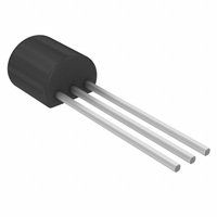
625 mW TO-92 (10D3) 0.18 g
16
Plastic case Kunststoffgehäuse
18
Weight approx. – Gewicht ca. Plastic material has UL classification 94V-0 Gehäusematerial UL94V-0 klassifiziert Standard packaging taped in ammo pack Standard Lieferform gegurtet in Ammo-Pack
2 x 2.54
Dimensions - Maße [mm]
Maximum ratings (TA = 25°C) Collector-Emitter-volt. – Kollektor-Emitter-Spannung Collector-Base-volt. – Kollektor-Basis-Spannung Emitter-Base-voltage – Emitter-Basis-Spannung Power dissipation – Verlustleistung Collector current – Kollektorstrom (dc) Junction temperature – Sperrschichttemperatur Storage temperature – Lagerungstemperatur B open E open C open VCEO VCBO VEBO Ptot IC Tj TS 25 V 25 V 5V
9
Grenzwerte (TA = 25°C) 2N5172
625 mW 1) 100 mA -55...+150°C -55…+150°C
Characteristics (Tj = 25°C) Min. DC current gain – Kollektor-Basis-Stromverhältnis VCE = 10 V, IC = 10 mA Small-Signal current gain – Kleinsignal-Stromverstärkung VCE = 10 V, IC = 1 mA, f = 1.0 kHz Collector-Base cutoff current – Kollektor-Basis-Reststrom VCB = 25 V (E open) VCB = 25 V, Tj = 100°C (E open) Collector-Emitter cutoff current – Kollektorreststrom VCE = 25 V (B-E short) Emitter-Base-cutoff current – Emitter-Basis-Reststrom VEB = 5 V (C open) IEBO – ICES – ICBO ICBO – – hfe 100 hFE 100
Kennwerte (Tj = 25°C) Typ. – – – – – – Max. 500 750 100 nA 10 µA 100 nA 100 nA
1
Valid if leads are kept at ambient temperature at a distance of 2 mm from case Gültig wenn die Anschlussdrähte in 2 mm Abstand vom Gehäuse auf Umgebungstemperatur gehalten werden http://www.diotec.com/
© Diotec Semiconductor AG
1
�2N5172 Characteristics (Tj = 25°C) Min. Collector-Emitter saturation voltage – Kollektor-Emitter-Sättigungsspg. 2) IC = 10 mA, IB = 1 mA IC = 10 mA, IB = 1 mA Base-Emitter-voltage – Basis-Emitter-Spannung VCE = 10 V, IC = 10 mA Gain-Bandwidth Product – Transitfrequenz VCE = 5 V, IC = 2 mA, f = 20 MHz Collector-Base Capacitance – Kollektor-Basis-Kapazität VCB = 5 V, IE =ie = 0, f = 1 MHz Thermal resistance junction to ambient air Wärmewiderstand Sperrschicht – umgebende Luft CCB0 RthA 1.6 pF – < 200 K/W 1) 10 pF fT – 120 MHz – VBE(on) 0.5 V – 1.2 V VCEsat VBEsat – – – 0.75 V 0.25 V – Base-Emitter saturation voltage – Basis-Emitter-Sättigungsspannung 2) Kennwerte (Tj = 25°C) Typ. Max.
120 [%] 100
80
60
40
20 Ptot 0 0 TA 50 100 150 [°C]
Power dissipation versus ambient temperature 1) Verlustleistung in Abh. von d. Umgebungstemp.1)
2 1
Tested with pulses tp = 300 µs, duty cycle ≤ 2% – Gemessen mit Impulsen tp = 300 µs, Schaltverhältnis ≤ 2% Valid if leads are kept at ambient temperature at a distance of 2 mm from case Gültig wenn die Anschlussdrähte in 2 mm Abstand vom Gehäuse auf Umgebungstemperatur gehalten werden http://www.diotec.com/ © Diotec Semiconductor AG
2
�
很抱歉,暂时无法提供与“2N5172”相匹配的价格&库存,您可以联系我们找货
免费人工找货