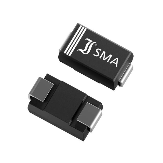
CL15M35 ... CL40M35
CL15M35 ... CL40M35
IPnom = 15 ... 40 mA
VAK = 90V
SMD Current Limiting Diodes
SMD Strom-Begrenzer-Dioden
Ptot = 1 W
Tjmax = 150°C
Version 2020-11-04
Typical Applications
Low power LED drivers
and battery chargers
Constant current regulators
for simple sensor circuits
Power supply for µController
Commercial grade
Suffix -Q: AEC-Q101 compliant 1)
Suffix -AQ: in AEC-Q101 qualification 1)
± 0.2
2.2 ± 0.2
2.1 ± 0.2
5
1
1.5 ±0.1
Type
Typ
Besonderheiten
VAK bis zu 90 V
Parallelbetrieb für höheres IP
Konform zu RoHS, REACH,
Konfliktmineralien 1)
RoHS
Pb
EE
WE
2.7 ± 0.2
Features
VAK up to 90 V
Parallel operation for higher IP
Compliant to RoHS, REACH,
Conflict Minerals 1)
0.15
± 0.3
EL
V
SMA
~ DO-214AC
Typische Anwendungen
LED-Treiber und Akku-Lader
mit kleiner Leistung
Konstantstromquellen für
einfache Sensorschaltungen
Stromversorgung für µController
Standardausführung
Suffix -Q: AEC-Q101 konform 1)
Suffix -AQ: in AEC-Q101 Qualifikation 1)
Mechanical Data 1)
4.5
± 0.3
Mechanische Daten 1)
Taped and reeled
7500 / 13“
Weight approx.
Dimensions - Maße [mm]
Gegurtet auf Rolle
0.07 g
Gewicht ca.
Case material
UL 94V-0
Gehäusematerial
Solder & assembly conditions
260°C/10s
Löt- und Einbaubedingungen
MSL = 1
Maximum ratings 2)
Grenzwerte 2)
Power dissipation – Verlustleistung
TA = 50°C
Ptot
1 W 3)
Peak operating voltage – Maximale Arbeitsspannung
VAK
90 V
Operating junction temperature – Sperrschichttemperatur
Storage temperature – Lagerungstemperatur
Tj
TS
-50...+150°C
-50...+150°C
Characteristics 4)
Kennwerte 4)
Type
Typ
Regulator current
Begrenzerstrom
at/bei VT = 10 V 5)
[mA]
Limiting voltage
Grenzspannung
at/bei IL = 80% IP
Temperature coefficient
Temperaturkoeffizient
of/von IP 6)
at/bei VT = 10 V
IPmin
IPnom
IPmax
VL [V]
αIP [10-4 /°C]
CL15M35/-AQ
12
15
17
3
–26…0
CL20M35/-AQ
17
20
23
3
–26…0
CL40M35/-AQ
34
40
46
3
–26…0
Reverse voltage – Sperrspannung
Junction capacitance – Sperrschichtkapazität
VR = 0 V
Typ. thermal resistance junction to ambient – Typ. Wärmewiderstand Sperrschicht – Umgebung
Typ. thermal resistance junction to terminal – Typ. Wärmewiderstand Sperrschicht – Anschluss
1
2
3
4
5
6
VR
0.5 V
CT
5 pF
RthA
RthT
70 K/W 3)
30 K/W
Please note the detailed information on our website or at the beginning of the data book
Bitte beachten Sie die detaillierten Hinweise auf unserer Internetseite bzw. am Anfang des Datenbuches
TA = 25°C unless otherwise specified – TA = 25°C wenn nicht anders angegeben
Mounted on P.C. board with 25 mm2 copper pads per terminal – Montage auf Leiterplatte mit 25 mm2 Lötpads je Anschluss
See Fig. 1 – Siehe Fig. 1
At max VAK, IP might exceed the rated value Ipmax – Bei maximalem VAK kann IP evtl. IPmax überschreiten
For compensation, see Fig. 5 – Zur Kompensation siehe Fig. 5
© Diotec Semiconductor AG
http://www.diotec.com/
1
�CL15M35 ... CL40M35
Fig. 1
Characteristic and symbol
Kennlinie und Symbol
120
[%]
100
IF
80
IP
IL
60
40
VR
VL
VT
VAK
VF
20
Ptot
0
IF
TA
50
100
150
[°C]
1
Application Notes
Applikationshinweise
~
Fig. 2
Low power LED driver or
battery charger
0
Power dissipation versus ambient temperature )
Verlustleistung in Abh. von d. Umgebungstemp.1 )
VF
_
+
~
Fig. 2
LED-Treiber oder Akku-Lader
mit kleiner Leistung
Fig. 3
Stromversorgung für
µController mit Shunt-Regler
(z. B. MMTL431A)
Fig. 3
Power supply for µController
using Shunt Regulator
(e. g. MMTL431A)
Fig. 4
Parallel operation for
higher currents
Fig. 4
Parallelbetrieb für
höhere Ströme
Fig. 5
Compensation of
temperature drift by
parallel resistor
Fig. 5
Kompensation der
Temperaturdrift durch
Parallelwiderstand
1
Disclaimer: See data book page 2 or website
The application notes describe circuit proposals and shall not be considered as assured and proven solution for any device. No warranty or guarantee,
expressed or implied is made regarding the availability, performance or suitability of any device, circuit etc, neither does it convey any license under its
patent rights of others.
Haftungssauschluss: Siehe Datenbuch Seite 2 oder Internet
Die Applikationshinweise zeigen Schaltungsbeispiele und dienen allein deren Beschreibung. Sie sind nicht als zugesagte oder geprüfte Eigenschaften im
Rechts-Sinne zu verstehen. Es wird keine Gewähr bezüglich Liefermöglichkeit, Ausführung oder Einsatzmöglichkeit der Bauelemente übernommen, noch
dass die angegebenen Bauelemente, Baugruppen, Schaltungen etc. frei von Schutzrechten sind.
1
2
Mounted on P.C. board with 25 mm2 copper pads per terminal – Montage auf Leiterplatte mit 25 mm2 Lötpads je Anschluss
http://www.diotec.com/
© Diotec Semiconductor AG
�
很抱歉,暂时无法提供与“CL20M35”相匹配的价格&库存,您可以联系我们找货
免费人工找货