F5K120
F5K120
Protectifiers® – LowVF-Rectifier with Overvoltage Protection Protectifiers® – LowVF-Gleichrichter mit Überspannungs-Schutz Version 2010-05-31 Nominal current Nennstrom
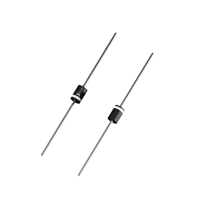
Ø 5.4
±0.1
5A 120 V Ø 5.4 x 7.5 [mm] 1.0 g
Stand off voltage Sperrspannung Plastic case Kunststoffgehäuse Weight approx. Gewicht ca. Plastic material has UL classification 94V-0 Gehäusematerial UL94V-0 klassifiziert Standard packaging taped in ammo pack Standard Lieferform gegurtet in Ammo-Pack
62.5 ±0.5
Ø 1.2 ±0.05
Dimensions - Maße [mm]
Low forward losses, high reverse pulse power capability Niedrige Durchlass-Verluste, hohe Rückwärts-Pulsbelastbarkeit Maximum ratings and Charactistics (TJ = 25°C) Type Typ Stand-off voltage Sperrspannung VWM [V] F5K120 120 Max. rev. current Max. Sperrstrom at/bei VWM ID [µA] 5 Grenz- und Kennwerte (TJ = 25°C) Breakdown voltage Abbruch-Spannung VBR min [V] 130 @ IT [mA] 5 Forward voltage Durchlass-Spannung VF [V] 1) IF = 5A < 0.95
Max. average forward rectified current, R-load Dauergrenzstrom in Einwegschaltung mit R-Last Total steady state power dissipation Gesamtverlustleistung im Dauerbetrieb Repetitive peak forward current Periodischer Spitzenstrom Peak forward surge current, 50/60 Hz half sine-wave Stoßstrom für eine 50/60 Hz Sinus-Halbwelle Rating for fusing, t < 10 ms Grenzlastintegral, t < 10 ms Junction temperature – Sperrschichttemperatur in DC forward mode – bei Gleichstrom-Durchlassbetrieb Storage temperature – Lagerungstemperatur
7.5 ±0.1
Type
TA = 50°C TA = 50°C f > 15 Hz TA = 25°C TA = 25°C
IFAV Ptot IFRM IFSM i2t Tj Tj TS
5 A 2) 5W 50 A 1) 250/280 A 200 A2s -50...+175°C +200°C -50...+175°C
1 2
Tj = 25°C Valid, if leads are kept at ambient temperature at a distance of 10 mm from case Gültig, wenn die Anschlussdrähte in 10 mm Abstand von Gehäuse auf Umgebungstemperatur gehalten werden http://www.diotec.com/
© Diotec Semiconductor AG
1
�F5K120 Characteristics Leakage current Sperrstrom ESD rating according to JESD22-A114 / contact discharge ESD-Festigkeit gemäß JESD22-A114 / Kontaktentladung Peak pulse power dissipation Impuls-Verlustleistung Max. reverse peak pulse current Max. Impuls-Strom in Sperr-Richtung Reverse recovery time Sperrverzug Thermal resistance junction to ambient air Wärmewiderstand Sperrschicht – umgebende Luft Thermal resistance junction to leads Wärmewiderstand Sperrschicht – Anschlussdraht Tj = 25°C Tj = 100°C C = 100pF VR = VWM VR = VWM R = 1.5kΩ PPPM IPPM trr RthA RthL IR IR Kennwerte < 5 µA < 100 µA 20 kV 700 W 100 A < 300 ns < 25 K/W 3) < 10 K/W
10/1000µs pulse 1) TA = 25°C 8/20µs pulse 2) TA = 25°C IF = 0.5 A through/über IR = 1 A to IR = 0.25 A
120 [%] 100
103
[A]
10 80
2
Tj = 125°C
60
10
Tj = 25°C
40 1 20 IFAV 0 0 TC 50 100 150 [°C] IF 10-1
Rated forward current vs. temp. of the case Zul. Richtstrom in Abh. v. d. Temp. Des Gehäuses
250a-(7.5a-1,05v)
0.4
VF
0.8
1.0
1.2
1.4
[V] 1.8
Forward characteristics (typical values) Durchlasskennlinien (typische Werte)
1 2 3
See curve IPP = f (t) 10/1000µs – Siehe Kurve IPP = f (t) 10/1000µs See curve IPP = f (t) 8/20µs – Siehe Kurve IPP = f (t) 8/20µs Valid, if leads are kept at ambient temperature at a distance of 10 mm from case Gültig, wenn die Anschlussdrähte in 10 mm Abstand von Gehäuse auf Umgebungstemperatur gehalten werden http://www.diotec.com/ © Diotec Semiconductor AG
2
�F5K120
tr = 10 µs 100 [%] 80 100 [%] 80
tr = 8 µs
60 PPPM/2
IPPM/2
60 PPPM/2
IPPM/2
40 IPP 20 PPP 0 0
40 IPP 20 PPP 1 2 3 [ms] 4 0 0
tP t
10/1000µs - pulse waveform 10/1000µs - Impulsform
tP t 20 40 60 [µs]
8/20µs - pulse waveform 8/20µs - Impulsform
© Diotec Semiconductor AG
http://www.diotec.com/
3
�
很抱歉,暂时无法提供与“F5K120”相匹配的价格&库存,您可以联系我们找货
免费人工找货- 国内价格 香港价格
- 1700+1.728121700+0.22366
- 国内价格
- 1+1.94044
- 10+1.52240
- 100+1.03849
- 1700+0.86601
- 3400+0.86122
- 8500+0.84924