GBI25A ... GBI25M
GBI25A ... GBI25M
Silicon-Bridge-Rectifiers Silizium-Brückengleichrichter Version 2006-01-04
4.8
±0.2
30
±0.2
±0.2
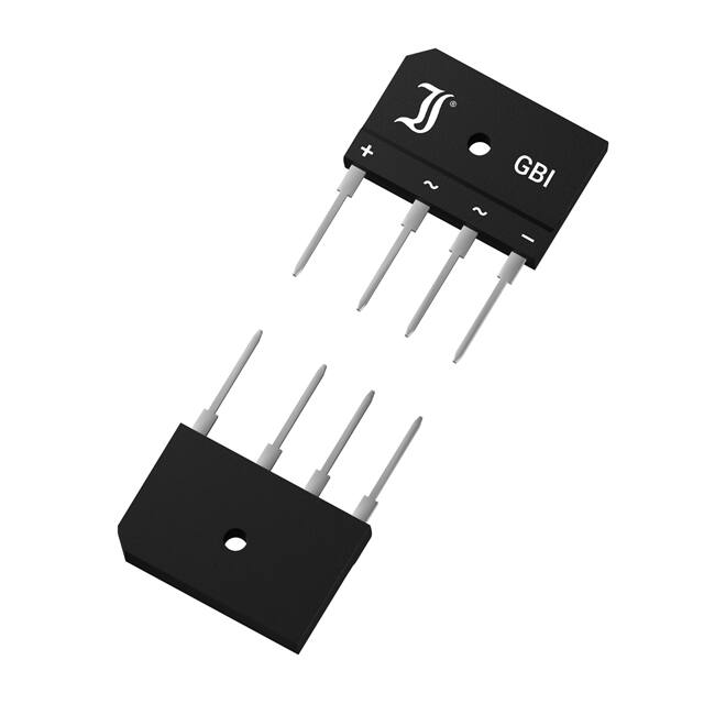
Nominal current Nennstrom Repetitive peak reverse voltage Periodische Spitzensperrspannung Plastic case Kunststoffgehäuse
25 A 50...1000 V 30 x 3.6 x 18 [mm] 7g
3.8
Type Typ
±0.2
20
+
2.2 1.0 10
~
~
4
–
±0.2
11
±0.2
3.1
17.5±0.2
±0.2
Weight approx. – Gewicht ca. Plastic material has UL classification 94V-0 Gehäusematerial UL94V-0 klassifiziert Standard packaging bulk Standard Lieferform lose im Karton
2x7.5
0.8
Dimensions - Maße [mm]
Recognized Product – Underwriters Laboratories Inc.® File E175067 Anerkanntes Produkt – Underwriters Laboratories Inc.® Nr. E175067
Maximum ratings Type Typ GBI25A GBI25B GBI25D GBI25G GBI25J GBI25K GBI25M Repetitive peak forward current Periodischer Spitzenstrom Peak forward surge current, 50/60 Hz half sine-wave Stoßstrom für eine 50/60 Hz Sinus-Halbwelle Rating for fusing, t < 10 ms Grenzlastintegral, t < 10 ms Operating junction temperature – Sperrschichttemperatur Storage temperature – Lagerungstemperatur Admissible torque for mounting Zulässiges Anzugsdrehmoment M3 Max. alternating input voltage Max. Eingangswechselspannung VVRMS [V] 35 70 140 280 420 560 700 f > 15 Hz TA = 25°C TA = 25°C
Grenzwerte Repetitive peak reverse voltage Periodische Spitzensperrspannung VRRM [V] 1) 50 100 200 400 600 800 1000 IFRM IFSM i2t 60 A 2) 300/340 A 450 A2s -50...+150°C -50...+150°C 5 ± 10% lb.in. 0.5 ± 10% Nm
Tj TS
1 2
Valid for one branch – Gültig für einen Brückenzweig Valid, if leads are kept to ambient temperature TA = 50°C at a distance of 5 mm from case Gültig, wenn die Anschlüsse in 5 mm vom Gehäuse auf Umgebungstemperatur TA = 50°C gehalten werden http://www.diotec.com/
© Diotec Semiconductor AG
1
�GBI25A ... GBI25M Characteristics Max. rectified current without cooling fin Dauergrenzstrom ohne Kühlblech Max. rectified current with forced cooling Dauergrenzstrom mit forcierter Kühlung Forward voltage – Durchlass-Spannung Leakage current – Sperrstrom Thermal resistance junction to ambient air Wärmewiderstand Sperrschicht – umgebende Luft Thermal resistance junction to case Wärmewiderstand Sperrschicht – Gehäuse TA = 50°C TC = 100°C Tj = 25°C Tj = 25°C R-load C-load R-load C-load IF = 12.5 A VR = VRRM IFAV IFAV IFAV IFAV VF IR RthJA RthJC Kennwerte 4.2 A 1) 3.5 A 1) 25.0 A 20.0 A < 1.1 V 2) < 10 µA < 12 K/W 1) < 1.2 K/W
Type Typ GBI25A GBI25B GBI25D GBI25G GBI25J GBI25K GBI25M
Max. admissible load capacitor Max. zulässiger Ladekondensator CL [µF] 20000 10000 5000 2500 1500 1000 800
Min. required protective resistor Min. erforderl. Schutzwiderstand RL [Ω] 0.2 0.4 0.8 1.6 2.4 3.2 4.0
120 [%] 100
103 [A] 102
Tj = 125°C
80 10
Tj = 25°C
60
40 1 20 IFAV 0 0 TC 50 100 150 [°C] IF 10
-1
270a-(12a-1v)
0.4
VF
0.8
1.0
1.2
1.4
[V] 1.8
Rated forward current vs. temp. of the case Zul. Richtstrom in Abh. v. d. Gehäusetemperatur
Forward characteristics (typical values) Durchlasskennlinien (typische Werte)
1 2
Valid, if leads are kept to ambient temperature at a distance of 5 mm from case Gültig, wenn die Anschlüsse in 5 mm Abstand vom Gehäuse auf Umgebungstemperatur gehalten werden Valid for one branch − Gültig für einen Brückenzweig http://www.diotec.com/ © Diotec Semiconductor AG
2
�
很抱歉,暂时无法提供与“GBI25G”相匹配的价格&库存,您可以联系我们找货
免费人工找货