MMBTA55 ... MMBTA56
MMBTA55 ... MMBTA56 PNP
Version 2006-08-09 Power dissipation – Verlustleistung
2.9 0.4
±0.1
General Purpose Si-Epitaxial PlanarTransistors Si-Epitaxial Planar-Transistoren für universellen Einsatz
PNP
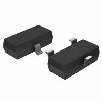
250 mW SOT-23 (TO-236) 0.01 g
1.1
3
Plastic case Kunststoffgehäuse
1.3 ±0.1
Type Code
1 2
2.5 max
Weight approx. – Gewicht ca. Plastic material has UL classification 94V-0 Gehäusematerial UL94V-0 klassifiziert Standard packaging taped and reeled Standard Lieferform gegurtet auf Rolle
1.9
Dimensions - Maße [mm] 1=B 2=E 3=C
Maximum ratings (TA = 25°C) Collector-Emitter-volt. – Kollektor-Emitter-Spannung Collector-Base-voltage – Kollektor-Basis-Spannung Emitter-Base-voltage – Emitter-Basis-Spannung Power dissipation – Verlustleistung Collector current – Kollektorstrom (dc) Base current – Basisstrom Peak Base current – Basis-Spitzenstrom Junction temperature – Sperrschichttemperatur Storage temperature – Lagerungstemperatur B open E open C open - VCEO - VCBO - VEBO Ptot - IC - IB - IBM Tj TS
Grenzwerte (TA = 25°C) MMBTA55 60 V 60 V 4V 250 mW 1) 500 mA 100 mA 200 mA -55...+150°C -55…+150°C MMBTA56 80 V 80 V
Characteristics (Tj = 25°C) Min. DC current gain – Kollektor-Basis-Stromverhältnis )
2
Kennwerte (Tj = 25°C) Typ. – – – – Max. – – 0.25 V 1.2 V
- IC = 10 mA, - VCE = 1 V - IC = 100 mA, - VCE = 1 V - IC = 100 mA, - IB = 10 mA Base-Emitter voltage – Basis-Emitter-Spannung - IC = 100 mA, - VCE = 1 V
hFE hFE - VCEsat - VBE
100 100 – –
Collector-Emitter saturation voltage – Kollektor-Emitter-Sättigungsspg. 2)
1 2
Mounted on P.C. board with 3 mm2 copper pad at each terminal Montage auf Leiterplatte mit 3 mm2 Kupferbelag (Lötpad) an jedem Anschluss Tested with pulses tp = 300 µs, duty cycle ≤ 2% – Gemessen mit Impulsen tp = 300 µs, Schaltverhältnis ≤ 2% http://www.diotec.com/
© Diotec Semiconductor AG
1
�MMBTA55 ... MMBTA56 Characteristics (Tj = 25°C) Collector-Base cutoff current – Kollektor-Basis-Reststrom - VCB = 60 V, (E open) - VCB = 80 V, (E open) - VEB = 4 V, (C open) Gain-Bandwidth Product – Transitfrequenz - IC = 100 mA, - VCE = 1 V, f = 100 MHz Thermal resistance junction to ambient air Wärmewiderstand Sperrschicht – umgebende Luft Recommended complementary NPN transistors Empfohlene komplementäre NPN-Transistoren Marking - Stempelung fT RthA 50 MHz – < 420 K/W 1) MMBTA05, MMBTA06 MMBTA55 = 2H MMBTA56 = 2G(M) – MMBTA55 MMBTA56 - ICBO - ICBO - IEB0 – – – – – – 100 nA 100 nA 100 nA Kennwerte (Tj = 25°C) Min. Typ. Max.
Emitter-Base cutoff current – Emitter-Basis-Reststrom
120 [%] 100
80
60
40
20 Ptot 0 0 TA 50 100 150 [°C]
Power dissipation versus ambient temperature 1) Verlustleistung in Abh. von d. Umgebungstemp.1)
1
Mounted on P.C. board with 3 mm2 copper pad at each terminal Montage auf Leiterplatte mit 3 mm2 Kupferbelag (Lötpad) an jedem Anschluss http://www.diotec.com/ © Diotec Semiconductor AG
2
�
很抱歉,暂时无法提供与“MMBTA55”相匹配的价格&库存,您可以联系我们找货
免费人工找货